RADIO DETECTOR: 'SENSING'
Rofina Ngau Tingang
Bachelor of Engineering with Honours TA (Electronics and Telecommunication Engineering)
165
200411698
2004
UNIVERSITI MALAYSIA SARA W AK
Rna BORANG PENGESAHAN STATUS TESIS
Judul: RADIO DETECTOR: 'SENSING'
SESI PENGAJIAN: 2003/2004
Saya ROFINA NGAU TINGANG
(HURUF BESAR)
mcngaku mcmbenarkan tesis • ini disimpan di Pusat Khidmat Maklumat Akademik, Universiti Malaysia Sarawak dcngan syarat-syarat kegunaan seperti berikut:
I. Tesis adalah hakmilik Universiti Malaysia Sarawak.
2. Pusat Khidmat Maklumat Akademik, Univcrsiti Malaysia Sarawak dibcnarkan membuat salinan untuk tujuan pengajian sahaja.
3. Membuat pendigitan untuk membangunkan Pangkalan Data Kandungan Tempatan.
4. Pusat Khidmat Maklumat Akademik, Univcrsiti Malaysia Sarawak dibenarkan membuat salinan tesis ini sebagai bahan pertukaran antara institusi pengajian tinggi.
5. .. Sila tandakan ( ., ) di kotak yang berkcnaan
D
SULIT (Mengandungi maklumat yang berdarjah keselamatan atau kepentingan Malaysia sepcrti yang termaktub di dalam AKTA RAHSIA RASMI 1972).I
D
TERHAD (Mengandungi maklumat TERHAD yang telah ditentukan olch organisasi/badan di mana penyclidikan dijalankan).
G:J
TIDAK TERHAD(~PENULlS)
Alamat tetap: LOT 1447, RPR
TG. KIDURONG, 97007 BINTULU, ENCIK MARTIN ANY I
Nama Penyelia SARAWAK.
Tarikh: 15 APRIL 2004 Tarikh: 15 APRIL 2004
"El~.J.:L.I'...,YELlA)
CATATAN * Tesis dimaksudkan scbagai tesis bagi Ijazah Doktor Falsafah, Sarjana dan Sarjana Muua.
** .Iika tesis ini SULIT atau TERHAD, sila lampirkan surat c1aripada pihak berkuasa/organisasi berkcnaan dengan menyatakan sckali scbab clan tcmpoh tcsis ini pcrlu dikelaskan scbagai SULIT dan TERHAD.
Laporan Projek Tahun Akhir berikut:
Tajuk: RADIO DETECTOR: 'SENSING' Nama Penulis: Rofina Ngau Tingang Matrik: 5097
telah dibaca dan disahkan oleh:
u~
t KhidmatRttf ~e
\Jm
It 11'1 MALAYSIA SARAWAK 94300 Kota SamarahanRADIO DETECTOR: 'SENSING'
P.KHIDMAT MAKLUMAT AKADEMIK
UMIMAS
1111111111111111111111111
1000125777
ROFINA NGAU TIN GANG
This project is submitted in partial fulfilment of
the requirements for the degree of Bachelor of Engineering with Honours (Electronics & Telecommunication Engineering)
s .
Faculty of Engineering
UNIVERSITI MALAYSIA SARAWAK 2004
To my beloved parents, family, friends and Leay ...
ACKNOWLEDGEMENT
First of all, I would like to express my high gratitude to my supervisor Mr Martin Anyi, for his guidance and support. Without his encouragement and priceless advice, this project would be an extremely hard task for me.
I would like to take this opportunity to express sincere appreciation to those people who involve in completing this project directly or indirectly. Especially, for the Faculty of Engineering which provided the necessary facilities for this project, and also to the lecturers, tutors and lab assistances for their information, help and guidance.
Finally, thanks to my beloved family, Leay and to ali my special friends, for their help and support in completing this project. Not to be forgotten my laboratory mate, Wan Faridawaty Bt Wan Yusof, who was gone through with me the hard time of preparing the thesis.
ABSTRACT
Generally, the project is designed to track the location, for example for a vehicle, at certain range. Beside that, the system developed must be able to predict the location of the vehicle. The idea is to put the transmitter somewhere in the vehicle for example in a car, and the receiver will sense and detect where the car location is. The further the distance, the lower the signal received at the receiver. The receiver to be built is a handheld receiver with an antenna. Using the Frequency Modulation (FM) technique, the FM Receiver which is operating at 88MHz until 108MHz, is designed for this project. FM Receiver is indeed an electronic project that places great emphasis on practical work. This project involves both the electronics and telecommunications fields, which also enhances one's practical skill. Theoretical knowledge such as principles of telecommunication and circuit theory learned from several courses is applied in the project.
ABSTRAK
Amnya, projek ini dicipta untuk mengesan kedudukan kenderaan misalnya, pada suatu jarak yang tertentu. Di samping itu, sistem tersebut haruslah dapat mengagak di mana lokasi kenderaan tersebut. Ideanya adalah dengan meletakkan pemancar di suatu kedudukan di dalam kenderaan contohnya kereta, dan penerima akan mengagak dan mengesan lokasi kereta tersebut. Semakin jauh jarak, semakin lemah isyarat yang diterima oleh penerima. Penerima yang hendak dibina adalah penerima yang mudah dibawa berserta dengan antena. Menggunakan teknik penyuaitalaan frekuensi (FM), penerima FM yang beroperasi pada frekuensi 88MHz hingga 108MHz, dicipta untuk projek ini.
Penerima FM sesungguhnya sebuah projek elektronik yang menekankan kerja - kerja praktikal. Projek ini melibatkan kedua bidang elektronik dan telekomunikasi, yang juga boleh meningkatkan kemahiran seseorang. Pengetahuan teori contohnya dalam prinsip telekomunikasi dan teori litar yang dipelajari daripada beberapa kursus telah diaplikasikan di dalam projek ini.
ii
,....
I3.1.5 Helical Antenna 22
CHAPTER 4 : PROJECT PLANNING
4.1 Project Overview. 24
4.2 FM Receiver 25
4.3 Antenna 27
CHAPTER 5 HARDWARE DEVELOPMENT
5.1 General 31
5.2 The Circuit Idea 31
5.3 The Tuner 32
5.4 Schematic Circuit Drawing 33
5.5 Components Assembly 33
5.5.1 Planning and Layout 33
5.5.2 Design on Printed Circuit Board (PCB) 36
5.5.3 Etching 36
5.5.4 Drilling 36
5.5.5 Mounting and Soldering 38
CHAPTER 6 RESULTS AND DISCUSSIONS
6.1 General 39
6.2 Circuit Operational 39
6.2.1 Pre - Amplifier 41
6.2.2 Demodulator 41
6.2.3 Low - Pass Filter 42
6.2.4 Multistage Amplifier 42
6.3 Troubleshooting 44
6.4 The result after the FM signal injected at the input 45
6.4.1 The Schematic Diagram (with the point of where the signal 45 is tested)
6.4.2 Results 47
6.4.2.1 At Point 1 47
iv
3.1.5 Helical Antenna 22
CHAPTER 4 : PROJECT PLANNING
4.1 Project Overview. 24
4.2 FM Receiver 25
4.3 Antenna 27
CHAPTER 5 HARDWARE DEVELOPMENT
5.1 General 31
5.2 The Circuit Idea 31
5.3 The Tuner 32
5.4 Schematic Circuit Drawing 33
5.5 Components Assembly 33
5.5.1 Planning and Layout 33
5.5 .2 Design on Printed Circuit Board (PCB) 36
5.5.3 Etching 36
5.5.4 Drilling 36
5.5.5 Mounting and Soldering 38
CHAPTER 6 RESULTS AND DISCUSSIONS
6.1 General 39
6.2 Circuit Operational 39
6.2.1 Pre - Amplifier 41
6.2.2 Demodulator 41
6.2.3 Low - Pass Filter 42
6.2.4 Multistage Amplifier 42
6.3 Troubleshooting 44
6.4 The result after the FM signal injected at the input 45 6.4.1 The Schematic Diagram (with the point of where the signal 45
is tested)
6.4.2 Results
47
6.4.2.1 At Point 1
47
IV
,...
I6.4.2.2 At Point 2
49
6.4.2.3 At Point 3 50
6.4.2.4 At Point 4 51
CHAPTER 7 : CONSLUSION AND RECOMMENDATIONS
7.1 Conclusion 52
7.2 Recommendation 53
REFERENCES 54
APPENDIX 1 : List of Components
v
j
56
-
r I
LIST OF TABLES
Table Page
1.1 Frequency bands for communication systems 5
4.1 The table of the distance and its output 27 4.2 Types of antenna and its radiation pattern 28 6.1 The problems encountered during the troubleshooting 44
VI
l J
r
Figure
2.1 2.2
2.3
2.4 2.5
2.6 3.1 3.2 3.3 3.4 3.5 3.6 4.1 4.2 4.3 5.1 5.2 5.3 6.1
6.2 6.3
LIST OF FIGURES.
I
Page The modulator produced a modulated signal
7
LC circuit Q must be low enough to give band pass 8 including modulation sidebands
The simplest type of FM modulator uses a mechanical 10 or electromechanical device
The simplest type of AM detector - diode detector 11 The output voltage after the signal passes through the
12
FM detector
An improved form of FM detector 13
Monopole antenna 16
Example monopole antenna
17
Dipole antenna derived from two-wire transmission line
19
Other types of dipole antennas
20
A Vagi - Uda, or Vagi antenna
22
Helical antenna
23
FM Receiver block diagram
25
FM Receiver with range detection
26
Some examples of the dipole antenna
30
The idea of the circuit
31
Schematic diagram of the FM Receiver
35
Printed circuit layout on the PCB
37
The schematic diagram of FM Receiver in block
40
structure
The schematic diagram of FM Receiver with points
46
No RF input is injected
47
vii
I
r
6.4 The frequency modulation 50KHz and the carrier 48 frequency 91MHz is applied at the input
6.5 The output of the pre-amplifier 49
6.6 The output of the low-pass filter 50
6.7 The audio output at the speaker 51
viii
,...
CHAPTER 1
INTRODUCTION
1.1 General
Detectors are circuits that remove the intelligence from a modulated carrier which is also caUed demodulators. This is done by converting the modulated high frequency carrier into a varying voltage that corresponds to the original modulating signal. The output of a detector has essentially the same variations as the signal that modulated the r
carrier at the transmitter. The output has been distorted if the variations are not the same.
There are two major classes of detectors: those used for the detection of AM signals
and those used for the detection of FM signals.
For this project, we want to apply the FM signals. The receiver will receives or detects the signal and then track the location of the signals. The transmitter is attached somewhere in the vehicle (hidden places), then it will transmit the signal when it is operated, through a broadcasting antenna. This signal must be a signal that cannot be heard or produces any noise.
The owner of the vehicle is equipped with a receiving antenna or a handheld receiver (battery operated), which picks up the signal and sends it to the receiver. The idea where the sy tern works is very much like a radio, where the owner tunes into the signal, to detect or track the location. This is to be done between few kilometres to detect or to pick up t signal.
1
L
The handheld receiver to be built is complete with the receiving antenna and the volume, so the signal volume is loud or quiet depending on whether the receiving antenna is pointing away at or away from the transmitter. This will allow the owner of the vehicle to determine Ihe location of the vehicle. This could be done in certain range of distance.
1.2 Objectives
The objectives of this project are:
I. To do research on radio transmit and receive.
II. To do research on various antenna transmission pattern.
111. To design and build radio receiver that sense the vehicle.
iv. To add on the location sensing or predicting function.
v. To test and commissioning the project.
1.3 Project Outline
Chapter 1 consists of the introduction and the objectives of the project. It describe briefly about the detector and the general idea and concepts of the project.
Chapter 2 discuss about the theory of the detector. This includes the AM and FM modulation and demodulation techniques.
Chapter 3 briefly describes the types of antennas and the antenna patterns.
Chapter 4 discuss about the project planning involving the receiver type to be used and the suitable antenna.
Chapter 5 describes the project hardware development, where the schematics cir it diagram and the circuit analysis is included.
2
,...
Chapter 6 contains the results and discussions of the project, and also the troubleshooting done to complete the project.
Chapter 7 includes the conclusion and recommendation for future improvement.
I'
3
L I
CHAPTER 2
LITERATURE REVIEW
2.1 General
The term c mmunication systems refers to any type of radio frequency (RF) or optical frequency system in which the main objective is to transfer information from one point to another. The means of communication may be by land lines, underground cables, underwater cable ground-wave propagation, free-space propagation, tropospheric scatter propagation, iono pheric reflection propagation, ground-to-ground microwave relay, ground-to-ground fibre optics relay, ground-to-satellite-to-ground relay and other systems.
[1]
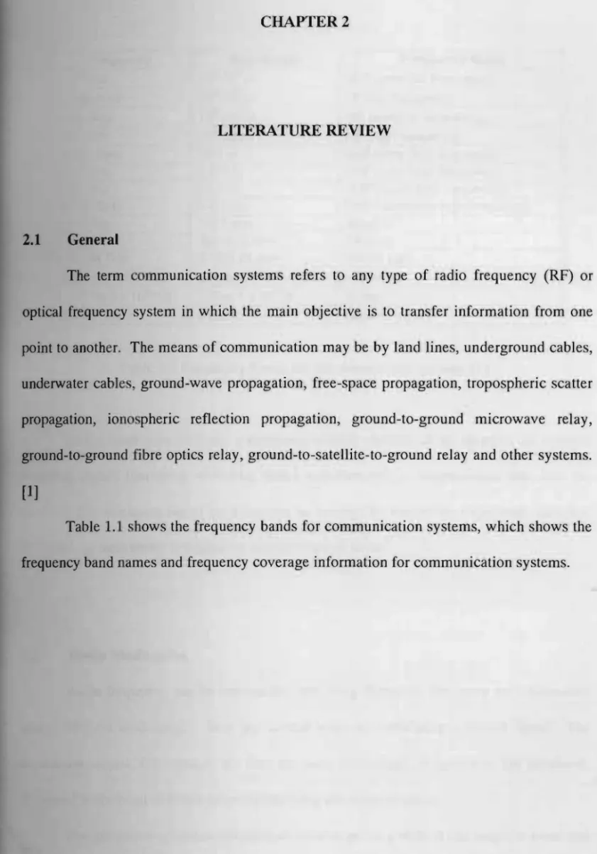
Table 1.1 shows the frequency bands for communication systems, which shows the frequency band names and frequency coverage information for communication systems.
4
Frequency Wavelength Frequency Band 3-30 KHz 105-104 m VLF (very low frequency) 30-300 KHz 104-103 m LF (low frequency) 0.3-3 MHz 103-102 m MF (medium frequency)
3-30 MHz 102-10 m HF (high frequency)
30-300 MHz 10-1 m VHF (very high frequency)
0.3-3 GHz 1-0.1 m UHF (ultra high frequency)
3-30 GHz 10-1 m SHF (super high frequency)
30-300 GHz 1-0.1 cm EHF (extremely high frequency)
0.3-3 THz 1-0.1 mm Band 12
1-417 THz 300-0.72 mm Infrared
417-789 THz 0.72-0.38 mm Visible light 789 to 5 x 10⁶ THz 0.38 to 6 x 10.5 mm Ultraviolet 3 x 10⁴ to 3 x 10srHz 100 to 1 x 10.2 A X-rays
>3 x 10⁷ THz < 0.1 A Gamma rays
Table 1.1 Frequency bands for communication systems [1]
In the mo t general case, a receiving system consists of an antenna, an antenna coupling circuit (matching networks, balun transformers), a transmission line, and the receiver. The minimum signal level that can be detected by a receiver, a spectrum analyzer, or a field strength meter is limited by the presence of noise.
2.2 Radio Modulation
Radio frequency can be transmitted over long distances, but carry no information unless they are modulated. There are several ways of modulating a carrier signal. The modulating signal, for example the data we want to transmit, is known as the baseband. Baseband is the band of frequencies representing the original signal.
The utilization of communication channel requires a shift of the range of baseband frequencies into other frequency ranges suitable for transmission, and a corresponding shift
5
back to the original frequency range after reception. This shift is accomplished by using modulation.
Modulation is defined as the process by which some characteristic of a carrier is varied in accordance with a modulating wave. Modulation is performed at the transmitting end of the communication system. After receiving a signal original baseband signal is restored by using demodulation.
Demodulation i the way to restore the original baseband signal.
2.3 Modulators and Demodulators
Modulation is the process of transferring information signals to a high-frequency carrier. A high-frequency signal has two different parameters that could be modulated (varied) in order to make it carry the information we want to transmit. They are amplitude modulation (AM) and frequency modulation (FM). If the modulator causes the amplitude of the carrier wave to vary in accordance with the modulating signal, it is called an AM modulator. If the modulator causes the frequency of the carrier wave to vary, it is an FM modulator. In the next section, each of this modulation technique will be described.
The modulator receives two inputs: the modulating signal and the carrier wave or pulse train to be modulated. The modulator then delivers an output that consists of the carrier, varying according to some characteristic of the modulating signal. The modulated signal is a composite signal that contains not only the frequency of the carrier and the modulating signal, but at 0 their sum and difference frequencies as well.
6
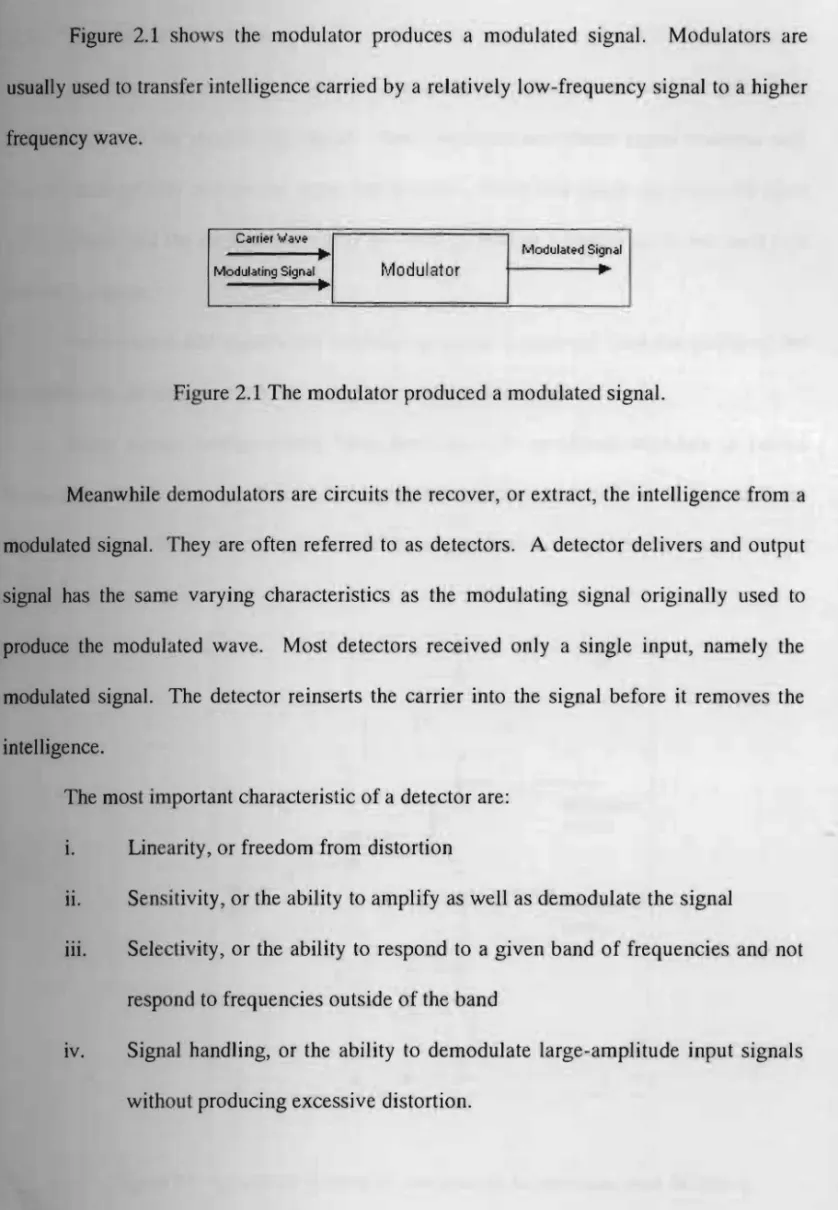
Figure 2.1 shows the modulator produces a modulated signal. Modulators are usually used to transfer intelligence carried by a relatively low-frequency signal to a higher frequency wave.
emit'r Iiiave
Modulated Signal
~
Modulating Signal Modulator
~
I
Figure 2.1 The modulator produced a modulated signal.
Meanwhile demodulators are circuits the recover, or extract, the intelligence from a modulated signal. They are often referred to as detectors. A detector delivers and output signal has the same varying characteristics as the modulating signal originally used to produce the modulated wave. Most detectors received only a single input, namely the modulated signal. The detector reinserts the carrier into the signal before it removes the intelligence.
The most important characteristic of a detector are:
i. Linearity, or freedom from distortion
11. Sen itivity, or the ability to amplify as well as demodulate the signal
iii. Selectivity, or the ability to respond to a given band of frequencies and not respond to frequencies outside of the band
IV. Signal handling, or the ability to demodulate large-amplitude input signals without producing excessive distortion.
7
.1 Amplitude Modulation (AM)
Amplitude modulator vary the amplitude, or strength, of an r-f carner In ccordance with the modulating signal. And amplitude-modulated signal contains side bands which actually contain the signal intelligence. These side bands are produced when
the r-f carrier and the modulating signal are both applied to a nonlinear device such as a tube or transistor.
For standard AM ignals, the modulating signal is removed from the output of the modulator by filtering, and only the r-f carrier and the side bands are used.
Many circuit configurations have been used to amplitude-modulate a carrier frequency. Simple circuit in Figure 2.1 shows the modulation of the latter will produce an AM output, since the current gain of a transistor depends on the collector current.
· v
[ 1
I l .~•
o--{]
f'\
) >
l---~
. .
j
c= 1
- ~
0Figure 2.2 LC circuit Q must be low enough to give band pass including modulation sidebands. [2]
8
The linearity of a modulator will be improved by the use of feedback. If the AM output is detected in a low-distortion detector, its envelope may be compared with the
riginal modulating signal.
2.3.2 Frequency Modulation (FM)
Frequency modulators vary the instantaneous frequency of an r-f carner III
accordance with the amplitude of a modulating signal. Essentially, an FM modulator con ists of a stage or device whose reactance is varied by the modulating signal; this change in reactance is then used to vary the frequency of oscillation of the oscillator that generates the r-f carrier. Unlike amplitude modulation, which is accomplished after the r-f carrier has been amplified, sometimes to a very high level, frequency modulation is carried
out at a low power level. All amplification of the output signal takes place after modulation.
FM modulation produces side-band frequencies above and below the center frequency. These side-band frequencies contain the transmitted intelligence, and with, the
oter frequency, make up the overall output signal.
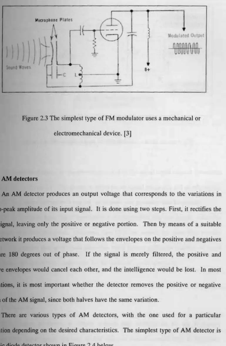
The simplest type of FM modulator uses a mechanical or electromechanical device to vary the frequency of the r-f carrier oscillator. A capacitance-type microphone can be used to control the frequ ncy at which the r-f carrier oscillator operates. It is as shown in Figure 2.3 below. It uses a capacitance-type microphone to produce audio FM modulation.
9
b
..
B+
..
Figure 2.3 The simplest type of FM modulator uses a mechanical or electromechanical device. [3]
2.4 AM detectors
An AM detector produces an output voltage that corresponds to the variations in peak-to-peak amplitude of its input signal. It is done using two steps. First, it rectifies the input signal, leaving only the positive or negative portion. Then by means of a suitable
filter network it produce a voltage that follows the envelopes on the positive and negatives are 180 degrees out of phase. If the signal is merely filtered, the positive and negative envelopes would cancel each other, and the intelligence would be lost. In most
applications, it is most important whether the detector removes the positive or negative portion of the AM signal, since both halves have the same variation.
There are various types of AM detectors, with the one used for a particular pplication depending on the desired characteristics. The simplest type of AM detector is
ic diode detector shown in Figure 2.4 below.
10

![Table 1.1 Frequency bands for communication systems [1]](https://thumb-ap.123doks.com/thumbv2/azpdforg/11277298.0/19.892.32.862.33.1241/table-1-1-frequency-bands-communication-systems-1.webp)