Wireless Power Transfer with Class E Power Amplifier and Magnetic Field Repeater
By
Ong Kim Keat 15057
Dissertation submitted in partial fulfilment of the requirements for the
Bachelor of Engineering (Hons) Electrical and Electronic Engineering
January 2015
Universiti Teknologi PETRONAS Bandar Seri Iskandar
31750 Tronoh
Perak Darul Ridzuan
i
CERTIFICATION OF APPROVAL
Wireless Power Transfer with Class E Power Amplifier and Magnetic Field Repeater
By Ong Kim Keat
15057
A project dissertation submitted to the Electrical and Electronics Engineering Programme
Universiti Teknologi PETRONAS in partial fulfilment of the requirements for the
BACHELOR OF ENGINEERING (Hons)
(ELECTRICAL AND ELECTRONIC ENGINEERING)
Approved by,
______________
(Associate Professor Ir. Dr. Perumal Nallagownden )
UNIVERSITI TEKNOLOGI PETRONAS TRONOH, PERAK
January 2015
ii
CERTIFICATION OF ORIGINALITY
This is to certify that I am responsible for the work submitted in this project, that the original work is my own except as specified in the references and acknowledgements, and that the original work contained herein have not been undertaken or done by unspecified sources or persons.
_______________________________
ONG KIM KEAT
iii
CERTIFICATION OF PAPER ACCEPTANCE FOR CEET
CONFERENCE 2015
iv
ABSTRACT
Wireless Power Transfer is the future alternative to replace overhead and underground transmission methods in delivering electrical power. The attention given to this technology has been increasing tremendously after MIT introduced Magnetic Resonance Coupling which utilizes magnetic resonance to deliver power wirelessly. There is great potential to research on this area as it can deliver power to unreachable areas and it will be the method of transmitting electrical power in the future. In this project, a combination of Class E power amplifier and magnetic field repeater is proposed with the aim of enhancing the transmission power and distance.
Besides that, Litz wire is used as the material for transmitter and receiver coil in order to reduce the skin effect because the ac resistance will increase drastically when the system is operating in high frequency. The operating frequency of the system is chosen to be at 250 kHz in simulation stage. This paper compares the performance of the system with and without magnetic field repeater. 0.41mW is obtained at 40cm from the transmitter without repeater and 511.20mW at 40cm with repeater.
v
ACKNOWLEDGEMENT
The author would like to express his deepest gratitude and appreciation to everyone who has assisted him throughout his Final Year Project.
First and foremost, the author is very thankful to Assoc. Prof. Ir. Dr. Perumal who is his Final Year Project supervisor for his guidance and willingness to provide insight when needed. The knowledge, insight and experience that he shared are very significant in becoming a successful engineer.
Besides that, the author would like to acknowledge with a deep sense of gratitude towards his parents and family members who always give him their full support throughout this project.
Lastly, the author would like to thank Universiti Teknologi PETRONAS Communication Lab for their technical support to accomplish this project.
vi
TABLE OF CONTENT
CERTIFICATION OF APPROVAL ... i
CERTIFICATION OF ORIGINALITY ...ii
CERTIFICATION OF PAPER ACCEPTANCE FOR CEET CONFERENCE 2015 ... iii
ABSTRACT ... iv
TABLE OF CONTENT ... vi
LIST OF FIGURES ... viii
LIST OF TABLES ... ix
CHAPTER 1 ... 1
INTORDUCTION ... 1
1.1 Background of Study ... 1
1.2 Problem Statement ... 3
1.3 Objectives ... 4
1.4 Scope of Study ... 4
CHAPTER 2 ... 5
LITERATURE REVIEW ... 5
2.1 Resonant Frequency ... 5
2.2 Techniques for WPT ... 6
2.2 Class E Power Amplifier... 7
2.3 Magnetic Field Repeater ... 9
2.4 Material of the coil used in Transmitter and Receiver ... 10
CHAPTER 3 ... 11
METHODOLOGY ... 11
3.1 Research Methodology ... 11
3.2 Design Characteristic of the WPT Circuit ... 12
3.3 Tools Required ... 13
3.4 Design Class E Power Amplifier ... 14
3.41 Selection of MOSFET ... 16
3.5 Magnetic Field Repeater ... 16
3.6 Gantt Chart for FYP1 ... 17
3.7Gantt Chart for FYP2 ... 18
CHAPTER 4 ... 19
vii
RESULT AND DISCUSSION ... 19
4.1 Class E Power Amplifier Simulation ... 19
4.2 Inductance of the Litz Wire Coil ... 22
4.3 Frequency Source ... 22
4.4 Laboratory Wireless Power Transfer Result ... 23
4.5 Wireless Power Transfer Prototype Result ... 28
CHAPTER 5 ... 32
CONCLUSION AND RECOMMENDATION ... 32
5.1 Conclusion ... 32
5.2 Recommendation ... 33
REFERENCES ... 34
viii
LIST OF FIGURES
Figure 1: Wardenclyffe Tower ... 1
Figure 2: Experiment about Natural Frequency... 5
Figure 3: Microwave Power Transmission ... 6
Figure 4: SCMR Introduced by MIT ... 7
Figure 5: Class E Power Amplifier Circuit ... 8
Figure 6: Magnetic Field Repeater ... 9
Figure 7: Skin Effect on Conductor at High Frequency ... 10
Figure 8: Litz Wire ... 10
Figure 9: Block Diagram of the WPT System ... 12
Figure 10: Normal Switching ... 14
Figure 11: Zero Voltage Switching ... 14
Figure 12: Magnetic Field Repeater Configuration ... 16
Figure 13: Gantt chart FYP1 ... 17
Figure 14: Gantt Chart FYP2 ... 18
Figure 15: Schematic of Class E Power Amplifier ... 19
Figure 16: Zero Voltage Switching across the MOSFET ... 20
Figure 17:Resonant Frequency of the LC Series Circuit ... 21
Figure 18: Inductance Measure using Agilent Handheld RLC ... 22
Figure 19: Experimental Setup of WPT ... 23
Figure 20: ZVS across MOSFET ... 23
Figure 21: Power (mW) against Distance (cm) with and without repeater ... 27
Figure 22: Wireless Power Transfer Prototype ... 28
Figure 23: Transmitter ... 29
Figure 24: Magnetic Field Repeater ... 29
Figure 25: Receiver... 30
Figure 26: Output Waveform Received ... 30
ix
LIST OF TABLES
Table 1: IRF 530 Characteristic ... 16
Table 2: Result without Repeater ... 25
Table 3: Result with Repeater ... 26
Table 4: Comparison with Previous Result ... 31
Table 5: Technical Specification of WPT Prototype ... 31
1
CHAPTER 1
INTORDUCTION
1.1 Background of Study
Wireless Power Transfer (WPT) is to transmit electrical power to an electrical load without connecting wires. This method is extremely useful in powering up devices at unreachable location such as underwater machine and biomedical implant. This technology has existed for over a century, Nikola Tesla was the pioneer that proposed to transmit the electrical power wirelessly. In 1901, the Wardenclyffe Tower was designed by Nikola Tesla to demonstrate the concept of Wireless Power Transfer [1], however due to financial constraint this project was unable to carry out.
Recently, due to the increase demand of charging portable electronic appliances, electric cars and medical devices that are embedded in human body has caused the WPT to gain back the attention. By having WPT, all the devices can be powered up automatically and wirelessly once it is within range of power transfer. This is definitely bringing more conveniences to human being.
Figure 1: Wardenclyffe Tower
2
In 2007, there is a ground breaking success of WPT by the researchers from Massachusetts Institute of Technology (MIT) [2]. They are the first one who proposed the Strongly Coupled Magnetic Resonance (SCMR) technique to perform WPT. They have successfully lighted up a 60W light bulb with the distance of 2m between the transmitter and receiver. With their huge success, they have established a company named “Witricity” which commercializes their products in the market.
There is a drastically increase in the number of research done on WPT after MIT in order to find out a way to increase the power efficiency and transmission distance.
Several methods such as power amplifier, resonance frequency, resonance repeater and type of core used were introduced to incorporate with the (SCMR) to increase the power efficiency and transmission distance [3-8].
The disadvantage of magnetic charging is that it is inefficient when the distance between two coils. This downside can be compensated by using SCMR which utilizes both resonance frequency and magnetic induction to perform wireless power transfer. In addition, the method used by SCMR is non-radiation power which will not bring any harm to human being.
3 1.2 Problem Statement
Recently, there are groups of environmentalists against the construction of overhead line in European country. They claimed that negative impacts of the overhead line outweigh its advantages. Besides that, the construction of underground cables is unfavorable because it involves digging in the city. Due to the increase in energy demand, the utility has no choice but to deliver higher power on the transmission line.
This has caused frequent tripping to occur as it exceeds the limit of the transmitting cable.
WPT has a wide range of possibility in term of application in future. This technology can gradually become the main power transmission method in the near future to replace overhead lines and underground cables.
The second problem statement is the high power consumption of electronic device.
These devices require regular charging as the battery depletes very fast has to be charged by plugging into a wall outlet which brings a lot of inconvenience.
Besides that, this system is useful in powering up the devices in the unreachable areas such as underwater machines and biomedical implant devices. For instance, the pacemakers don’t have to be surgically replenished with batteries every few year and can be charged wirelessly. However, the major issues on the WPT are the transmission distance still remains in the mid-range and low efficiency level. This has caused it not yet feasible for long distance transmission. Further research has to be done to enhance and optimize the WPT.
4 1.3 Objectives
The objectives of the project are
1. to understand the concept of WPT
2. to design and build a system with magnetic field repeater to enhance power transmission and distance
1.4 Scope of Study
The scope of study for the project covers the following:
1. To study the operating principle of power amplifier 2. To study various methods of WPT
3. To analyse the effect of magnetic field repeater on WPT system
5
CHAPTER 2
LITERATURE REVIEW
2.1 Resonant Frequency
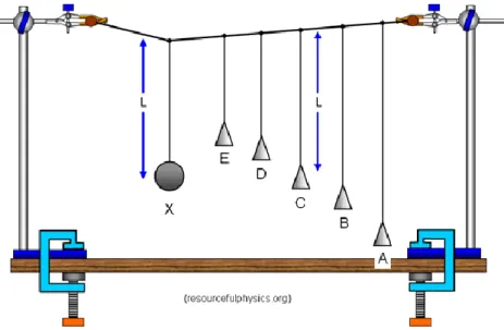
When the object is oscillating at its natural frequency, it will achieve its greatest amplitude. For instance, Barton’s pendulums can be used to illustrate the effect of forced vibration and resonance. When the driving pendulum starts vibrating at its natural frequency, the pendulum which has the same natural frequency will tend to vibrate more vigorously compared to others.
Figure 2: Experiment about Natural Frequency
6 2.2 Techniques for WPT
There are three most well-known methods can be used to perform WPT. The first method is by using inductive coupling technique [9, 10]. Its operating principle is based on Faraday’s Law which states that an electromotive force (emf) will be induced in a coil when there is rate of change of magnetic field. Nevertheless, the low efficiency for long distance has caused this method to have limited prospect to be used for long distance power transmission.
The second method is to use microwave power transmission[11]. This method is able to transmit the power up to few kilometres however, sophisticated equipment is needed to track and capture the power transfer. This has caused this technique not feasible in long term power transmission.
Figure 3: Microwave Power Transmission
SCMR that was introduced by MIT researchers has compensated the weakness of these two methods in 2007. The operating principle is similar to the inductive coupling but with an enhancement of resonance operating frequency[2]. By implementing the resonance in WPT, little excitation is needed for the system to develop a huge stored energy as object with the same resonance frequency can exchange energy efficiently. Basically, an electromagnetic resonator is built up from three simplest and most common electrical components which are resistor, inductor and capacitor. The resonant frequency can be expressed as[4]
𝜔0 = 1
√𝐿𝐶
7 while the Q-factor can be expressed as
𝑄 =𝜔0𝐿 𝑅
Q-factor is the essential element in determining the efficiency of WPT [12, 13].
By having low resistance value and high resonant frequency and inductance in the circuit will help the system to enhance its performance. When the system is operating at its resonant frequency, the inductive and capacitive elements will perform LC cancellation and cause the circuit to behave like a resistive circuit[13].
Figure 4: SCMR Introduced by MIT
2.2 Class E Power Amplifier
There are two classes of power amplifier suitable to be used for WPT. Based on the research done by [6, 7], Class E is better than Class D in this application because it requires lesser components but produces promising result. The drawback of this power amplifier is that it has to go through long iteration to complete the circuit design phase. However, a simplified mathematic equation was proposed by [14] is able to get a reasonably approximated result. The implementation on zero voltage switching has lessened the power losses in power amplifier and thus successfully increased the system efficiency to more than 80%. The following are the equations to design Class E power amplifier[14].
8 𝐾𝐿(𝑞) =𝜔𝐿
𝑅 𝐾𝐶(𝑞) = 𝜔𝐶𝑅 𝐾𝑃(𝑞) =𝑃𝑂𝑈𝑇𝑅
𝑉𝐷𝐷2 𝐾𝑋 =𝑋
𝑅 Equation for (0.6< q < 1)
𝐾𝐿(𝑞) = 44.93𝑞2− 94.32𝑞 + 52.46 𝐾𝐶(𝑞) = 0.426𝑞2− 0.379𝑞 + 0.3 𝐾𝑃(𝑞) = 0.74𝑞2− 0.6𝑞 + 0.76 𝐾𝑋(𝑞) = −0.73𝑞2+ 0.411𝑞 + 1.03 Equation for (1< q < 1.65)
𝐾𝐿(𝑞) = 8.085𝑞2− 24.53q + 19.23
𝐾𝐶(𝑞) = −6.97𝑞3+ 25.93𝑞2− 31.071𝑞 + 12.48 𝐾𝑃(𝑞) = −11.90𝑞3 + 42.753𝑞2− 49.63𝑞 + 19.70 𝐾𝑋(𝑞) = −2.9𝑞3+ 8.8𝑞2− 10.2𝑞 + 5.02
Figure 5: Class E Power Amplifier Circuit
9 2.3 Magnetic Field Repeater
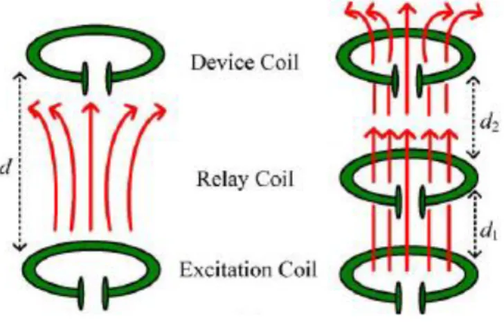
In WPT system, the higher the magnetic field received by receiver, the higher the efficiency. However, the long separation distance between transmitter and receiver causes the low magnetic coupling effect which results short transmission distance of WPT system. This is because insufficient magnetic field is captured by receiver which causes it unable to power up the load. One of the alternatives to overcome this issue is by inserting a relay resonator in between the transmitter and receiver [8, 15, 16]. The relay resonator can enhance the magnetic coupling by concentrating and relaying the magnetic flux to a longer distance. In [8], it shows that for the odd number of repeater, the system achieve its optimum performance at the original resonant frequency but it does not apply on even number of repeaters. Total number of repeaters has to be carefully selected to avoid frequency splitting effect which will reduce the overall transmission efficiency.
Figure 6: Magnetic Field Repeater
10
2.4 Material of the coil used in Transmitter and Receiver
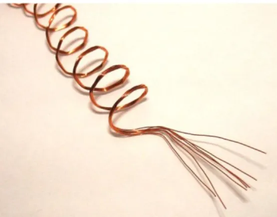
The Litz wire or magnetic wire which is made out of many individually insulated copper wires that are stranded together is suitable to be used as the primary and secondary winding to minimize the resistance and skin effect in the system[3, 5].
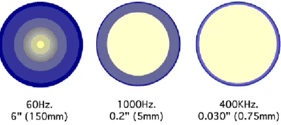
When the system is operating at the high frequency, the current tends to flow at the surface of the conductor which causes the AC resistance to increase significantly. The figure below shows the current penetration depth on conductor when the current is flowing at the high frequency (current is shown in blue colour). By decreasing the total resistance in the circuit, the Q-factor is increased which will contribute to greater performance.
Figure 7: Skin Effect on Conductor at High Frequency
Figure 8: Litz Wire
11
CHAPTER 3
METHODOLOGY
3.1 Research Methodology
There are three phases that will be gone through which is designing phase, simulation phase and constructing phase. The designing phase is about selecting the resonant frequency, the input voltage and current, types of capacitor etc. for the project. Once the first phase is completed, simulation will be done by using LT Spice to prove that the combination can achieve the desired result. Lastly, all the components will be finalized and purchased to construct the real prototype.
Design Simulation Prototype
12
3.2 Design Characteristic of the WPT Circuit
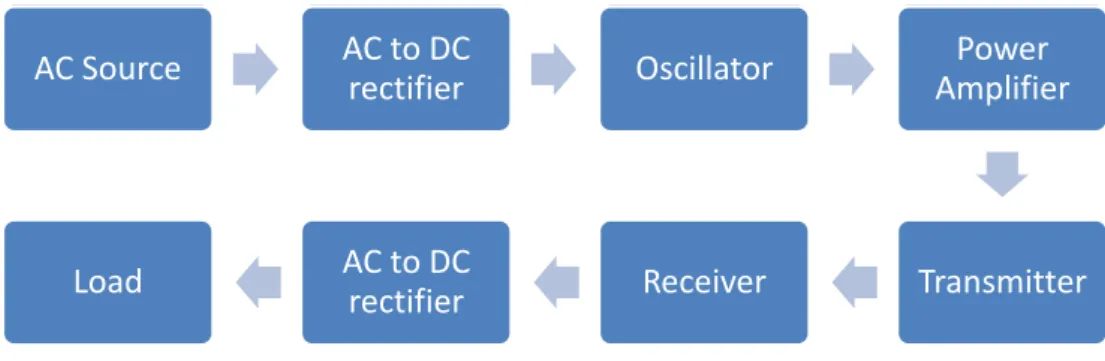
Figure 9: Block Diagram of the WPT System
The block diagram shows the essential elements in the WPT system. In this section, design criteria for each element will be discussed and analyzed.
A 5V DC power adapter will be used to power the circuit with the current of 1.5A. High current is needed to have better transmission distance and efficiency.
The current is limited to 1.5A due to the maximum current that the litz wire can withstand is around 2A.
Frequency generator will be used as the source of oscillator that provides 50%
duty cycle square waveform to the gate of the N-MOS transistor. The frequency used for simulation is set as 250 kHz. The frequency is subjected to be changed when constructing the real circuit as the inductance of the transmitter coil is not yet determined. The range of frequency should be selected at the medium range in order to compare the current project result with the previous project.
Class E power amplifier is the best candidate to be used for inductive load due to its efficiency and lesser components needed. The transmitter and receiver will be built by using Litz wire to reduce the skin effect. A magnetic field repeater will be inserted in between the transmitter and receiver to enhance the overall performance. The load will be a LED or light bulb depends on the power captured by receiver.
AC Source AC to DC
rectifier Oscillator Power
Amplifier
Transmitter Receiver
AC to DC rectifier Load
13 3.3 Tools Required
a. Software
No. Software Explanations
1 Microsoft Office Excel Use to plot graph 2 Microsoft Office Word Use to prepare report 3 Microsoft Office PowerPoint Use to prepare presentation slides
4 LT Spice Use for project simulation
b. Hardware
No. Hardware Explanations
1 GW Instek Laboratory DC Power Supply
Use for DC power supply 2 Tektronic TDS 1002 Digital
Oscilloscope
Use to measure the voltage waveform 3 Agilent 33500B Series
Waveform Generator
Use to create impulse to activate the Mosfet
4 Agilent Handheld RLC meter Use to measure coil inductance 5 Multimeter Use to measure voltage and current
14 3.4 Design Class E Power Amplifier
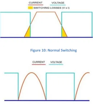
Zero Voltage Switching (ZVS) behaviour of Class E power amplifier has caused it to have lower power dissipation compared to other power amplifier. The diagram below shows the differences between normal switching and ZVS. By turn on and off the MOSFET at zero voltage, there is no interception area between voltage and current. The overlapping area of voltage and current will contribute to power losses in the system. The operating frequency which is 250 kHz will be used as the resonance frequency of the system when determining the components values.
Figure 11: Zero Voltage Switching Figure 10: Normal Switching
15
Using the formulae discussed in the section 2.2 and by selecting 𝑞 = 1.412, the coefficients of the each element in the equations will be
𝐾𝐿 0.713
𝐾𝐶 0.685
𝐾𝑃 1.36
𝐾𝑋 -0.00143
The parameters of 𝑉𝐷𝐷 = 5𝑉, 𝑞 = 1.412, 𝑅 = 22Ω, 𝜔 = 2𝜋(250𝑘), 𝑓 = 250𝑘𝐻𝑧 are set.
𝐾𝐿 =𝜔𝐿1 𝑅
0.713 =(2𝜋(250𝑘))(𝐿1) 22
𝑳𝟏= 𝟏𝟎𝝁𝑯 𝐾𝐶 = 𝜔𝐶1𝑅
0.685 = (2𝜋(250𝑘))(𝐶1)(22) 𝑪𝟏 = 𝟏𝟗. 𝟖𝒏𝑭
𝐾𝑃 = 𝑃𝑂𝑈𝑇𝑅 𝑉𝐷𝐷2 1.36 =𝑃𝑂𝑈𝑇(22)
52 𝑷𝑶𝑼𝑻 = 𝟏. 𝟓𝟒𝑾 𝐾𝑋 =𝑋
𝑅
−0.00143 = 𝑥 22 𝑥 = −0.03146 = 1
𝑗𝜔𝐶 𝒙 = 𝟐𝟎𝝁𝑭
𝜔 = 1
√𝐶𝑜𝐿𝑜 𝑙𝑒𝑡 𝐿𝑜= 68𝑢𝐻 𝑪𝒐 = 𝟓. 𝟔𝒏𝑭
16 3.41 Selection of MOSFET
The function of the MOSFET is act as a switching device to turn on and off the circuit at desired time. The current will pass through when the MOSFET is turned on, and the voltage will be at its maximum when the MOSFET is turned off. In order to obtain better result, there are few criteria that must be fulfilled in MOSFET selection. The low parasitic capacitance and internal resistance of MOSFET is more favourable to be used in Class E Power Amplifier. After comparing few models of MOSFET, IRF 530 is selected to be used due to its low parasitic capacitance characteristic.
Table 1: IRF 530 Characteristic
3.5 Magnetic Field Repeater
The total number of magnetic field repeater that will be built in this project is odd number due to the reason that it can achieve its optimum condition with the original resonant frequency. It will ease the construction process by using the same resonant frequency as the base to construct 𝜔0 = 1
√𝐿𝑇𝑋𝐶1 = 1
√𝐿𝑅𝑋𝐶2 =
1
√𝐿𝑅𝐸𝑃𝐶3 .
Figure 12: Magnetic Field Repeater Configuration
17 3.6 Gantt Chart for FYP1
Figure 13: Gantt chart FYP1
18 3.7Gantt Chart for FYP2
Figure 14: Gantt Chart FYP2
19
CHAPTER 4
RESULT AND DISCUSSION
4.1 Class E Power Amplifier Simulation
The circuit is built on the LT Spice based on the calculation that is shown in methodology to simulate and prove that it is working before constructing the real circuit.
Figure 15: Schematic of Class E Power Amplifier
A 555 timer is used to produce 250 kHz oscillating frequency with 50% duty cycle and square waveform. The MOSFET IRF530 is used in the simulation as it has lower parasitic capacitance which can contribute a better performance on ZVS. The drain of the MOSFET is connected with 5V DC. The 68𝜇𝐻 of the inductor will be replaced by the transmitter coil in the real prototype. In this simulation, two things are observed which are ZVS of the class E power amplifier is reached and a sine waveform is produced across the inductor.
20
Figure 16: Zero Voltage Switching across the MOSFET
The diagram above shows that the ZVS is achieved in the class E power amplifier.
The MOSFET is switched on during off time of the square waveform and vice versa.
However, there is a small ripple appears at the zero voltage. It is expected that it might cause some disturbances on the real prototype.
ZVS is achieved
21
Figure 17:Resonant Frequency of the LC Series Circuit
It is observed that the time taken for one cycle of oscillation of the LC series circuit is about 4.3us which is about 230k Hz which is slightly lower than the operating frequency. With this, all the criteria of Class E power amplifier have been verified and ready to be constructed.
22 4.2 Inductance of the Litz Wire Coil
Figure 18: Inductance Measure using Agilent Handheld RLC
The winding of the coil was done manually due to the unavailability of the winding machine. The number of the turns per coil is 16 and the inductance measured is around 57 uH. The difference between the value of inductance during simulation (250 kHz) and real prototype has caused the resonant frequency of the prototype (290 kHz) higher. The measurement was done by using Agilent U1733C Handheld LCR Meter. The same number of turns is applied on the transmitter, repeater and receiver in order to achieve the same inductance value.
4.3 Frequency Source
The initial planning was to use the 555 timer circuit as the source to generate pulse for the MOSFET gate. However, it is realized that the timer circuit couldn’t generate pure pulse waveform which will deteriorate the performance of the system. The frequency source is then changed to Agilent Frequency Generator.
23
4.4 Laboratory Wireless Power Transfer Result
Figure 19: Experimental Setup of WPT
The circuit is built based on the calculation done in the methodology part. All the values used in the simulation stage will be used in building up the circuit except the inductance value has changed from 68 uH to 58uH. Besides that, the L2 of the circuit is then replaced with the Litz wire coil in order to transmitter power wirelessly. The capacitor value of 5.6nF is used on these three circuits to achieve same resonance frequency. The setup of the circuit is shown is Figure 5.
Figure 20: ZVS across MOSFET
24 𝑓𝑅 = 1
2𝜋√𝐿𝐶
= 1
2𝜋(58𝜇)(5.6𝑛)
= 279𝑘𝐻𝑧
The theoretical resonant frequency is 280 kHz. However, the circuit is then running with frequency started from 100 kHz and it is increased by 10 kHz and the waveform is recorded down by using the Anritsu MS2034B Network Analyser. It is then observed that the waveform reached its peak at 290 kHz. The maximum transfer of energy happens at the resonant frequency which confirms that 290 kHz is the resonant frequency of the system.
Once the resonant frequency is confirmed, 290 kHz of square wave is then supplied by using Agilent Waveform Generator 33500B series to the gate of the IRF530 in order to switch on the MOSFET. Figure 6 shows that the circuit built has achieved zero voltage switching which means that the Class E power amplifier is successfully designed. The ZVS helps to reduce the power loss in transmitter circuit.
25
Table 2: Result without Repeater Without Repeater
Distance cm) Voltage (V) Current (mA) Power (mW)
0 0 0 0
5 46.1 13.4 617.74
10 213 17.7 3770.10
15 152 16.3 2477.60
20 41 10.9 446.90
25 22 2.5 55.00
30 13.7 1.39 19.04
35 10.5 0.68 7.14
40 6.79 0.06 0.41
45 4.64 0.04 0.19
50 3.45 0.007 0.02
26
Table 3: Result with
Repeater
With Repeater
Distance cm) Voltage (V) Current (mA) Power (mW)
0 0 0 0
5 0 0 0
10 45.20 16.70 754.84
15 74.00 18.90 1398.60
20 103.00 18.70 1926.10
25 219.00 16.40 3591.60
30 157.00 15.90 2496.30
35 94.80 14.20 1346.16
40 56.80 9.00 511.20
45 39.80 1.71 68.06
50 25.90 1.50 38.85
55 19.80 0.90 17.82
60 14.40 0.48 6.91
65 12.40 0.17 2.11
70 9.67 0.05 0.44
Table 3: Result with Repeater
27
Figure 21: Power (mW) against Distance (cm) with and without repeater 0.00
250.00 500.00 750.00 1000.00 1250.00 1500.00 1750.00 2000.00 2250.00 2500.00 2750.00 3000.00 3250.00 3500.00 3750.00 4000.00
0 10 20 30 40 50 60 70 80
Power (mW) against Distance (cm)
without repeater with repeater
28
Referring to the Table 1 and 2, it shows that the circuit without magnetic field repeater can transfer significant power at the maximum distance of 35 cm whereas the circuit with the magnetic field repeater it can enhance the performance to 65 cm.
By comparing the result, it shows that the magnetic field repeater can help to deliver more power. The maximum power obtained with magnetic field repeater is 3.59 W at 25 cm and it decreases until 65 cm. This project has improved the previous project by 8.85 times in terms of power transmitted and the distance is increased by 35 cm.
4.5 Wireless Power Transfer Prototype Result
Figure 22: Wireless Power Transfer Prototype
Once the circuit is confirmed by the experiment on the breadboard, the circuit is then constructed by using Printed Circuit Board (PCB) in order to minimize the noise of the circuit. Furthermore, the coil housings and coil bases are the constructed by using the 3D printing. The figure above shows that the maximum distance that a LED can be lighted up is at 100cm away from the transmitter.
29
Figure 23: Transmitter
There are three wires which are in white, orange and blue colors. To start up the circuit, the blue wire has to be connected with DC power supply with the voltage of 5V and current of 1.5 A. The orange wire has to be connected by the waveform generator which generates a 290 kHz square wave with 5 Vrms. The grounds of the DC power supply and waveform generator need to be connected at the white wire.
Figure 24: Magnetic Field Repeater
The magnetic field repeater is placed between the transmitter and receiver in order to enhance the performance of the system. It is found out that the optimum result can be obtained if the repeater is placed at 10 cm away from the receiver. The repeater is
30
used to enhance the coupling of the magnetic field so that the receiver can obtained more power.
Figure 25: Receiver
The Led is used as an indicator of the power transmission. The Led can be replaced with rectifier circuit to convert AC to DC for various applications.
Figure 26: Output Waveform Received
A smooth sinusoidal waveform is received at the receiver. The Vrms with the value of 28.78 V is obtained at the receiver.
31
Description Distance (cm) Power (mW)
Maximum Distance for Previous Project 30 3.068
Maximum Power Received for Previous Project 10 418.42
Maximum Distance for This Project 65 2.11
Maximum Power Received for This Project 25 3591.60
Table 4: Comparison with Previous Result
By comparing to the previous project, there is a great improvement in term of performance of the circuit. For instance, the maximum power transferred for previous project was 418.42 mW whereas this project has successfully received 3591.6 mW at 25 cm. In addition, this project has improved the previous project by 8.58 times in terms of power transmitted and the distance is increased by 35 cm.
Technical Specification
Power Supply Voltage (V) 5
Current (A) 1.5
Operating Frequency (kHz) 290
Output Power Distance (cm) 25
Power (mW) 3591.6
Coil Dimension
Wire Diameter (cm) 0.01 Coil Diameter (cm) 11.5 Width of Coil (cm) 1.5
Number of turns 15
Number of layers 2
Table 5: Technical Specification of WPT Prototype
32
CHAPTER 5
CONCLUSION AND RECOMMENDATION
5.1 Conclusion
In a nutshell, the objectives of this project are achieved. This project has successfully improved the power transmission and distance by the combination of Class E power amplifier and magnetic field repeater. The Zero Voltage Switching of Class E power amplifier helps to reduce power dissipation which allows more power to be transfer.
Besides that, the magnetic field repeater acts as a relay resonator which allows the wireless power to transmit at a greater distance with significant power. Lastly, the Litz wire has overcome the skin effect when the system is operating at high frequency.
The maximum power receiver with magnetic field repeater is 3.59W which has increased 8.58 times compared to the previous project. Besides, the maximum distance to deliver significant power has improved to 65 cm which is 35 cm longer than the previous project. From the results obtained, it proves that it can enhance the performance of the WPT system.
This project consists of comprehensive studies related to wireless power transfer with the experiment work done as well as the prototype demonstration. it has established a strong foundation for people to continue improving it to make it more feasible for wider range of application.
33 5.2 Recommendation
There are few ways can be adapted into this design in order achieve greater result.
Firstly, the improvement can be done by having a ferrite material as a core to enhance the coupling effect of the magnetic field. The ferrite material has been used in transformer in order to reduce the flux leakage. The ability to capture the magnetic field is vital to obtain the maximum power transfer. In addition, the shape of the coil can be changed to spiral in order to allow the magnetic field to transmit at a greater surface area.
34
REFERENCES
[1] J.-W. Li, "Wireless power transmission: State-of-the-arts in technologies and potential applications," in Microwave Conference Proceedings (APMC), 2011 Asia-Pacific, 2011, pp. 86-89.
[2] A. Kurs, A. Karalis, R. Moffatt, J. D. Joannopoulos, P. Fisher, and M.
Soljačić, "Wireless power transfer via strongly coupled magnetic resonances," science, vol. 317, pp. 83-86, 2007.
[3] C. Park, S. Lee, G. H. Cho, and C. T. Rim, "Innovative 5-m-Off-Distance Inductive Power Transfer Systems With Optimally Shaped Dipole Coils,"
Power Electronics, IEEE Transactions on, vol. 30, pp. 817-827, 2015.
[4] O. Jonah and S. V. Georgakopoulos, "Optimized helix with ferrite core for wireless power transfer via resonance magnetic," in Antennas and Propagation Society International Symposium (APSURSI), 2013 IEEE, 2013, pp. 1040-1041.
[5] L. Hee-Jin, B. Jin-Young, and C. Chin-Wook, "Electromagnetically coupled resonators using toroidal ferrite core for wireless power transfer," in Microwave Workshop Series on Innovative Wireless Power Transmission:
Technologies, Systems, and Applications (IMWS), 2012 IEEE MTT-S International, 2012, pp. 183-186.
[6] W.-T. Chen, R. A. Chinga, S. Yoshida, J. Lin, and C.-K. Hsu, "A 36 W Wireless Power Transfer System with 82% Efficiency for LED Lighting Applications."
[7] W. Chen, R. A. Chinga, S. Yoshida, J. Lin, C. Chen, and W. Lo, "A 25.6 W 13.56 MHz wireless power transfer system with a 94% efficiency GaN Class- E power amplifier," in Microwave Symposium Digest (MTT), 2012 IEEE MTT-S International, 2012, pp. 1-3.
[8] A. Dukju and H. Songcheol, "A Study on Magnetic Field Repeater in Wireless Power Transfer," Industrial Electronics, IEEE Transactions on, vol.
60, pp. 360-371, 2013.
[9] L. Zhen Ning, R. A. Chinga, T. Ryan, and L. Jenshan, "Design and Test of a High-Power High-Efficiency Loosely Coupled Planar Wireless Power Transfer System," Industrial Electronics, IEEE Transactions on, vol. 56, pp.
1801-1812, 2009.
[10] J. J. Casanova, L. Zhen Ning, and L. Jenshan, "A Loosely Coupled Planar Wireless Power System for Multiple Receivers," Industrial Electronics, IEEE Transactions on, vol. 56, pp. 3060-3068, 2009.
[11] W. C. Brown, "Status of the Microwave Power Transmission Components for the Solar Power Satellite," Microwave Theory and Techniques, IEEE Transactions on, vol. 29, pp. 1319-1327, 1981.
[12] P. Jae-Hyun, P. Byung-Chul, L. Jeong-Hae, R. Young-Ho, P. Eun-Seok, and K. Sang-Wook, "Optimum frequency of high Q-factor resonator for magnetic resonance coupling," in Microwave Conference (EuMC), 2011 41st European, 2011, pp. 61-63.
[13] Y. Kawamura and M. Shoyama, "Wireless power transmission using LC cancellation," in ECCE Asia Downunder (ECCE Asia), 2013 IEEE, 2013, pp.
1041-1045.
35
[14] M. Acar, A. J. Annema, and B. Nauta, "Generalized Design Equations for Class-E Power Amplifiers with Finite DC Feed Inductance," in Microwave Conference, 2006. 36th European, 2006, pp. 1308-1311.
[15] Z. Xiu, S. L. Ho, and W. N. Fu, "Quantitative Design and Analysis of Relay Resonators in Wireless Power Transfer System," Magnetics, IEEE Transactions on, vol. 48, pp. 4026-4029, 2012.
[16] L. Chi Kwan, W. X. Zhong, and S. Y. R. Hui, "Effects of Magnetic Coupling of Nonadjacent Resonators on Wireless Power Domino-Resonator Systems,"
Power Electronics, IEEE Transactions on, vol. 27, pp. 1905-1916, 2012.