i
VARIABLE FREQUENCY DRIVE (VFD) DESIGN IMPROVEMENT TO SURVIVE DURING VOLTAGE DIP
By
Gerardo Ondo Micha Adjayeng ID 15760
Dissertation Submitted
In Partial Fulfillment of the Requirements for the Bachelor of Engineering (Hons)
(Electrical & Electronic Engineering)
JANUARY 2017
Universiti Teknologi PETRONAS Bandar Seri Iskandar
31750 Tronoh Perak Darul Ridzuan
ii
CERTIFICATION OF APPROVAL
VARIABLE FREQUENCY DRIVE (VFD) DESIGN IMPROVEMENT TO SURVIVE DURING VOLTAGE DIP
By
Gerardo Ondo Micha Adjayeng 15760
A project dissertation submitted to the Electrical and Electronic Engineering Programme
Universiti Teknologi PETRONAS in partial fulfilment of the requirement for the
Bachelor of Engineering (Hons)
(ELECTRICAL AND ELECTRONIC ENGINEERING)
Approved by,
_____________________
Ir. Dr Mohd Faris Bin Abdullah
UNIVERSITI TEKNOLOGI PETRONAS TRONOH, PERAK
January 2017.
iii
CERTIFICATION OF ORIGINALITY
This is to certify that I am responsible for the work submitted in this project, that the original work is my own except as specified in the references and acknowledgements, and that the original work contained herein have not been undertaken or done by unspecified sources or persons.
___________________________________________
Gerardo Ondo Micha Adjayeng
iv ABSTRACT
Variable Frequency Drive Design (VFD) improvement to survive during voltage dip is an open and yet interesting area of research given the importance and impact of VFD trip in modern industries. Improving the design of a VFD that will keep the DC-link bus voltage above the tripping value for the duration of the voltage dip is the very best interest of this research. In order to fulfill the requirements of this study, a design that includes a supercapacitor in the DC-link bus voltage will be proposed. The first stage is to use Simulink software to examine the behavior of the VFD during voltage dip without the proposed supercapacitor implementation. In the same sequence of events, a supercapacitor will be introduced to the design to see and examine the ride-through capability of the proposed method. It is specially challenging to figure out the way to implement the idea and to be able to run it on Simulink software. After implementing the proposed design, it is expected that when a supercapacitor is placed in the DC-link bus of the VFD, the device will be able to survive during voltage dip without tripping, for both the overload and no load conditions. Simulink software will be used to simulate an existing model of VFD for different fault and load conditions. The proposed model will also be simulated using a supercapacitor. The proposed design will not only fulfill the project requirements, it is also cheaper and even reliable and efficient than the other alternatives like using a booster, battery or a change in the algorithm. In order to achieve and improve the ride-through capability of the VFD during voltage dip, this study proposes the use of a 1.5 F and 5.4 V supercapacitor, placed in the DC-link in parallel with the actual capacitor. This results in a VFD with higher ride-through capability.
With the supercapacitor implementation, the VFD only trips for voltage dip of less than 30% and after 60 seconds.
v
ACKNOWLEDGEMENTS
Foremost, I would like to start these lines by expressing my sincerest thanks and praises to GOD ALMIGHTY for proving me with the strength and ability to carry on and successfully completing this project.
I would also like to take this opportunity to thank Noble Energy EG Ltd for awarding me the scholarship to study this engineering degree. It is an honor for me to having taken part of Noble Energy community, I will never be thankful enough.
As a world class university, UTP has been a home for me from day one. I cannot imagine a better environment to excel and perform at my best. Top facilities, lectures and most important of all, a culture of diversity. Special thanks to my project supervisor Ir Dr. Mohd Faris Bin Abdullah for guiding me through all stages of this study, I am forever grateful.
Finally, to my caring, loving and supportive parents, Fortunato Micha Ntutumu and Juventina Adjayeng Obiang: my deepest gratitude. Your encouragement when the times got rough is much appreciated and duly noted. My debt to you is immeasurable, you made all this possible with your unyielding support and this degree goes to you. Thank you very much.
vi
TABLE OF CONTENTS
Page
CERTIFICATION OF APPROVAL……….…..…..ii
CERTIFICATION OF ORIGINALITY………...iii
ABSTRACT………..………...iv
ACKNOWLEDGEMENTS………...……….….…v
LIST OF FIGURES………..…………..……..viii
LIST OF TABLES………..…………ix
LIST OF ABBREVIATIONS………..x
CHAPTER1: INTRODUCTION…………..……….……..…...1
1.1 Background of Study……….……...….…...…..1
1.2 Problem Statement………..…..……….…...1
1.3 Objectives ….……….…2
1.4 Scope of Study………...2
CHAPTER 2: LITERATURE REVIEW………..………. ………..…..3
2.1 Introduction……….………...3
2.2 Electric motors……….………...3
2.3 Types of electric motor ……….….4
2.3.1 DC motors………..……….…...4
2.3.2 AC motors………...5
2.4 VFD………...……….………. .……….7
2.4.1 Working principle of a VFD ………..………....….…...8
2.5 Power Quality ………...………..….10
2.5.1 Power Quality Problem………..…. ……….………...11
2.6 Voltage dip………....……11
2.7 Voltage dip mitigation techniques ………..……….12
2.8 Voltage Dip SEMI F47-0200 Standard ………..…..12
vii
2.9 Voltage Dip mitigation techniques for VFD …………...………14
CHAPTER 3: METHODOLOGY………...………..17
3.1 Introduction………..…….………...17
3.2 Process Flowchart ………...……….………17
3.3 System Modeling ………. ………...……….……...18
3.3.1 Three-phase VFD model ………...……..17
3.3.2 Single-phase VFD model ………..………...17
3.4 Tools Overview ………..………...……….19
CHAPTER 4: RESULTS AND DISCUSSIONS………..….………...………23
4.1 Introduction……….………...23
4.2 Three-Phase VFD…. ………..…….……..………24
4.2.1 Voltage Dip Simulation by Local Three-Phase Fault………..…24
4.2.2 Voltage Dip Simulation by Remote Three-Phase Fault………26
4.2.3 Voltage Dip Simulation by Local Three-Phase Fault when VFD equipped with . supercapacitor………..………27
4.3 Single-Phase VFD………..………28
4.3.1 Voltage Dip Simulation by Local Single-Phase Fault………..…28
4.2.3 Voltage Dip Simulation by Local Single-Phase Fault when VFD equipped with . supercapacitor………..………30
4.4 Voltage ride through capability of Single-Phase VFD without supercapacitor . implementation………...……….….………31
4.5 Voltage ride through capability of Single-Phase VFD with supercapacitor . implementation….……….….………….….………32
CHAPTER 5: CONCLUSION…….………...……….…..34
CHAPTER 6: RECOMMENDATIONS……….…..…………..………..35
REFERENCES……….………..36
viii
LIST OF FIGURES
Page
Figure 1: DC Motor Operation………..5
Figure 2: complete VFD operation diagram………..9
Figure 3: Spectrum of a signal with different types of waveform distortion………...…10
Figure 4: Voltage dip profile………...12
Figure 5: Required Semiconductor equipment voltage ride-through capability…….….13
Figure 6: Methodology flow chart………..………..16
Figure 7: Three-phase VFD circuit………..……….18
Figure 8: Single-phase converter with 4 pulse diode bridge………..……….19
Figure 9: Single-phase voltage dip generator………...………20
Figure 10: Single-phase VFD………...……20
Figure 11: Single-phase induction motor………...21
Figure 12: Existing VFD Simulink model………24
Figure 13: Local Fault-3phase VFD (voltages)………25
Figure 14: Local Fault-3phase VFD (currents)………25
Figure 15: Remote Fault-3phase VFD (Voltages)………26
Figure 16: Remote Fault-3phase VFD (currents)……….27
Figure 17: Local Fault three-phase VFD with supercapacitor (voltages)………28
Figure 18: Local Fault three-phase VFD with supercapacitor (currents)…………...…..28
Figure 19: Local Fault-Single phase VFD (voltages)……….…..29
ix
Figure 20: Local Fault-Single phase VFD (currents)……….……..…30 Figure 21: single phase VFD with supercapacitor implementation(voltages)………….30 Figure 22: single phase VFD with supercapacitor implementation(currents)…………..31 Figure 23: single phase VFD experimental results without supercapacitor…………...32 Figure 24: single phase VFD simulation results with supercapacitor…………...……...33
x
LIST OF TABLES
Page
Table 1: Voltage and Power ratings for a frequency of 50Hz -5% to 60Hz +5%...14
Table 2: IEC Standards……….17
Table 3: Three-phase induction motor settings……..………..…………...….22
Table 4: Key Milestone and Project grant chart FYP II………..………...14
xi
LIST OF ABBREVIATIONS
NEC National Electric Code
UTP Universiti Teknologi PETRONAS DPQ Distribution Power Quality
SEMIF47 Specification for Semiconductor Processing Equipment Voltage Sag . Immunity
In Nominal Current
OSHA Occupational Safety and Health Act BS 7671 British Standard 7671
RCB Residual Current Breaker RCD Residual Current Device AC Alternating Current DC Direct Current
1
CHAPTER 1
INTRODUCTION
1.1 Background of Study
AC induction motors normally draw a large inrush current to reach the peak or full operational speed, this is possible if a full voltage is used in the process. Moreover, it is also true that the torque delivered by AC motor is not controlled. As the result of this uncontrolled torque the load or equipment run by the motor can suffer in terms of damage and shock in some cases. Some techniques have been implemented by the manufacturers to both minimize the large inrush current and put certain limitations to the torque delivered by the AC motor such as star-delta starter, VFD and Reduced Voltage Soft Starters. Consequently, these devices are to protect and extend the life of the expensive equipment or loads connected to the motors and ensuring reliability of the system. The main function of VFD is to control the motor by changing and adjusting the frequency and voltage that is being supplied to the motor. The controller rectifies AC to DC, then using electronic circuits to invert to an AC waveform where the amplitude and frequency are controlled to reduce voltage and speed applied to the motor respectively.
According to IEEE, voltage dip is a reduction of voltage falling under 90 % of the rated nominal voltage. A voltage dip normally lasts from 10 mS up to 1 minute. Voltage dip is one of the main serious issues in power quality because some of the sensitive load in industrial sector will be affected. Sensitive equipment such as motor contactor or VFD could trip if the voltage drops below the equipment threshold voltage. Voltage dip can occur due to fault at upstream of utility system or starting of large motor taking supply from the same busbar.
1.2 Problem Statement
Induction motors are being used in a wide range of industrial applications due to its robustness and performance. Nevertheless, induction motor VFD operation and
2
performance is susceptible to voltage dip. Many reported cases that older VFD tripped during voltage dip while the newer one can survive. Therefore it is very important to understand the behavior of VFD during voltage dip and improving its design to increase voltage ride through capability.
1.3 Objectives
The objectives of this project:
To understand VFD principle of operation and study its circuitry.
To understand the behavior of VFD during voltage dip.
To improve the design of VFD using supercapacitor in order to increase voltage ride through capability.
1.4 Scope of the study
This project aims at improving the design of a built-in VFD structure that will be able to survive during voltage dip. Consideration is taken for AC single phase VFD at low voltage level (240 V) since only single phase voltage sag generator is made available for this experiment. SEMI F47 and IEC standards for VFD will not be considered.
3
CHAPTER 2
LITERATURE REVIEW 2.1 Introduction
It is extremely difficult to conceive a world where electrical motors do not exist. The most important advancements in technology and industry took place only after electric motors were invented. Motors are used in various electronic devices and machines.
There is an electrical motor in most electrical appliances that make it impossible for those to effectively work without motors. In modern industry, motors play a key role in all stages of production and are used in every industry. A motor is a converter machine used to obtained useful mechanical energy from applied electrical energy.
The energy conversion process of an electric motor may cause a lot of problems to the load if the motor does not operate at the right speed. The speed of motor should neither exceed nor run under the desired speed to avoid damage to the equipment and system caused by friction. For simple loads, the speed can simply be controlled using applied voltage [1]. AC motors are inductive loads, opposite to simple loads, they can only be controlled VFD in order to deliver the desired torque at right frequency and speed.
The VFD will be responsible for controlling the speed at which a given AC motor operates in order to deliver the desired torque and operate efficiently. However, the VFD also needs to be protected against power system faults such as short-circuits and voltage sags or voltage dip.
2.2 Electric motor
According to the Engineering Dictionary, electric motors are a special type of electromechanical devices where their function is to convert electrical energy into rotary
4
motion. Resultant output power is measured in horsepower. AC motor uses a series of electromagnetic interactions in order to convert the supplied electrical energy into a usable mechanical energy. Some of the electric motors can convert the mechanical energy back into electrical energy acting and functioning as generators [2].
2.3 Types of Electric Motors
Although not limited to, there are two (2) main types of electric motors, AC motors and DC motors.
2.3.1 DC Motors
A few years back the use of DC motors was more common in industrial applications, DC motors are easier to control. The terminals of the motor windings are connected directly to the power supply lines, and its operating characteristics remain unchanged, having a constant input voltage. The motor operates at nominal conditions when fed with the rated voltage, delivering constant speed to the load connected to the shaft power.
For normal operation of a simple DC motor, two brushes are used to supply current to the coil. According to Ampere’s law, when current is injected in a wire, a magnetic field is then produced in the surroundings of this wire or coil. When we place this current carrying wire in a magnetic field, the wire is charged, producing a force on the coil to turn it where this force is called Electromagnetic Force or Lorentz Force [3]. Lorentz Force is responsible for producing the torque that rotates the coil. Fleming's left hand rule determines the direction of Lorentz force. Figure 1 shows the working principle where a current carrying wire is placed between magnets producing the torque to turn the motor.
5
Figure 1: DC Motor Operation [4]
DC motors can vary one from another depending on the configuration of the excitation:
Self Excited can be categorized into: Series, Shunt and Compound depending on the connection of the field windings and armature, whether series or parallel.
Separated Excited is when the winding of the field comes from external source.
2.3.2 AC Motors
AC motors are the most used in the industry, as these machines are fed by "normal"
energy distribution systems. Currently, the AC motor is most widely used for most applications, mainly due to their good performance, low maintenance and simple in its construction, especially in asynchronous motors. Unlike DC motors, AC motors do not require brushes to reverse the direction of the field. Avoid using brushes to alternate the direction of the field because it advantages in terms of motors brushes wear out, arcing, energy loss and ozone production [5].
6 a) Parts of an AC Motor
Rotor: Moving part of the motor. Formed by isolated laminations and externally grooved. In its winding there are two possibilities:
Rotor "Squirrel cage"copper or aluminum bars are injected into the slots and connected by both end (three-phase shorted).
Rotor winding similar to the stator winding. The rotor windings are linked to the slip rings located on the same axis.
Stator: Fixed part of the motor. Formed by isolated laminations and slotted inside which are joined in a crown. The plate’s windings are wound three equal 2π per phase / 3p, (p = number of pole pairs). The windings are connected to the terminal board of the network feeder.
Air gap: Gap between rotor and stator.
b) Working Principle and Classification of AC motors According to their rotational speed:
Asynchronous or Induction motor: The rotor shaft moves slower than the synchronous speed. In this case the rotor will continue rotating the magnetic field, but at a lower speed. A speed difference of field and the rotor is called absolute slip (d).
If this speed difference is expressed in terms of the magnetic field speed, the relative sliding (S) is obtained
𝑆 = 𝑁𝑠 − 𝑁2 𝑁𝑠
Where:
S = slip
𝑁𝑠 = synchronous speed 𝑁2 = rotor speed
7
If the rotor is spinning at exactly the same speed as the magnetic field, no current is induced, and therefore, the rotor should not rotate at a synchronous speed. During operation, the rotation speed of the rotor and the field usually differs from 2 to 5%. This speed difference is known as slip [6].
Synchronous motor: A synchronous machine is an AC machine whose speed under steady state conditions is proportional to the frequency of the current the armature. The armature magnetic field rotates at the same speed of the rotor field (rotating at the synchronous speed) [7].
Speed of a synchronous motor
The rotor poles and stator are fixed polarity fields. There will be attraction and repulsion effects of magnetic fields that cause rotation of the rotor. As the supply voltage is periodic in stator, then the rotor movement (rotation) follows this periodic variation of the supply voltage and consequently the rotation speed is constant [8].
AC motor speed is given by the formula:
𝑁𝑠 = 120 𝑥 𝑓 𝑝 Where:
𝑁𝑠 = synchronous speed 𝑓. = frequency
𝑝 = number of poles
2.4 VFD
When 3-phase AC motors were invented, they could only run at one speed. For instance, in order to properly drive the motor, a motor controller device was created to vary the
8
voltage and frequency supplied and this device is called VFD. The speed and frequency of a given motor are directly related to each other (note that frequency is measured in, Hz, and the motor’s speed is measured in revolutions per minute, rpm). This direct relationship implies that as frequency is increased, the motor’s speed also increases [6].
VFD operation is load-requirement dependent. For certain loads or applications, the motor is not required to run at its full speed, in this case VFD is used to decrease the frequency and voltage that would supply the right speed required by the load. The operation is similar when a certain application requires the motor to run at higher speed, the VFD will increase the frequency and voltage to match the requirement of the load.
At any time of the operation, if for some reason the speed requirement of the load varies, the VFD will catch up by ramping up or down the frequency and voltage to match the demand of the motor’s load.
2.4.1 Working principle of a VFD
The operation of a VFD is divided into three sections: Converter, Intermediate circuit/DC bus and Inverter.
Converter: consists of six diodes equivalent to the mechanical check valves.
The function of the six diodes is to let current flow in the direction shown by the arrows which means that the input AC voltage is converted into a pulsating DC voltage. Figure 2 shows that most positive phase among the three phases(A,B,C) will open and allow current to flow through its respective diode while the other two remain closed. The same logic is true for the respective three diodes located on the negative side of the bus. The operation described results in six pulses for the operation of each single diode, this is known as a “six-pulse VFD’’ [1].
Intermediate circuit/DC bus: The DC voltage obtained from the inverter is not smooth and has some AC ripples typically less than 3V. In this section, the AC
9
ripples are removed from the DC bus. This is achieved when a capacitor is placed right after the converter circuit, by performing that operation, a smooth DC voltage is obtained. The value of the smooth DC voltage obtained depends not only on the supplied AC voltage, but also on drive’s reactors, the requirement of the power system (voltage unbalance levels) and the load of the motor.
Inverter: This is the last section of a VFD operation. Here, the smooth DC voltage obtained from the intermediate circuit, is converted back to AC voltage.
It is made of six switches of transistors. There are three transistor switches located on the top and bottom respectively as in Figure 2. If one of the switches located on the top is closed, its respective phase of the motor will automatically be connected to the positive DC bus causing the voltage of that specific phase to become positive [1].
Figure 2: Schematic VFD diagram [9].
The process of switching transistors is called Pulse Width Modulation (PWM).
By controlling the frequency of the current wave, we can also control the motor speed according to the following formula:
10
𝑁𝑚= 120 𝑥 𝑓𝑥 ( 1 − 𝑠) 𝑃
Where:
𝑁𝑚 = rotational speed 𝑆. = slip
𝑝 = number of poles 𝑓 = frequency
2.5 Power Quality
A proper and efficient power system is the one that is capable of generating, transmitting and delivering electrical energy in a safe and efficient manner. This includes making sure that an acceptable voltage level is being delivered to the respective load or user. For many years the challenge has been to ensure the maximum reliability of the system at acceptable costs. Power Quality refers to some characteristics of the voltage supply, excluding long time interruptions. It was made to understand that the term power quality was only limited to long and short term interruptions or even voltage dip. However, some utilities begin to include the disturbances generated by consumers as part of the power quality [10].
Figure 3: Spectrum of a signal with different types of waveform distortion[11]
11 2.5.1 Power Quality Problem
We can say that there is a problem of quality of electric power when any deviation of the voltage, current or frequency occurs causing misoperation of end-user equipment and deteriorate the economy or the welfare of consumers.
The effects associated with quality problems of energy are:
Increased energy losses.
Damage to production, economy and business competitiveness
Increased cost, deterioration of reliability, availability and comfort.
2.6 Voltage Dip
Voltage dip occurs when there is a decrease in the RMS voltage between 10 % and 90 % with the duration of this low voltage state between 0.5 and 60 cycles. The most common causes of voltage dip are natural events, utility services and user activities. The location where a voltage dip occurs along the electrical network determines how serious it is. For domestic customers, voltage dip do not happen frequently, and sometimes they are not even realizable. On the other hand, for industrial customers, voltage dip are more frequent and the effects are much more severe and at times it leads to downtime hours in the production or activities. When it comes to a MV distribution grid, faults in the power system are usually the reason for voltage dip. The different faults that occur along the power system grid can cause voltage dip that will have a different impact on customers depending on their location along the power system network. Voltage dip caused by starting large motors are usually less serious. Figure 4 shows voltage profile where the voltage dip is mainly characterized by the magnitude of the voltage and the duration in time. Voltage dip can cause severe damage to the system in a matter of milliseconds, an recent study reveals that voltage dip is the cause of almost 85% of the malfunction problems that affect the effective delivery of electrical energy to the consumers [1] .
12
Figure 4: Voltage dip profile [1].
2.7 Impact of Voltage Dip on VFD
Considerable improvements have been made in order to minimize the effect of voltage dip on VFD. Modern manufacturers of VFD have managed to reduce the impact that voltage dips have on VFD. However, no unique design has been implemented to completely survive when there is voltage dip in the power system.
During voltage dip, the VFD DC-link voltage is reduced. The duration of the voltage dip condition has effect on VFD whereby if the dip is shorter in time, the DC-link capacitor will provide enough energy to keep the device running. On the contrary, for longer voltage dip, the DC-link capacitor voltage will go lower, causing the inverter to trip [9].
2.8 Voltage Dip SEMI F47-0200 Standard
SEMI F47-0200 standard are widely used across industries all over the world in an attempt to have general condition or specifications on the level of voltage dip that is safe
13
for all semiconductor fabrication devices. In Figure 5, it is seen that for any voltage dip above 80 % of the nominal voltage, the VFD will ride-through without tripping, below 80 % the VFD will trip in proportion with the duration and magnitude of the voltage dip.
Figure 5: Required Semiconductor equipment voltage ride-through capability [7].
According to Semi F47 standards, there are some requirements for voltage dip tolerance in all semiconductor equipment. Table 1 shows that the voltage dip is 50 % of the nominal voltage of the AC line, the semiconductor equipment will safely operate for a maximum of 200 mS without any interruption. If voltage dip is 70 % the nominal value, it can be tolerated for 0.5 secs; finally, the semiconductor equipment will tolerate voltage dips of 90 % the nominal voltage for the duration of 1 minute.
14 Table 1: SEMI F47-0200 Standard [12].
Voltage Dip Duration Voltage dip
Second (s) Milliseconds (ms) Cycles at 60 hz Cycles at 50 hz Percent (%) of Equipment
Nominal Voltage
<0.05 s <50 ms <3 cycles <2.5 cycles Not specified 0.05 to 0.2 s 50 to 200 ms 3 to 12 cycles 2.5 to 10
cycles
50%
0.2 to 0.5 s 200 to 500 ms 12 to 30 cycles 10 to 25 cycles 70%
0.5 to 1.0 s 500 to 1000 ms 30 to 60 cycles 25 to 50 cycles 80%
>1.0 s >1000 ms >60 cycles >50 cycles Not Specified
2.9 Voltage dip mitigation techniques
R. L. Narayanan (1999), in his master’s thesis at Wollongong University, proposed several techniques that can be implemented to mitigate voltage dip and its effects on VFD. A brief discussion of the advantages and disadvantages of each method is described in the following lines:
a) Increase the DC bus capacitance.
By increasing the DC bus capacitance, we decrease the voltage and current ripples and a smoother DC voltage is obtained. This particular advantage makes it easier to ride- through the voltage when voltage dip occurs. The disadvantage of this method is when voltage is restored to normal, the VFD is recharged drawing larger currents that may damage the rectifier circuit or even trip the VFD due to large current.
15
b) Use a boost converter in the VFD circuit (Dynamic Breaking).
In this method, with the current dynamic breaking IGBT, enables the VFD to operate as a boost rectifier when there is a voltage dip keeping the DC link bus voltage at acceptable levels. This method has the disadvantage of being limited to when the voltage dip is above 50%. In addition to that, it also requires more space in the VFD and the cost of implementing it is too high.
c) Diode Bridge font-end (Control Algorithm).
The current rating of the diode-bridge is doubled, allowing the high required current of DC link capacitor to recharge it when there is unbalance voltage supply or voltage dip.
The cost of implementing this method cannot be justified.
d) Increase AC side line reactors.
This method reduces the current ripple in the DC link which will definitely improve the ride-through capability of the VFD when the voltage dip is caused by overcurrent fault.
Main disadvantage is the decrease of the input voltage, on the other hand, this method requires more space and cost.
e) Addition of a large L-C filter at the rectifier output.
Another option is by adding a L-C filter in the DC bus, this is done in order to decrease the current ripple in the rectifier and consequently improve the voltage ride-through capability of the VFD, again, the extra cost and space are the biggest limitations of this method.
16
CHAPTER 3
METHODOLOGY
3.1 Introduction
This study will cover three main steps to accomplish the improved design of the VFD.
An existing VFD model will be simulated on Simulink for different fault and load conditions. The next step will be the simulation of the improved design.
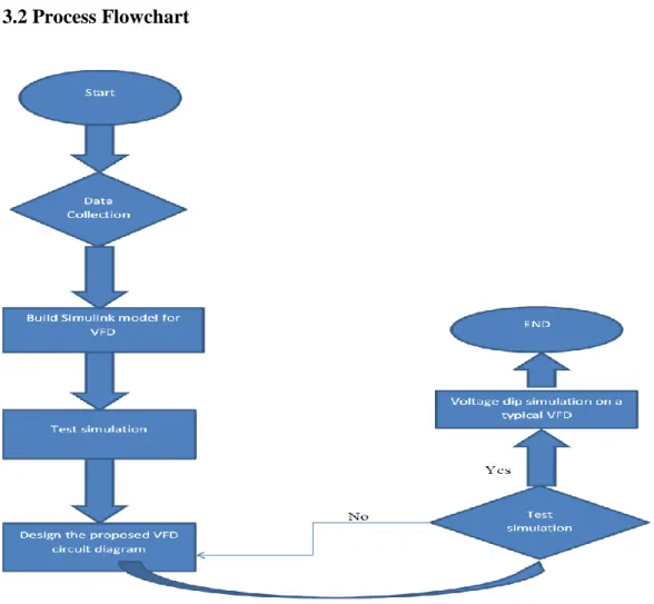
3.2 Process Flowchart
Figure 6: Methodology flow chart
17
The Figure 6 shows the sequence of events or tasks to be performed in order to successfully achieve the results of this study. The study started by doing research of previous papers and prepare a proper literature review. This step will be followed by the modeling of an existing VFD on Simulink, if the model is not verified; it will be checked and built again. If the model is verified the next step will be to implement a supercapacitor solution into the model. The proposed idea will be implemented in a circuit diagram. Simulink simulations will be used to test the effectiveness of the proposed design; this action will be repeated until optimal results are obtained. The last part of this experiment will be the discussion of the results obtained comparing them with the current designs.
3.3 System Modeling
3.3.1 Three-phase VFD model
This project aims at a single-phase VFD output, however, it is important to understand the behavior of a three-phase VFD under the influence of voltage dip. For instance, a three-phase VFD is modeled and simulated for both fault conditions: local and remote.
After completing the simulation of the three-phase model on Simulink, a supercapacitor is introduced in parallel with the internal capacitor of the VDF located in the DC-link.
The resulting model is simulated for both voltage dip conditions: local fault and remote fault. Figure 7 shows a three-phase VFD model circuit diagram connected to a three- phase motor as per the simulation.
18
Figure 7: Three-phase VFD circuit [1]
3.3.2 Single-phase VFD model
The lab facilities available for the project is made for single-phase VFD. In addition, the voltage dip generator available in the lab is of single-phase. A single-phase VFD model is built and simulated for remote and local fault conditions. The last part of the modeling of this project is the supercapacitor implementation on an existing VFD model and the posterior study of its performance using the settings available at lab.
In building the single-phase VFD model, the first part is to build a three-phase VFD model. Since the model of interest for this study is single-phase, the three-phase VFD model will be reduced to a single phase as shown in the Figure 8.
19
Figure 8: Single-phase converter with 4 pulse diode bridge [1].
The DC voltage as well as the working sequence delivered by the above diode rectifier are constantly changing as the supply line voltage also changes. No control circuit is applied, hence called Uncontrolled Diode Rectifier because the DC link bus voltage, or simply the DC voltage delivered by the diode is not subjected to any control.
3.4 Tools Overview
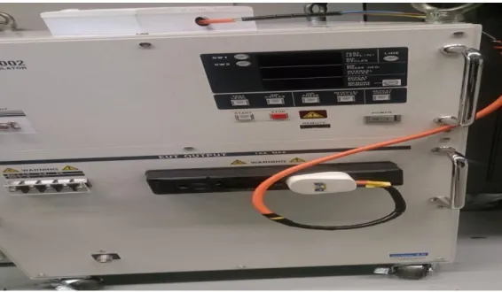
a) Voltage Dip Generator:
Figure 9 shows a single-phase voltage generator that will later be used in the lab experiment on an existing VFD. As one reason why this study is limited to single phase voltage, the voltage dip generator shown above is single phase, and only model available in the lab for this study.
20
Figure 9: Single-phase voltage dip generator
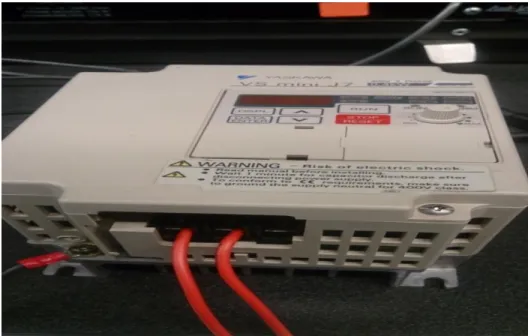
b) VFD: A single-phase output VFD will be used in this study to drive the induction motor available in the lab as shown in Figure 10.
Figure 10: Single-phase VFD
21
c) Induction Motor: Figure 11 shows the single-phase motor used in this study. For these machines, the rotor shaft moves slower than the synchronous speed. In this case the rotor will continue rotating the magnetic field, but at a lower speed. A speed difference of field and the rotor is called absolute slip.
Figure 11: Single-phase induction motor
d) MatLAB/SIMULINK: Simulink will be used to simulate both the existing and the proposed VFD models. Simulink is an application that allows to construct and to simulate models of systems physical and control systems using block diagrams. The behavior of such systems are defined by transfer functions, mathematical operations, Matlab elements and predefined ~ signals of all kinds.
Simulink has a series of utilities that facilitate the visualization.
22
3.5 Key Milestone and grant chart: TABLE 3 shows both the Key Milestone and grant chart of the project.
TABLE 3 Key Milestone and grant chart of the project
23
CHAPTER 4
RESULTS AND DISCUSSION
4.1 Introduction
The first part of this study involves simulation on the performance of the typical VFD model. In the second part, changes will be introduced in the model to meet the requirements and objectives of the project. A VFD Simulink model was built to simulate and observe the behavior a VFD under different load and fault conditions. This simulation was performed using specific values for voltage and frequency after some calculations. The following settings are established:
Table 4: Thee-Phase Induction Motor Settings
Nominal power, voltage and frequency [3*746, 220, 50]
Stator resistance and inductor [1.115 0.005974]
Mutual inductance 0,2037
Inertia constant, friction factor and pole pairs
[0.20, 0.005752 2]
The voltage source generates a voltage of 25 kV. This voltage is reduced to 380 V using step-down transformer.
24
The Figure 12 shows the VFD Simulink model. A programmable voltage source is used to generate supply phase voltage of 220 V. This voltage enters the VFD circuit where it is converted to DC using a converter circuit and later converted back to AC using IGBT converter block.
Figure 12: Typical VFD Simulink model
The output of the VFD is the controlled PWM voltage and the current that is supplied to the induction motor. Along the model, various measurement blocks have been place to take the readings accurately from the system.
4.2 Three-Phase VFD
4.2.1 Voltage Dip Simulation by Local Three-Phase Fault
A three-phase VFP was modeled on Simulink with a source RMS voltage of 220 V.
Therefore, local fault was generated at time 0.3 secs and cleared at 0.6 secs. The results are shown in Figure 13. It is observed that the voltage at the source drops to 70V for a voltage dip of 30 %, causing the VFD to trip as shown by the DC-link current, which
25
drops to 150 V. After the voltage dip is cleared, the DC-link voltage takes some time delay of less than 0.1 secs to be restored to its normal value.
Figure 13: VFD voltages during local three-phase fault
Figure 14 contains the current signals of a three-phase VFD when a local fault is applied. It is observed that when the motor starts, the inrush current is 6xIn, which is equal to 225 A. After a few miliseconds, the current is restored to its normal value, 37.5 A. Fault starts at 0.3 secs and it is cleared at 0.6 secs.
Figure 14: VFD currents during local three-phase fault
26
4.2.2 Voltage Dip Simulation by Remote Three-Phase Fault
A three-phase VFD was modeled on Simulink software with a source RMS voltage of 220 V. A remote fault was generated 3 km away at time 0.3 secs and cleared at 0.6 secs.
The results are shown in Figure 15. It is observed that the voltage at the source drops to 1200 V for a voltage dip of 70 %, causing the VFD to trip as shown by the DC-link current, which drops to 160 V. After the voltage dip is cleared, the DC-link voltage takes some time delay of less than 0.1 secs to be restored to its normal value.
Figure 15: VFD voltages during remote three-phase fault
Figure 16 shows current signals of a three-phase VFD when a remote fault is applied 3 km away. It is observed that when the motor starts, there is an inrush current of 6xIn, which is equal to 225 A. After a few miliseconds, the current is restored to its normal value, 37.5 A. Fault starts at 0.3 secs and it is cleared at 0.6 secs.
27
Figure 16: VFD currents during remote three-phase fault
4.2.3 Voltage Dip Simulation by Local Three-Phase Fault when VFD equipped with Supercapacitor.
Figure 17 shows the effect of a 1.5 F and 5.4 V supercapacitor on the VFD when voltage dip occurs. It can be seen that the DC-link voltage remains unchanged under the influence of a 50 % voltage dip. The DC-link current also remains above the threshold value as shown in Figure 18.
28
Figure 17: VFD voltages during local three-phase fault with supercapacitor . implementation
Figure 18: VFD currents during local three-phase fault with supercapacitor . implementation
29 4.3 Single Phase VFD
4.3.1 Voltage Dip Simulation by Local Single-Phase Fault
In Figure 19 it is observed that 220 V is the source voltage. 50 % voltage dip occurs at 0.3 seconds causing the voltage to drop from 220 V to 110 V. The DC-link Voltage, increases to 330 V from 0 seconds to 0.3 seconds. Fault occurs at 0.3 seconds, this decreases the DC-link voltage below the threshold value 220 V, causing the VFD to trip.
When fault is cleared at 0.6 seconds, the voltage will experience some transient state in the form of overshoot before it is restored to its normal value as shown in Figure 20.
Figure 19: VFD voltages during local single-phase fault
30
Figure 20: VFD currents during remote single-phase fault
4.3.2 Voltage Dip Simulation by Local Single-Phase Fault when VFD equipped with Supercapacitor.
Figure 21 shows that by adding a supercapacitor, the DC-link voltage is maintained above 220 V despite de voltage dip. This will allow the VFD to ride-through the voltage dip.
Figure 21: VFD voltages during local single-phase fault with supercapacitor implementation.
31
The VFD has managed to limit the large inrush current drawn by the motor when it is started. Figure 22 shows how fast the inrush current is limited and brought to normal value. A voltage dip occurs at 0.3 secs, however, the VFD will continue to maintain the value of the DC-link current above the threshold value, with a current of 12.7 A.
Figure 22: VFD currents during local single-phase fault with supercapacitor implementation
4.4 Voltage Ride through capability of a single-phase VFD without supercapacitor implementation
Figure 23 shows the experimental results of a single-phase VFD performance under the influence of voltage dip. It is observed that for voltage dip of 100 % to 90 % the VFD will continue running without tripping. For 80 % voltage dip, the VFD will trip after 0.5 seconds. For voltage dip of 70 % to 50 %, the VFD will trip after 0.2 seconds. Finally, for voltage dip less than 40 %, the VFD will trip after 0.04 seconds.
32
Figure 23: voltage Ride through capability of a single-phase VFD without supercapacitor implementation
4.5 Voltage Ride through capability of a single-phase voltage VFD with supercapacitor (1.5 F, 5.4 V) implementation
Figure 24 shows the simulation results of a single-phase VFD with a supercapacitor (1.5 F 5.4 V) implementation. The result shows that the VFD will not trip for a voltage dip of 100 % or 90 %. For voltage dip of 80 % to 60 %, the VFD will only trip after 90 seconds. For a voltage dip of 50%, the VFD will trip after 70 seconds. For 40 % voltage dip, the VFD will trip after 60 seconds and 50 seconds for a voltage dip of 30 %. For a voltage dip of less than 30 %, the VFD will trip after 40 seconds.
###
90 80 70 60 50 40 30 20 10 0
0.01 0.1 1 10 100
Remaining Voltage (%)
Duration of Voltage Dip (Seconds)
33
Figure Figure24: voltage Ride through capability of a single-phase VFD with supercapacitor implementation
###
90 80 70 60 50 40 30 20 10 0
0.01 0.1 1 10 100
Remaining Voltage (%)
Duration of Voltage Dip (Seconds)
34
CHAPTER 5
CONCLUSION
This study demonstrates the improvement of the voltage dip ride through capability of VFD with a supercapacitor placed in the DC-link. A broad understanding of motor operation when voltage dip occurs was necessary to design a VFD with the desired characteristics. The operation of the VFD and its behavior during voltage dip have been analyzed by both simulation and laboratory experiment. A 1.5 F and 5.4 V supercapacitor has been used to improve the ride through capability of a VFD and test for several capacitance values and observe the effectiveness of each, the highest capacitance value gives better ride through capability. It is observed that for voltage dip of 100 % to 90 % the VFD will continue running without tripping. For 80 % voltage dip, the VFD will trip after 0.5 seconds. For voltage dip of 70 % to 50 %, the VFD will trip after 0.2 seconds. Finally, for voltage dip less than 40 %, the VFD will trip after 0.04 seconds. A supercapacitor of 1.5 F and 5.4 V has been introduced in the DC-link of the VFD. This results in a VFD with higher ride-through capability. With the supercapacitor implementation, the VFD only trips for voltage dip of less than 30 % and after 60 seconds. Therefore, it is safe to declare that the results and objectives of this study have been successfully accomplished.
35
CHAPTER 6
RECOMMENDATIONS
VFD design improvement to survive during voltage dip is a critical and yet, exciting area of research, due to the importance of VFD operation to feed induction motors and other types of loads. It is essential to maintain the VFD running in an uninterruptible way, especially when there are power quality problems such as voltage dip. This paper provides and demonstrates the ride through capability of VFD when voltage dip occurs.
According to the simulations run, the ride through capability of a VFD increases significantly when a supercapacitor is placed in the DC-link of a VFD. This increases the capacitance of the DC-link, lowers the ripple and improves the ride through ability of a VFD. However, this study is limited to simulations, it is recommended that the results obtained from this study could be implemented in the laboratory with a VFD. A VFD with a physical DC-link should be used in order to ease the parallel connection of the supercapacitor circuit.
36
REFERENCES
[1] F. J. T. E. Ferreira, A. T. d. Almeida, and G. Baoming, "Impact of voltage sags and continuous unbalance on variable-speed drives," in Electrical Machines (ICEM), 2010 XIX International Conference on, 2010, pp. 1-6.
[2] J. K. Lawrence, "Generators and Motors," in Understanding Electro-Mechanical Engineering:An Introduction to Mechatronics, ed: Wiley-IEEE Press, 1996, pp.
67-87.
[3] C. K. Paul, W. Oleg, and D. S. Scott, "DirectCurrent Machines," in Analysis of Electric Machinery and Drive Systems, ed: Wiley-IEEE Press, 2002, pp. 67-107.
[4] C. K. Paul, W. Oleg, and D. S. Scott, "Brushless dc Motor Drives," in Analysis of Electric Machinery and Drive Systems, ed: Wiley-IEEE Press, 2002, pp. 557- 601.
[5] S. K. Swarn, "Rotating AC Machines," in Applications of High Temperature Superconductors to Electric Power Equipment, ed: Wiley-IEEE Press, 2011, pp.
59-128.
[6] C. Massimo and P. Davide, "Induction Machines and Drives," in Fundamentals of Electric Power Engineering:From Electromagnetics to Power Systems, ed:
Wiley-IEEE Press, 2014, p. 552.
[7] J. Zhang and P. F. Xie, "Modeling of AC Induction Motor Based on Saber and Time-domain Simulation Study for Its Drive System," 2015 Fifth International Conference on Instrumentation and Measurement, Computer, Communication and Control (Imccc), pp. 1429-1434, 2015.
[8] W. Kawamura, M. Hagiwara, and H. Akagi, "Design and Evaluation of AC Inductors Indispensable to a Modular Multilevel Cascade Converter (MMCC- TSBC) for Medium-voltage Motor Drives," 2015 Ieee 2nd International Future Energy Electronics Conference (Ifeec), 2015.
[9] G. Sivasankar and V. S. Kumar, "Improving Low Voltage Ride through Capability of Wind Generators Using Dynamic Voltage Restorer," Journal of Electrical Engineering-Elektrotechnicky Casopis, vol. 65, pp. 235-241, Jul-Aug 2014.
[10] G. Brando, L. P. D. Noia, R. Rizzo, D. Lauria, and C. Pisani, "An advanced system for power supply and power quality improvement of isolated AC passive network," in 2015 International Conference on Renewable Energy Research and Applications (ICRERA), 2015, pp. 1446-1450.
[11] K. Jadhav Prashant, V. R. Kanetkar, and S. K. Sahoo, "Supply power quality improvement using Steinmetz principle and network short circuit capacity," in 2015 Annual IEEE India Conference (INDICON), 2015, pp. 1-6.
[12] F. Valenciaga and R. D. Fernandez, "Multiple-input-multiple-output high-order sliding mode control for a permanent magnet synchronous generator wind-based system with grid support capabilities," IET Renewable Power Generation, vol. 9, pp. 925-934, Nov 2015.
![Figure 1: DC Motor Operation [4]](https://thumb-ap.123doks.com/thumbv2/azpdforg/11143985.0/16.918.184.840.203.424/figure-1-dc-motor-operation-4.webp)
![Figure 2: Schematic VFD diagram [9].](https://thumb-ap.123doks.com/thumbv2/azpdforg/11143985.0/20.918.187.800.552.757/figure-2-schematic-vfd-diagram-9.webp)
![Figure 3: Spectrum of a signal with different types of waveform distortion[11]](https://thumb-ap.123doks.com/thumbv2/azpdforg/11143985.0/21.918.299.686.760.1020/figure-spectrum-signal-different-types-waveform-distortion-11.webp)
![Figure 4: Voltage dip profile [1].](https://thumb-ap.123doks.com/thumbv2/azpdforg/11143985.0/23.918.168.770.152.392/figure-4-voltage-dip-profile-1.webp)
![Figure 5: Required Semiconductor equipment voltage ride-through capability [7].](https://thumb-ap.123doks.com/thumbv2/azpdforg/11143985.0/24.918.203.842.216.500/figure-5-required-semiconductor-equipment-voltage-ride-capability.webp)
![Figure 7: Three-phase VFD circuit [1]](https://thumb-ap.123doks.com/thumbv2/azpdforg/11143985.0/29.918.240.750.109.322/figure-7-three-phase-vfd-circuit-1.webp)
![Figure 8: Single-phase converter with 4 pulse diode bridge [1].](https://thumb-ap.123doks.com/thumbv2/azpdforg/11143985.0/30.918.229.778.107.360/figure-8-single-phase-converter-pulse-diode-bridge.webp)