The main purpose of the shear connections installed in the composite column is to transfer axial load between concrete and steel member. The size of the CFST column is (2000x2000x100) at the interface with the Transfer plate, which has been considered in the design of the column under gravity and biaxial bending.
INTRODUCTION
COMPOSITE ELEMENTS DESIGN AND CONSTRUCTION
Increase the bearing capacity of the columns without significantly increasing the dimensioning of the columns. Provide smaller dimensions of the columns compared to conventional reinforced concrete columns, which is a crucial requirement of the architect.
ENCASED STEEL REINFORCED COMPOSITE COLUMN (SRC)
Utilize the full benefits of both materials, a high-strength steel section with proper formability contributes to the load-bearing capacity and formability of the concrete. If both sections of concrete and steel are partially connected or if there is no connection between steel and concrete, relative slip may occur at the interface level, and as a result the stress distribution of the concrete and steel will not be compatible.
CONCRETE FILLED STEEL TUBE COLUMN (CFST)
1.4) Local buckling mode for the diameter of the concrete-filled tube. 1.5) Elastic local buckling change along the length of the concrete-filled tube.
RESEARCH SIGNIFICANCE
RESEARCH CHALLENGE
RESEARCH OBJECTIVE
CASE STUDY
The depth of the transfer slab was 2.50 m and it holds about 50 stories above the transfer level. The grade of steel used in this element was S355, and the armor was equipped with a grade of 500MPa.
SCOPE
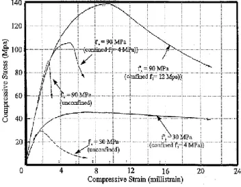
The yield strength of the steel pipe was 310 MPa and the concrete strength was 119 MPa. The stress-strain relationship of the steel pipe is calculated from the test output.
LITERATURE REVIEW
INTRODUCTION
ADVANCE TECHNOLOGY OF CONSTRUCTION MATERIAL
HIGH STRENGTH AND HIGH-PERFORMANCE CONCRETE
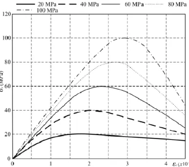
The stress-strain relationship formula for the high-strength concrete has been developed by [Collins & Mitchell, 1991] as follows:. The failure mode of the high-strength concrete is more brittle than conventional concrete, which has a high ductility.
CONCRETE MODULUS OF ELASTICITY (YOUNG’S MODULUS)
HIGH STRENGTH AND HIGH-PERFORMANCE STEEL
High performance steel exhibits less inelastic elongation than conventional steel as a result of its lower ductility in deformation. High performance steel flexural members have a small ratio of peak moment to plastic moment compared to conventional steel members [Ricles et al., 1996].
![Fig. 2.3 Stress-Strain Relationship Curve for High Performance Steel and Conventional Steel [Salmon and Johnson, 1996]](https://thumb-ap.123doks.com/thumbv2/azpdfco/10391112.0/39.893.281.629.76.382/stress-strain-relationship-curve-performance-conventional-salmon-johnson.webp)
BEHAVIOR OF CONFINED CONCRETE IN THE COMPOSITE COLUMN
BOND BETWEEN STEEL AND CONCRETE
COMPOSITE DESIGN PROVISION IN ACCORDANCE WITH AMERICAN SPECIFICATIONS
- ACI PROVISION FOR COMPRESSIVE STRENGTH OF COMPOSITE COLUMN
- ANCI / AISC PROVISION FOR COMPRESSIVE STRENGTH OF ENCASED COMPOSITE COLUMN
- ANCI / AISC PROVISION FOR COMPRESSIVE STRENGTH OF CONCRETE FILLED STEEL TUBE
- ACI PROVISION FOR COMBINED FLEXURE AND AXIAL FORCES
- ANCI / AISC PROVISION FOR ENCASED COMPOSITE AND FOR FILLED COMPOSITE WITH
- ANCI / AISC PROVISION FOR FILLED COMPOSITE WITH NONCOMPACT OR SLENDER SECTIONS
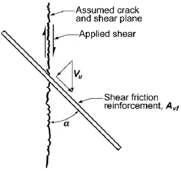
- LOAD TRANSFER
- MECHANISM OF FORCE TRANSFER
- Direct Bearing Force Mechanism
- Direct Bond Interaction Mechanism
- Shear Connection Force Mechanism
- Tensile Strength of Steel Headed Stud Anchor in Composite Members
- Shear Strength of Steel Channel Anchors in Composite Members
- Detailing Requirements for Steel Studs and Anchors in Composite Elements
In the event that the forces are transferred by shear connection for cased composite or filled composite, the ultimate shear strength of the steel head stud or steel channel anchors can be calculated from the following formula:. 2.39). The design shear strength (ØQnv) can be calculated from the following formula if the breaking strength of the concrete does not determine the shear strength.
COMPOSITE DESIGN PROVISION IN ACCORDANCE WITH EUROCODE 4 SPECIFICATIONS
- EUROCODE 4 DESIGN PROVISION FOR COMPOSITE COLUMN SUBJECT TO AXIAL COMPRESSION
- EUROCODE 4 DESIGN PROVISION FOR COMPOSITE COLUMN SUBJECT TO AXIAL COMPRESSION
- EUROCODE 4 DESIGN PROVISION FOR COMPOSITE COLUMN SUBJECT TO AXIAL COMPRESSION
- TRANSFER SHEAR FORCES EFFECT ON THE COMPOSITE COLUMN DESIGN RESISTANCE
- EUROCODE PROVISION FOR THE P-M INTERACTION DIAGRAM
- EFFECTIVE FLEXURE STIFFNESS OF THE COMPOSITE COLUMNS
- SECOND ORDER INFLUENCE, GEOMETRICAL, AND MEMBER IMPERFECTIONS
- CRITICAL BUCKLING LOAD ON THE COMPOSITE COLUMN
- EUROCODE 4 PROVISION FOR SHEAR FORCES TRANSFER
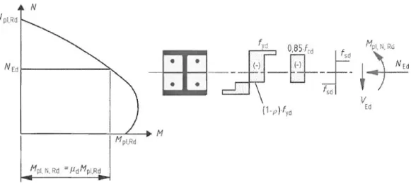
Ncr The critical load causes buckling for the column related to the effective stiffness of the composite column (EL)eff. Point (C) represents the intersection between plastic resistance of the composite element in bending and the design resistance of the Concrete Section against axial compressive loading. Point (D) represents the intersection between plastic resistance of the composite section against bending and half of the concrete resistance against axial pressure [0.50 Npm,Rd].
The effective bending stiffness of the composite column diameter [EI]eff must be calculated to determine the relative stiffness [λ], the axial compressive load that leads the column to bend, and long-term effect on the properties of the concrete [ Kruip &. The critical [Euler] buckling load can be calculated considering the end conditions of the composite columns. The longitudinal reinforcement for encased composite column shall not be less than 0.30% of the concrete diameter.
ISOLATED STEEL REINFORCED CONCRETE COLUMN (ISRC)
PRECEDING AND CURRENT RESEARCHES ON THE CONCRETE FILLED TUBE COLUMNS
4.6) presents the stress contours along the height of the enveloped columns as extracted from the 3D Fiber (Solid) Model. 4.7) presents the stress contours along the height of the enveloped columns as extracted from the 3D Fiber (Solid) Model. 4.8) presents the stress contours along the height of the enveloped columns as extracted from the 3D Fiber (Solid) Model.
4.9) presents the stress contours along the height of the encapsulated columns as extracted from the 3D Fiber (Solid) Model. 4.17) presents the stress contours along the height of the CFST columns as extracted from the 3D Fiber (Solid) Model. 4.19) presents the stress contours along the height of the CFST columns as extracted from the 3D Fiber (Solid) Model.
![Fig. 2.22 Tomii and Skino’s Model of Confined Concrete utilized by Zhang and Shahrooz [1997]](https://thumb-ap.123doks.com/thumbv2/azpdfco/10391112.0/95.893.218.665.690.1037/tomii-skino-model-confined-concrete-utilized-zhang-shahrooz.webp)
RESEARCH METHODOLOGY
INTRODUCTION
Furthermore, it presents the experimental approach versus the theoretical one by performing a study for 1/5 scale columns compared to the actual size extracted for the case study.
RESEARCH APPROACH
RESEARCH STRATEGY
Demonstrate a case study and the actual stressing actions on the composite columns used in this research. Theoretical analysis of the 1/5 scale column model compared to the actual size specified in the case study using appropriate software. Comparison of theoretical results between the 3D fiber (solid) model and the simplified method adopted by AISC316-16, ACI 318-11 and Eurocode-4.
DATA COLLECTION
The analysis shown in the table below [4.6] was performed using Concrete Cylinder Strength of C40MPa, and Steel Grade of S275MPa. 4.10) presents the stress contours along the height of the enveloped columns as extracted from the 3D Fiber (Solid) Model. The analysis shown in the table below [4.7] was performed using Concrete Cylinder Strength of C50MPa, and Steel Grade of S275MPa. 4.11) presents the stress contours along the height of the enveloped columns as extracted from the 3D Fiber (Solid) Model. The analysis shown in the table below [4.8] was performed using Concrete Cylinder Strength of C60MPa, and Steel Grade of S275MPa. 4.12) presents the stress contours along the height of the enveloped columns as extracted from the 3D Fiber (Solid) Model.
The analysis in the table below [4.9] was performed with a concrete cylinder strength of C70MPa and steel grade of S275MPa. 4.13) presents the stress contours along the height of the encapsulated columns as extracted from the 3D Fiber (Solid) Model. The analysis in the table below [4.19] was performed with a concrete cylinder strength of C40MPa and steel grade of S355MPa. 4.23) presents the stress contours along the height of the encapsulated columns as extracted from the 3D Fiber (Solid) Model. The analysis in the table [4.20] below was performed with a concrete cylinder strength of C50MPa and steel grade of S355MPa. 4.24) presents the stress contours along the height of the encapsulated columns as extracted from the 3D Fiber (Solid) Model.
RESEARCH RESULTS
INTRODUCTION
This chapter presents the numerical analysis of tapered CFST columns connected with closed composite (SRC) columns according to a selected case study of an existing high-rise building in Dubai, UAE. It then provides a numerical analysis of a 1/5 scale column model under different types of loading with different concrete compressive strengths. Results from 3D finite element models will be compared with simplified formulas adopted by Eurocode-4, AISC/ANCI and ACI318-11.
The results show the distribution of stresses and strains along the height of the column under different types of loading, uniaxial compression, axial compression with unidirectional moments and axial compression with bidirectional moments.
CASE STUDY
The composite column is subjected to axial compressive loads and biaxial bending moments at the upper edge, while it is mainly subjected to axial forces at the lower edge with a significant reduction in bending moments compared to the upper part. It should be noted that the bending moments in the (X) direction at the bottom of the closed section are 11.9% of the bending moments at the top of the CFST column, while the bending moments in the (Y) direction are at the bottom of the closed section. of the section is about 4.4% of the bending moments at the top of the CFST section. Table [4.1] summarizes the deformation factors along the height of the column to provide a clear understanding of the deformation diagrams according to changing the size of the conical column section and changing the type of composite columns.
The ultimate axial force is equal to 33% of the nominal compressive strength of the CFST column. As illustrated in the literature review, CFST provides greater capacity for axial and bending compared to the encapsulated composite section, so it was an effective solution to change the column section from encapsulated section to CFST section for only one level instead of having CFST column at all levels from The foundations for the Transfer floor. The challenge with this idea was to assemble the CFST column components and to provide a rigid and appropriate connection detail to the transfer plate and the encased column section to ensure a smooth load path to the tapered CFST through the Transfer Plates and.
SIMPLIFIED METHOD FOR THE CFST COLUMN CAPACITY OF THE CASE STUDY
- ANCI / AISC PROVISION
- EUROCODE 4 PROVISION
RESEARCH DESIGN MODEL
- BOUNDARY CONDITIONS
- COLUMN RESISTANCE TO AXIAL COMPRESSION LOADS
- Stresses on the Encased Composite Column subject to Axial Compression Loads
- Stresses on the CFST Composite Column subject to Axial Compression Loads
- Stresses on the Stiffener Plates Welded to CFST & Encased under Axial Compression Load
- COLUMN RESISTANCE TO AXIAL COMPRESSION AND UNI-DIRECTION MOMENTS
- Stresses on the Encased Column subject to Axial Compression and Uni-Direction Moments….165
- Stresses on the CFST Composite Column subject to Axial Compression and Bi-Axial
- Stresses on the Stiffener Plates welded to the CFST and Encased Element, under Axial
The analysis shown in the table below [4.10] has been carried out with concrete cylinder strength of C40MPa and steel grade of S355MPa. 4.14) presents the stress contours along the height of the CFST columns as extracted from the 3D Fiber (Solid) Model. The analysis shown in the table below [4.11] has been carried out using concrete cylinder strength of C50MPa and steel grade of S355MPa. 4.15) presents the stress contours along the height of the CFST columns as extracted from the 3D Fiber (Solid) Model. The analysis shown in the table below [4.12] has been performed using concrete cylinder strength of C60MPa and steel grade of S355MPa. 4.16) presents the stress contours along the height of the CFST columns as extracted from the 3D Fiber (Solid) Model.
The analysis shown in the table below [4.14] was performed using a concrete cylinder strength of C40 MPa and a steel grade of S275 MPa. 4.18) represents stress contours along the height of CFST columns as extracted from the 3D Fiber (Solid) model. The analysis shown in the table below [4.21] was performed using a concrete cylinder strength of C60 MPa and a steel grade of S355 MPa. 4.25) represents the stress contours along the height of the clad columns as extracted from the 3D Fiber (Solid) model. The analysis shown in the table below [4.22] was performed using a concrete cylinder strength of C70 MPa and a steel grade of S355 MPa. 4.26) represents the stress contours along the height of the clad columns as extracted from the 3D Fiber (Solid) model.
The analysis shown in the table below [4.23] has been carried out using concrete cylinder strength of C40MPa and steel grade of S275MPa. 4.27) presents the stress contours along the height of the encased columns as extracted from the 3D Fiber (Solid) Model. The analysis shown in the table below [4.24] has been carried out using concrete cylinder strength of C50MPa and steel grade of S275MPa. 4.28) presents the stress contours along the height of the encased columns as extracted from the 3D Fiber (Solid) Model.
DISCUSSION OF RESULTS
INTRODUCTION
COMPOSITE COLUMN BEHAVIOR SUBJECT TO CONCENTRIC AXIAL COMPRESSION LOAD
- Encased Composite Column Subject to Concentric Axial Compression Load
- CFST Composite Column Subject to Concentric Axial Compression Load
- Steel Stiffener Plates Behavior connected to CFST and Encased Column under Concentric Axial
COMPOSITE COLUMN BEHAVIOR UNDER AXIAL COMPRESSION AND UNI-DIRECTION BENDING…
- Encased Composite Column Subject to Axial Compression and Uni-direction Bending
- CFST Composite Column Subject to Axial Compression and Uni-direction Bending
COMPOSITE COLUMN BEHAVIOR UNDER AXIAL COMPRESSION AND BI-AXIAL BENDING
- Encased Column Subject to Axial Compression and Bi-Axially Bending Moments
- CFST Composite Column Subject to Axial Compression and Bi-Axially Bending Moments
- Steel Stiffener Plates Behavior connected to CFST and Encased Column under Axial Compression
SUMMARY AND CONCLUSION
COMPOSITE COLUMN SUBJECT TO UNI-AXIAL COMPRESSION LOAD
COMPOSITE COLUMN SUBJECT TO COMBINED AXIAL COMPRESSION AND UNI-
COMPOSITE COLUMN SUBJECT TO COMBINED AXIAL COMPRESSION AND BI-DIRECTION
RECOMMENDATION FOR DESIGN AND FUTURE RESEARCHES
- Design Recommendations
- Research Recommendations
APPENDICES

![Fig. 2.5 Three Different Confinement zones in the Encased Composite Column, [Chen and Lin, 2006]](https://thumb-ap.123doks.com/thumbv2/azpdfco/10391112.0/41.893.154.742.501.755/fig-different-confinement-zones-encased-composite-column-chen.webp)
![Fig. 2.6B Confinement Factor for Highly Confined Concrete, [Chen and Lin, 2006]](https://thumb-ap.123doks.com/thumbv2/azpdfco/10391112.0/42.893.329.685.594.982/fig-confinement-factor-highly-confined-concrete-chen-lin.webp)
![Fig. 2.6A Confinement Factor for Partially Confined Concrete, [Chen and Lin, 2006]](https://thumb-ap.123doks.com/thumbv2/azpdfco/10391112.0/42.893.295.635.161.500/fig-confinement-factor-partially-confined-concrete-chen-lin.webp)