42 Table 5: Summary of proposed system processing improvements in terms of number of cell voltage samples obtained. 48 Table 7: Summary of proposed system processing improvements in terms of comparisons obtained with the proposed approach versus the classical one.
- Overview
- Importance and Motivation
- Aim & Objectives
- Problem Statement
According to [4], the performance of remote and integrated power systems has improved recently. Furthermore, the performance of these systems can also be further improved through proper system management and monitoring, especially batteries [4].
Power Management System in PS
- Importance of power management system in PS
Event Driven Data Acquisition
Lithium-Ion Battery
- Importance of Lithium-Ion Battery
- Lithium-Ion Battery Applications
- Lithium-Ion Battery Technology
It is very essential to note that the safe operating condition of a battery in PS cannot be determined only during direct measurements, but also depends on the condition of the battery at that time. The state of the battery which is often used to approximate the expected life of the battery can be specified using two parameters, ie State of Charge (abbreviated as SoC) and State of Health (abbreviated as SoH). In [21], the authors stated that the state of charge of a battery (SoC) is the current state of charge of a battery and depends on the initial state of charge of the battery and the current in and out at a certain temperature.
Furthermore according to [21], the condition of the battery reflects the ability of the battery to deliver a specified performance compared to a fresh battery. The most important electrical parameters that are often monitored during the discharge and charge of a battery pack in PS are current, ambient temperature during the charge and discharge cycles, voltage and internal resistance of the battery [21].
![Figure 2: Schematic diagram of a lithium-ion battery [10]](https://thumb-ap.123doks.com/thumbv2/azpdfco/10329825.0/20.918.239.748.372.618/figure-schematic-diagram-lithium-ion-battery.webp)
Battery State of Charge (SoC)
Therefore, it is important that the battery pack of a remote and integrated PS is monitored during discharge and charge conditions. Therefore, the smooth operation of a remote and integrated PS depends on the accuracy of the state of charge and state of health monitoring systems [21]. The conventional method uses physical properties of the battery such as discharge current, resistance, voltage and impedance to estimate a battery's state of charge [10].
The adaptive filter algorithm uses a number of models and data when estimating the state of charge of the battery [10]. On the other hand, the learning algorithm uses large quantities and heavy calculations in describing the nonlinear properties of lithium-ion systems and in estimating the state of charge [24].
Summary of Literature Review and The Related Studies
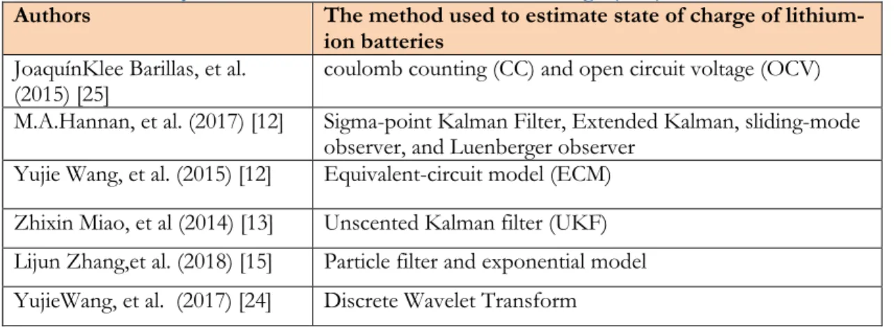
The ECM includes the acceptance of the Kalman filter as the best performance that helps achieve an optimal estimate [13]. Accurate SoC estimation and reliability in real time is essential in the battery management systems [12]. It reduces data acquisition module activity and electronics level complexity and also improves the efficiency of the post-signal processing and data transmission modules by reducing their computational complexity and transmission activity, respectively.
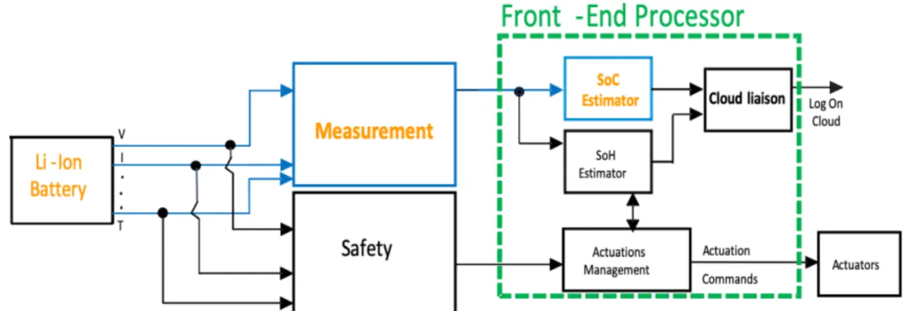
In the proposed study, the idea is to use an efficient (BMS) that consists of different modules for the whole framework of the system. Figure 6 illustrates the principle of the proposed system. The output of the safety modules that is transmitted through the system to the front controller that uses this incoming data to make a trigger decision, such as some changes in the actuators, for example, as a last resort, it will isolate the battery from the intersystem, depending on the condition, such as rise in temperature by a certain limit, increase in current values or exceed a certain threshold for humidity.
The Battery Model
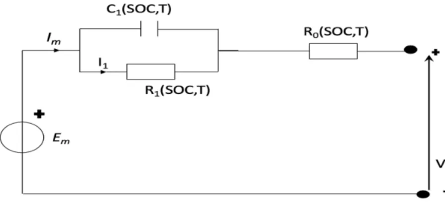
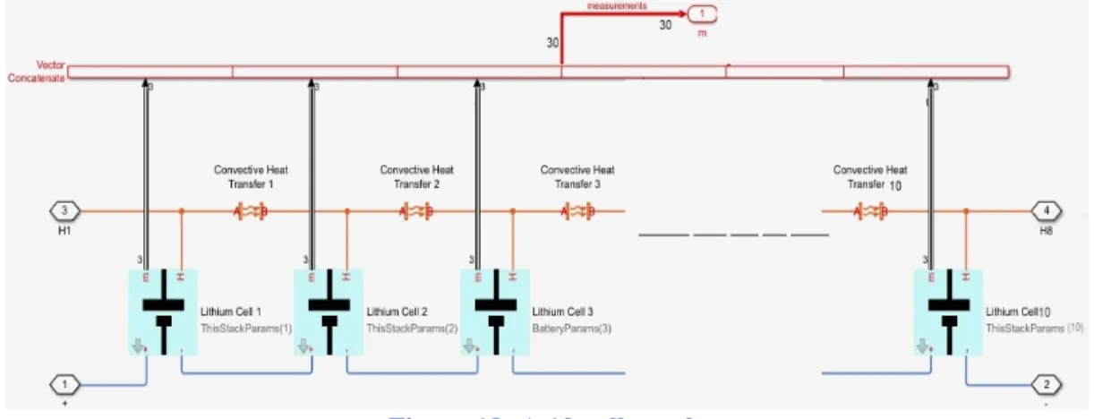
The majority of the models used in the current literature have not accounted for the thermal effects. In the proposed solution [26], the limitations are overcome by applying temperature as an independent variable, as seen in the Lookup Table used to define the elements of the circuit. The parameter estimation procedure showed dependencies of the equivalent circuit elements on SoC and temperature, which were consequently implemented as Lookup Tables that described the equivalent values of the circuit elements.
28 capacitive component of RC), and R0 (ohmic internal resistance), R1 (The resistive component of RC element), which changes with SoC and temperature in the cell [26]. The temperature of the inner cells is assumed to be similar values, as the average cell temperature.
![Figure 7: An equivalent circuit for general model [24],[27] of an electrochemical-cell The number of equivalent circuit parts as an outcome in a trade-off between both complexity and fidelity](https://thumb-ap.123doks.com/thumbv2/azpdfco/10329825.0/28.918.232.753.113.318/figure-equivalent-circuit-general-electrochemical-equivalent-complexity-fidelity.webp)
Battery Model Parameters Estimation
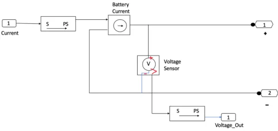
The recordings of battery parameters such as current, voltage and temperatures are realized using event-driven measurements. One of the most vital elements affecting BMS efficiency is monitoring the battery voltage and current. It prevents the battery from being overcharged and discharged, which can result in rapid aging or even an explosion of the battery.
For threshold-crossing conditions, a sample is taken just after the input band-limited analog signal x(t) crosses one of the predefined thresholds. The main features and advantages are three, first is the reduction of the activity, second is the reduction of electromagnetic emission and the last advantage is the reduction of power consumption.
The Battery State of Charge Estimation
Moreover, the instantaneous sampling is precisely known for traditionally ideal ADCs, while the sample amplitudes are quantized and determined by the number of ADC bits [30], [34]. This error is considered by the SNR (Signal to Noise Ratio) [34], which is explained by equation (4). For the ideal ADC, the SNR depends only on R and may very well increase by 6.02 dB for each increase in R.
An improvement in SNR values of 6.02 dB can be easily achieved by dividing T-timer by a factor of two. The Battery Management System (BMS) must also perform an accurate runtime SoC estimation to ensure that the battery packs achieve adequate cell balance.
Real-Time Determination of The Sate of Charge (SoC)
- Discrete Time Coulomb Counting Algorithm
From the above information it can be stated that the SoC rating is based on Ib and Vb, while the operating mode of the battery is known by the discharge mode. Additionally, Accuracy can be obtained from the accuracy of measurement of charge/discharge parameters and improved SoC estimation performed in case the battery is charged and discharged frequently. In modern BMSs, battery parameters such as voltage, temperature and current are no longer processed in the analog domain and are digitized and later processed with state-of-the-art digital processing algorithms [16], [14].
For this case, sF(t) can be expressed as a series of uniformly spaced infinite delta pulses. Shannon has proved that if x(t) does not contain a frequency greater than fmax, it can be completely reconstructed by giving its ordinates at some series points spaced 1/(2.fmax) second apart.
Discrete Time SOC-OCV Calibration
Because of this feature, this sampling process is also known as the periodic or the equal sampling process. Following the discussion above, in the classical case, the sampling version of Ib(t), can be presented by Equation (17). Therefore, in this case the Creleased, between the time interval [t0; t1] seconds can be calculated using equation (18).
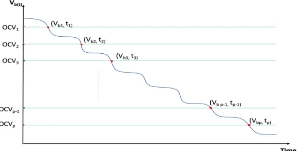
Transients can lead to a miscalibration of the SoC, which is usually compensated for by determining the slope of the cell voltage. In case of a consecutive bipolar slope, the calibration of the SoC is carried out towards subsequent measurements.
Event-Driven Coulomb Counting Algorithm and SoC-OCV Calibration
- Event-Driven Coulomb Counting Algorithm
- Event-Driven SoC-OCV Calibration
- The Computational Complexity
- The SoC Estimation Error
The computational complexity of the classical coulomb count and SoC-OCV calibration process is straight forward to calculate. Let FsI be the sampling frequency in the system for acquiring the cell current. Let FsV be the sampling frequency in the system for obtaining the cell voltage.
Therefore, the overall computational complexity of the coulomb count and SoC-OCV calibration processes can be calculated using Equation (26). Therefore, the overall computational complexity of the event-driven coulomb count and the event-driven SoC-OCV calibration processes can be calculated using Equation (27).
The Real-Time State of Charge (SoC) estimation of a High-Power Li-Ion
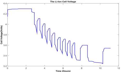
In this example, for the considered time span of 11.11 hours, EDADC acquires a total of 700 current samples. The cell voltage is obtained for the SoC estimation calibration procedure based on the SoC-OCV lookup table. In this example, for the considered time span of 11.11 hours, the EDADC acquires a total of 73 voltage samples.
Furthermore, in the proposed solution the used EDADCs have much less resolutions, 5-bit and 2.86Bit respectively for the cell current and the cell voltage acquisition. However, in the classical case, 12-bit ADCs are used to obtain the cell current and voltage.
Case Study for a Real-Time State of Charge (SoC) Estimation of a Li-Ion
It results in 2.5% MPSoCE for the classical estimator and 4.6% MPSoCE for the event-driven estimator. Its rated capacity is 31AH at an ambient temperature of 20oC. The ECM is created using SimscapeTM blocks and SimscapeTM language [26],[35]. These voltage curves can also be used for cell balancing of the battery pack [26],[33].
In this example, for the considered time span of 11.11 hours, the total voltage samples obtained by the EDADC for each cell in the battery pack are shown in Figure 22. Then, for the considered time span of 11.11 hours, the result will be N =40M samples for the current cells.
It provides a drastic reduction in system hardware level complexity compared to the traditional counterpart [18], [19]. The above results confirm a good performance of the suggested solution in terms of reducing electricity consumption and hardware design complexity compared to traditional benchtop solutions. This discussion describes a strong integration potential of the created solution in modern and stand-alone BMS.
Calibration and application of the proposed method to other batteries based on lithium-ion technology is another future task. A new method for evaluating the degradation and state of charge of lithium-ion batteries used for electric vehicles. Mohamed, "Review of Li-ion Battery State of Charge Assessment and Management System in Electric Vehicle Applications: Challenges and Recommendations".
Remaining useful life prediction for lithium-ion batteries based on exponential model and particle filter. Song, “The current move of lithium-ion batteries to the next phase,” Advanced Energy Materials, vol.
![Figure 1: A schematic diagram of wind-solar hybrid standalone power system [2]](https://thumb-ap.123doks.com/thumbv2/azpdfco/10329825.0/15.918.223.864.532.775/figure-schematic-diagram-wind-solar-hybrid-standalone-power.webp)
![Figure 3: The major components of Battery management system [10]](https://thumb-ap.123doks.com/thumbv2/azpdfco/10329825.0/21.918.208.762.114.485/figure-major-components-battery-management.webp)
![Figure 4: Block Diagram of Battery management system [10]](https://thumb-ap.123doks.com/thumbv2/azpdfco/10329825.0/21.918.187.804.523.964/figure-block-diagram-battery-management.webp)
![Figure 5: An architecture of battery State of charge estimation mechanism [21]](https://thumb-ap.123doks.com/thumbv2/azpdfco/10329825.0/23.918.215.783.111.444/figure-architecture-battery-state-charge-estimation-mechanism.webp)