He is the author or co-author of more than 150 scientific papers focused on the design and optimization of the parameter analysis of electrical machines. It is possible to investigate transient and steady states of electrical machines by means of this theory, see [7–9].
Inductances
Magnetizing inductance
This relationship applies to machines without ventilation ducts and takes into account the magnetic flux distribution at the end of the machines [1]. The effective air gap δe includes both the Carter factor and the effect of the saturation of the magnetic circuit.
Leakage inductance
The air gap leakage inductance can also be expressed by the air gap leakage factor:. The tooth tip leakage inductance of the entire phase winding is given by using Eq.
Resistances
The air gap diameter of the machine in example 2 is 130 mm and the total height of the slots is 22 mm. The gap leakage inductance of the 5/6 short winding in Example 2 is 0.304 mH, so it can be seen that the gap leakage inductance is much higher than the leakage inductance of the final winding.
Influence of skin effect on winding resistance and inductance .1 Influence of skin effect on winding resistance
Influence of skin effect on the winding inductance
To express the reduction of the inductance, the so-called skin effect factor kLis was introduced. To calculate the skin effect factor we need to define the reduced conductor height:. where bcis is the conductor width in the gap, σ is the specific material conductivity of the conductor, and ω is the angular frequency of the investigated current.
Introduction to the general theory of electrical machines
On the other hand, this assumption can have a significant impact on the accuracy of the results. Next will be given an arrangement of the universal machine on the basis of which the general theory was derived.
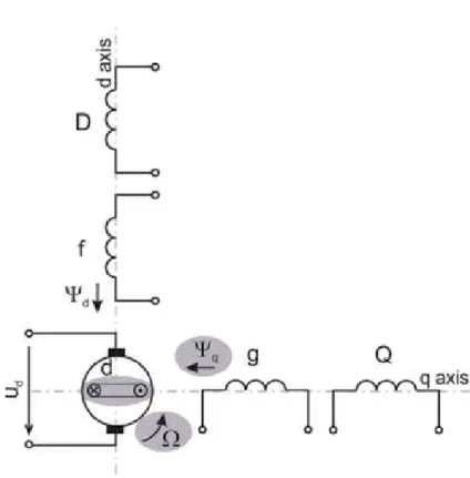
Design arrangement and basic equations of the universal machine in the general theory
Voltage equations in the system dq0
A movement of the q-winding in the marked direction (Figure 9) causes no rotating induced voltage from ψq, because the conductors of the q-winding do not cross magnetic lines of force ψq; they just move over them. The rotating voltage in d-winding is induced only by crossing magnetic lines of force of theψq (Figure 10).
Power in the system dq0 and electromagnetic torque of the universal machine
The expression on the left shows a rise of the delivered energy during the time dt:Σuidt. The second expression on the right is an increase of the field energy: Σidψ.
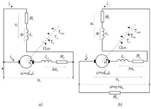
Application of the general theory onto DC machines
- Separately excited DC machine
- Shunt wound DC machine
- DC series machine
- Compound machines
- Single-phase commutator series motors
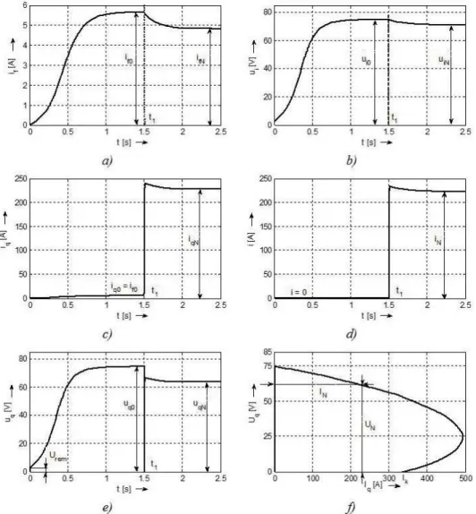
Simulation of a separately excited dynamo: time waveforms of (a) field current, (b) induced voltage, (c) armature current, (d) developed electromagnetic torque, (e) terminal voltage and (f) dependence of terminal voltage on load current in stationary conditions (external characteristic). Shunt dynamo simulations: time waveforms of (a) field current, (b) induced voltage, (c) armature current, (d) load current, (e) terminal voltage, and (f) counter terminal voltage.
Transformation of the three-phase system abc to the system dq0 .1 Introduction
Equations of Park’s transformations abc into dq0 system
It is seen that the projections to the q-axis are expressed by the sinusoidal function of the phase variable with a negative sign, at the given +q-axis (see Eq. If the three-phase system is symmetrical, the sum of the instantaneous values is zero; therefore, zero -component also zero (see Eq.
Equations for the m-phase system transformation
Graphical interpretation of the three-phase variable transformation abc in the reference k-system dq0, rotating at the speed ωk. Now the phases are marked 1, 2, 3, etc., to express the m-th phase and to see how the function's argument is made:.
Inverse transformation from dq0 to the abc system
Equations of the linear transformation made by means of the space vectors of the voltage and currents
Stator variable transformation
In Figure 25, a complex plane is graphically illustrated with the stator axis, which is now identical to the axis of the a-phase winding. Between the rotor axis and -axis of the k-reference frame there is an angleðϑk�ϑrÞ.
Voltage equations of three-phase machines and their windings The same equations as for the terminal voltage of the universal machine (63) can
In general, the space vector of the rotor voltage converted to the k-system can be written as follows:. The equations are the voltage equations for the stator windings of three-phase machines, such as induction motors in the k-reference system, rotating at an angular velocity ωk with an axis dq0.
Three-phase power and torque in the system dq0 .1 Three-phase power in the system dq0
Electromagnetic torque of the three-phase machines in the dq0 system As it is known, an air gap power can be expressed by the product of the devel-
An instantaneous value of the developed electromagnetic torque is valid: and after a torque reduction is:. An electromagnetic torque developed in rotating electric machines is directly related to the balance of torques acting on the shaft.
Power invariance principle
This is the base expression for the power, which is converted from an electrical to a mechanical form in the car or from a mechanical to an electrical form in the case of the generator. As it is known, an air gap force can be expressed by the product of the developed electromagnetic torque and a mechanical angular speed, now in the k-system:. or by means of electrical angular speed:. where p is the number of pole pairs.
Properties of the transformed sinusoidal variables
2cosðωst�ϑkÞ: (199) The stress in the q-axis is shifted from the stress in the d-axis by about 90°, which coincides with the definition of the d-axis and q-axis positions, which are perpendicular to each other. 3.Variables of the zero component, that is, with the subscript 0, are, in the case of the symmetric system, zero.
Choice of the angle ϑ k and of the reference k-system position The final form of the voltage equations in the system dq0 does not depend only
Additionally, here are the equations for an electromagnetic torque and time varying with angular velocity. This choice means that system k is identified with the rotor axis and the speed of system k with the rotor speed.
Asynchronous machine and its inductances
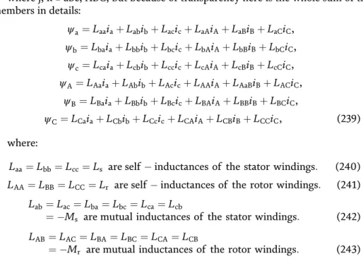
Inductances that do not depend on the rotor position 1. Self-inductances of the stator windings L s
Laa¼Lbb¼Lcc¼Ls are the intrinsic inductances of the stator windings: (240) LAA¼LBB¼LCC¼Lr are the intrinsic inductances of the rotor windings: (241). The same analysis as in point 3 leads to the conclusion that the mutual inductance of the rotor windings without the influence of the stator windings is always negative and the same (Figure 28).
Inductances depending on the rotor position
All rotor variables are referred to the stator side to distinguish this case of transformation from the others, the axes are labeled αβ0 (originally it was labeled αβγ), and also all subscripts of the currents, voltages and coupling magnetic fluxes are with these subscripts. Then, based on the subscriptions, it is possible to know what kind of transformation was used.
Linkage magnetic flux equations of the asynchronous machine in the general theory of electrical machines
¼LdDiD: (258) This expression uses a knowledge that: (1) the mutual inductance of the stator and rotor winding with the contribution of the three phases of the stator is 3/2 M which is denoted LdD, but it is known that in the equivalent circuit it is denoted as Lμ and (2) the angle between the rotor phase axis and the k reference system axis isðϑk�ϑrÞ. The three phases of the stator winding are connected together in series, or in parallel, and are fed by a single-phase voltage.
Voltage equations of the asynchronous machine after transformation into k-system with d-axis and q-axis
The fact that the zero component inductance L0 is equal to the stator leakage inductance Lσ can be used to advantage if Lσs is to be measured. Note that all rotor variables refer to the stator side; finally they are measured from the stator side.
Asynchronous motor and its equations in the system αβ 0
The voltage equations of asynchronous machines in the dq0 system are obtained by the procedure described in section 7. Then the time variation of the stator current on the axis α: can be eliminated. 309).
Simulation of the transients in asynchronous motors .1 Asynchronous motor with squirrel cage rotor
Asynchronous motor with wound rotor
There are time waveforms for the variables n = f(t), ia= f(t) and te= f(t) after the shift directly above the line. Simulation waveforms are very similar to that of the squirrel cage rotor (high starting current and torques).
Synchronous machine and its inductances
Inductances that do not depend on the rotor position
Self and mutual inductances of the rotor windings Lff, LQQ, LDD, LfD do not depend on the rotor position because the stator is cylindrical, and if the stator gap is neglected then the air gap for each winding is constant. The d-axis on the rotor is shifted by the angleϑr from the a-phase axis on the stator.
Inductances depending on the rotor position
The stator self-inductances depend on the rotor position if salient poles exist. The self-inductance of the a-phase is maximum (Laamax) if its axis is the same as the axis of the pole.
Terminal voltage equations of the synchronous machine after a transformation into k-system with the axes d, q, 0
The magnitude of the self-inductance Laamax is obtained if the axis of the salient pole is identical to the axis of the a-phase of the stator; that meansϑr ¼0. The magnitude of the self-inductance Laamax is obtained if the axis of the salient pole is identical to the axis of the a-phase of the stator; it meansϑr¼0.
Linkage magnetic flux equations of the synchronous machine in the general theory of electrical machines
Terminal voltage equations for the synchronous machine rotor windings are not necessary to transform in the d-axis and q-axis because the rotor windings are embedded in these axes, as seen in Figure 34, and are written directly in the two-axis system d, q, 0: . It is seen that this coupling magnetic flux and inductance is only associated with subscripted 0 variables and has no relation to the variables in the other axes.
Power and electromagnetic torque of the synchronous machine The instantaneous value of electrical input power in the a, b, c system can be
With this notation, it was proved that the equations of the universal electric machine are equal not only to the equations of the connection voltage of the stator and rotor windings, but also to the equations of the magnetic fluxes in the connection. To complete the system of equations, the equation for the angular velocity must be added and the expression for the electromagnetic torque derived.
Synchronous machine in the dq0 system
Relation to the parameters of the classical equivalent circuit
Lq¼LaqþLσs¼LμqþLσs: (391) For the rotor windings, the self-inductance of the field winding Lffi is the sum of the mutual inductance of the windings on the d-axis side of the stator (because the field winding is also in the d-axis) Lμdin the leakage inductance of the excitation winding Lσf. If the rotor impedance is applied to the stator, it is made by the second power of the voltage ratio (or turns ratio) of the stator to the rotor sides.
Equations for terminal voltages of the stator windings
It can be seen that concrete expressions for these stresses depend on the choice of kd, kq and a choice of the position of the reference system. The phasor of the resulting magnetic field at time t0, when the a-phase current is zero, is seen in Figure 39c, and at time t1, when the a-phase current is maximum, is seen in Figure 39d.
Equation for the mechanical variables
In Figure 39d, the position and direction of the resulting magnetic field phasor average magnitude of the rotating magnetic field, identical to a contribution of the a-phase. However, if the origin of the a-phase current waveform is set to zero, this means at instant t0, the waveform is described by the sinusoidal function, and the phasor of the resulting magnetic field at instant t0 is the magnitude of the rotating magnetic field, shifted about 90° from the a-phase axis, as seen in Figure 39c.
Transients of the synchronous machine in the dq0 system
This is the additional equation that is solved during the study of the synchronous machine transients. The outputs are the currents of the stator windings in the form of id, iq, which are fictitious currents.
Transients of synchronous machine with permanent magnets If synchronous machine is excited by permanent magnets (PM), this fact must
First, it is necessary to determine the magnetic coupling flux of permanent magnets ψPM, which induces an electric voltage in the stator winding. The real currents in the phase windings are obtained by an inverse transformation according to Eq.
Transients of a concrete synchronous motor .1 Synchronous motor with field winding
Synchronous motor with PM
The equations derived in Section 22 are used in the transient simulation of a PM synchronous motor. Simulated time waveforms of a synchronous motor with PM: (a) speed n, (b) a-phase current ia, (c) electromagnetically developed torque te and (d) load angleϑL.
Introduction
The calculation of the electrical machine parameters based on its dimensions and the properties of the materials used (using analytical methods and equations) takes into account the distribution of the magnetic field in the machine, but in a simplified way. Therefore, the parameters of the electrical machine equivalent circuit determined by FEM should be more accurate than from the classical design calculation.
Physical basis of FEMM calculations
Calculation of forces and torques using FEM
Calculation of forces and torques of electrical machines is one of the most important features of FEMM, which can be used for this purpose. Using this tensor is very simple from a force and torque calculation point of view, as it only requires a local distribution of the magnetic field density along a straight line or curve, which can be selected in the analyzed problem.
Calculation of inductance by means of FEM
Power calculation is defined by small difference (derivation) of co-energy W' with respect to small difference (derivation) of position (deflection) x in linear motion or ϑ in calculation of torque. As mentioned above, two FEM calculations are needed for the calculation of one force or torque value, because the difference between two co-energies is.
Procedure of FEM utilization
In electrical machines, it can be calculation of the self-inductance of phase, leakage inductance, armature reaction inductance or magnetizing inductance. In this part of the preprocessor, the model can also be imported from CAD programs in dxf format.
Analysis of electromagnet parameters
Electromagnet force calculation
An auxiliary line is marked, which is in the middle of the air gap between the fixed part of the electromagnet and its armature. Output presentation: Values of the force obtained by integration in the x-direction and y-direction on the auxiliary line in the middle of the air gap.
Electromagnet inductance calculation
In this case, the calculation is made using the Maxwell stress tensor based on the equations in section 2.1. In this way, the force value can be investigated for different sizes of the air gaps and different currents corresponding to different supply voltages.
Analysis of the single-phase transformer parameters
Simulation of the single-phase transformer no load condition The purpose of the simulation in no load condition is the calculation of the
Now the processor can be started and the calculation of the transformer in no-load condition is started. Magnetic flux lines and magnetic flux density distribution in the cross-sectional area of the transformer.
Simulation of single-phase transformer short circuit condition
Therefore, the value of energy must be multiplied by the average length of the conductor lav= 161 mm. Now the average length of the turn of primary lava pan and secondary lava winding should be calculated.
Analysis of asynchronous machine parameters
- Simulation of the no load condition
- Simulation of locked rotor condition
- Calculation of the rated torque
- Calculation of the torque ripple
Distribution of the magnetic flux lines of the asynchronous motor in the closed rotor condition. The value of the rotor resistance is calculated from the losses in the rotor bars.
Analysis of the synchronous machine parameters
Synchronous machine with wound field coils on the rotor salient poles In synchronous machine with wound rotor, an analysis of the no load condition,
The value of the induced voltage, when the rotor is positioned in the q-axis, can be calculated from Eq. Postprocessor output, (a) distribution of the magnetic flux lines in the q-axis, if the stator winding is powered by Iμ= 12 A, and (b) waveform of the magnetic flux density along the air gap as the Bδ1maxis in the q-axis .
Reluctance synchronous machine
The distribution of the magnetic flux lines in the air gap for the q-axis is shown in Figure 96. The distribution of the magnetic flux lines in the analyzed reluctance synchronous machine for the rated load condition.
Permanent magnet synchronous machines
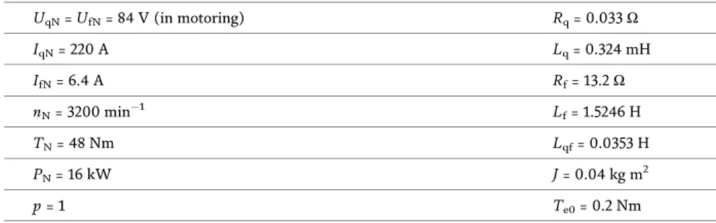
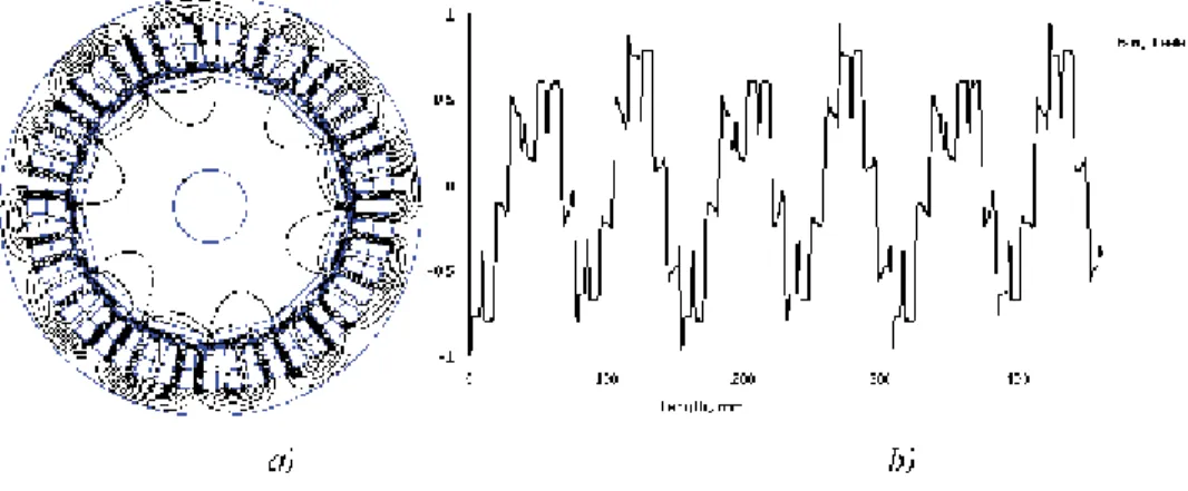
Output from the post processor, (a) distribution of the magnetic flux lines and (b) waveform of the magnetic flux density around the entire circumference of the air gap. The calculation of the air gap electromagnetic torque for the PMSM is made for the nominal condition based on the nameplate values.
Analysis of the switched reluctance motor parameters
- Calculation of the linkage magnetic flux
- Inductance of single-phase calculation
- Coenergy calculation
- Static electromagnetic torque of the SRM
Setting the current density of the fed phase (calculated based on the number of turns and phase current). It is given by the fact that the B-H curves of the sheets and the ferromagnetic axis are similar.
Symbols
Appendix
- Simulation model of separately excited DC motor in MATLAB-Simulink
- Simulation model of separately excited DC generator in MATLAB-Simulink
- Simulation model of shunt wound DC motor in MATLAB-Simulink
- Simulation model of shunt wound DC generator in MATLAB-Simulink
- Simulation model of DC series motor in MATLAB-Simulink
- Simulation model of DC series generator in MATLAB-Simulink
Appendix
- Simulation model of squirrel-cage motor in MATLAB-Simulink—
Detail of the model block of induction machine in MATLAB-Simulink
Simulation model of squirrel-cage motor in MATLAB-Simulink—
Simulation model of squirrel-cage motor in MATLAB-Simulink—
Simulation model of wound rotor asynchronous motor in MATLAB- Simulink — starting up by means of rheostat added to rotor circuit
Appendix
- Simulation model of synchronous motor with field winding in MATLAB-Simulink — starting up by means of frequency converter
- Detail of the model block of synchronous motor with field winding in MATLAB-Simulink
- Simulation model of synchronous motor with PM in MATLAB- Simulink — starting up by means of frequency converter
- Detail of the model block of synchronous motor with PM in MATLAB-Simulink
Appendix
- Lua-Script of FEM program for computing of SRM static parameters
This chapter is distributed under the terms of the Creative Commons Attribution License (http://creativecommons.org/licenses/.by/3.0), which permits unrestricted use, distribution, and reproduction in any medium, provided that the original work is properly cited . .