At the same time, hardness measurement, including the measurement of the hardness of a thin film, was also a research topic. In this way, the effect of the base material on the hardness (and on the measurement) will be less than 2% [4–8].
Methods
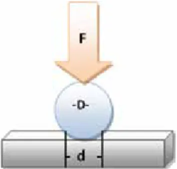
- Brinell's hardness test
- Rockwell's hardness test
- Vickers hardness test
- Microhardness test
The area (A) formed on the surface of the material is negatively proportional to the hardness of the material. The calculations are made by measuring the diagonals of the notch on the surface of the material.
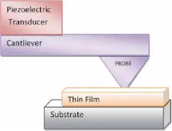
Hardness of thin films
Number of crystalline lines per unit area and dislocation density of the films versus deposition time [24]. Deposition time (min.) Number of crystalline lines per surface unit (1/nm2) Roughness (nm) Hardness (kg/mm2). a) Some parameters of the thin film according to hardness [24].
![Figure 6. X‐ray patterns of Mn 2 V 2 O 7 films with different deposition time: (a) 10 min, (b) 20 min, (c) 30 min, and (d) 40 min [24].](https://thumb-ap.123doks.com/thumbv2/1libvncom/9201179.0/16.765.310.457.231.748/figure-ray-patterns-mn-films-different-deposition-time.webp)
Elasticity module of thin films
Therefore, the elasticity of a flexible thin film is negatively correlated with average grain size, film thickness and surface roughness, while it is positively correlated with the number of crystalline lines per unit area. On the other hand, since most of the flexible thin films are polymer or organic composites, it is quite difficult to obtain the crystalline structure of these films.
Tensile and yield strength
The tensile strength and yield strength of thin films are among the characteristics that cannot be directly measured. As can be seen from these formulas, tensile strength and yield strength are negatively correlated with film thickness, average grain size, and surface roughness (in other words, the tensile strength and yield strength of a thin film decrease as these parameters increase), while they are positively correlated with the number of crystals per unit area (in other words, the tensile strength and yield strength increase as the number of particles per unit area increases).
The relationship between temperature and hardness
25] stated that they were able to calculate tensile and yield strengths with less than 2% error using these formulas. The only reason we don't use these formulas is that we haven't measured the hardness of Manganese.
Sensitivity coefficient
While measuring the hardness of a material, many parameters such as force, diameter, depth, time, etc.
Conclusion
Author details
Introduction
It also adversely affects the infrastructure (e.g. beaches), underwater ecosystem (fauna and flora) and adversely affects the economies in terms of losses in tourism, fishing, seafood sectors and expenses for their restoration [23–31]. In particular, adsorption practices are the single most promising alternatives in the isolation of metal ions that are otherwise very difficult to remove by means of photocatalysis and membrane filtration [57,58].
Adsorption
- Freundlich adsorption isotherm
- Langmuir adsorption isotherm
- Temkin adsorption isotherm
- Thermodynamic treatment of adsorption isotherm
- Kinetics of adsorption
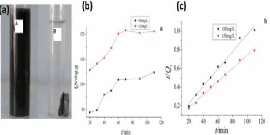
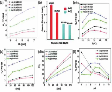
According to the Temkin adsorption isotherm, the adsorption energy is a linear function of the adsorbent surface coverage assuming indirect interaction of the adsorbent and adsorbate [18]. For a better look at the mechanical pathways, the three basic steps by which adsorption proceeds ie. i) movement of adsorbate particles through the bulk solution on the outer surface of the adsorbent, (ii) diffusion of adsorbate particles into the pores of the adsorbent (interparticle diffusion) and (iii) adsorption of adsorbate particles to the active sites of the adsorbent.
Absorption
If diffusion between particles is the rate-determining step of the adsorption process, then the above equation gives a straight line for qt versus t1/2 plots. If diffusion between particles is the rate-determining step of the adsorption process, then the above equation gives a straight line for qt versus t1/2 plots.
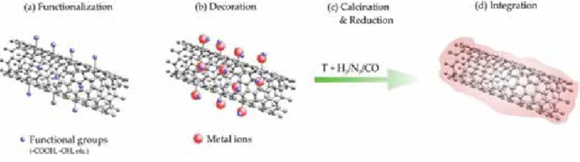
Synthesis of graphene-based hybrids and composites
- Dip-coating process
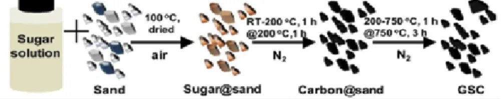
- Surface coating by in situ generation of graphene via thermal treatment
- In situ incorporation process
- Hydrothermal process in the presence of gelation-causing agent
Schematic representation of the in situ recording process where GO is mixed with suitable filler. This involves the hydrothermal treatment of GO dispersion in the presence of a suitable gelling agent, e.g. chitosan, leading to the formation of hydrogel [107], which can be lyophilized or supercritically dried to form the corresponding hybrid airgel.
The water purification performance of graphene-based hybrids and composites
- Adsorption of metal ions
- Adsorption of dyes
- Absorption of oils/organic solvents
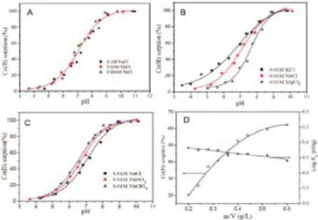
The Langmuir isotherm parameters of the Ni (II) adsorption on GNS-MnO2 composite at different temperatures (K). The authors also studied the role of dye solution pH (Figure 17b) on the adsorption mechanism of the composite.
Conclusion
Graphene oxide-hydrated zirconia nanocomposites for simultaneous removal of As(III) and As(V) from water. Cost effective graphene oxide coated polyurethane sponge as a highly efficient and reusable oil absorbent. Introducing an improved binding of reduced graphene oxide to polyurethane sponge for oil absorption.
The Application of Nanodiamond in Biotechnology and Tissue Engineering
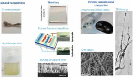
- Diamond nanoparticles
- Controlled drug and gene delivery
- Bioimaging
- Biosensing
- The potential cytotoxicity of diamond nanoparticles
- Nanostructured diamond films
- Diamond films as substrates for cell adhesion and growth
- Diamond films as substrates for biosensing and localized drug delivery
- Polymer-nanodiamond composites
- Conclusion
Nanodiamond-based drug delivery has been developed specifically for advanced tumor therapies, eg, the treatment of multidrug-resistant leukemia. The positive effects of NCD films on cell performance can be explained by their nanostructure, i.e., the presence of irregularities at the nanoscale level on their surface (eg, an average roughness parameter Ra equal to or less than 100 nm). Cell performance in nanodiamond films can be modulated by their roughness and topography, e.g., the size and shape of surface irregularities, ending with different atoms (e.g., O and H), chemical functional groups and biomolecules, and by boron doping.
Acknowledgements
DOI: 10.1080/03091900500217489
Enhanced growth and osteogenic differentiation of human osteoblast-like cells on boron-doped nanocrystalline diamond thin films. The effect of ultra-nanocrystalline diamond films on the proliferation and differentiation of neural stem cells. The surface properties of nanocrystalline diamond and nanoparticulate diamond powder and their suitability as supporting surfaces for cell growth.
Laser- Assisted Machining of Difficult to Cut Materials
Experiments
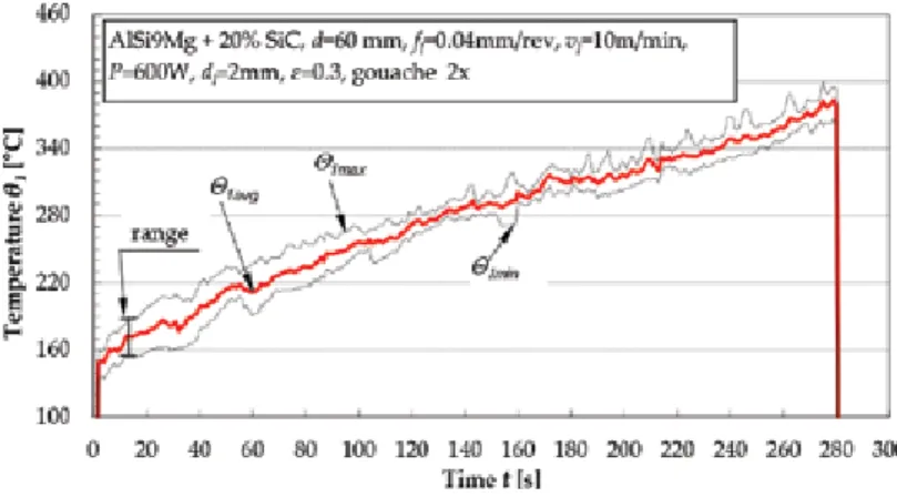
Laser-assisted machining (LAM) has recently emerged as a possible technique for achieving high material removal rates. This paper describes the experimental setup and characterization of the LAM process of Si3N4 ceramics, cemented carbide layers and metal matrix composites with special emphasis on diamond tool wear and surface roughness. Schematic of the experimental setup. a) MMC laser turning, (b) Ceramic turning with LAM, designa‐. tions: A—laser beam heating area, B—processing area, d—workpiece diameter, dl—laser beam diameter [1].
Results
- Laser surface heating
- Tool wear
- Machined surface roughness
Polycrystalline diamond (PCD) cuts wear as a function of the machined surface temperature after 1 tool pass. The average width of the profile roughness grooves (RSm) in the studied area is higher than the feed values (Figure 17). The machined surface roughness is one of the most important quality indicators for the MMC materials.
Conclusions
The studies on laser-assisted turning of difficult-to-cut materials confirmed that laser heating of the machined surface causes significant improvement in the turning process, which is estimated using tool wear and surface roughness indicators. Evaluation of surface roughness in laser-assisted machining of alumina ceramics using the Taguchi method. Multi-scale modeling to predict subsurface damage applied to laser-assisted machining of a particle-reinforced metal matrix composite.
DLC Thin Films and Carbon Nanocomposite Growth by Thermionic Vacuum Arc (TVA) Technology
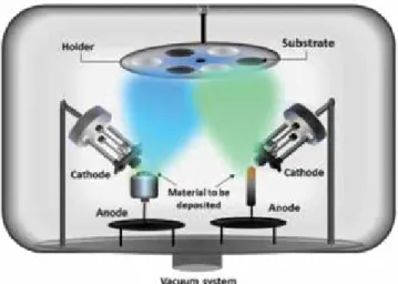
Basic principle of TVA method and experimental setup
The electric arc is ignited between the cathode and the carbon or metal anode material continuously vaporized by electrons accelerated at high voltage and incident on the anode. Vapor generation is achieved by electron bombardment of the anode material (eg carbon or metal) with electrons emitted from the filament and accelerated between the electrodes. The thin film is growing under the bombardment of the incident energetic ions, in addition to the neutral atoms of the material to be deposited from the anode.
DLC thin films
The originality of the TVA method consists in the fact that the energy introduced into the system for ignition of the plasma is provided simultaneously by an electron gun and a high-voltage source. Considering the discharge is carried out in vacuum conditions, one of the major advantages of this is. Therefore, for typical anode currents of 1 A, a potential difference equal to the cathode drop will accelerate the ions towards the walls of the vacuum vessel to energies of 500 eV.
Binary composites deposited by TVA technology
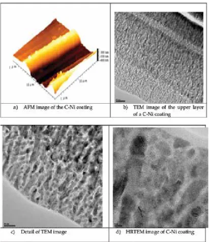
The surface morphology analyzed using an AFM (Atomic Force Microscope) in touch mode also shows a significant coating roughness. The high-resolution transmission electron microscope (HRTEM) image of the grains in the upper layer is shown in Figure 4d. Crystalline structure can be seen in most of the grains, while the surrounding matrix is amorphous.
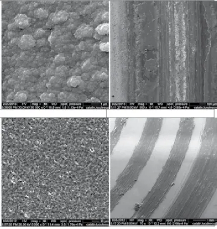
Ternary composites deposited by TVA technology
SEM image of C-Si-Al film deposited on silicon substrate (left) and coating image (right). TEM images (left) with particle selection for statistical determination and grain size distribution (right) of films deposited on different substrates. Comparative view of the substrate friction coefficient (OLC45) and the CSiAl film deposited on the sub-.
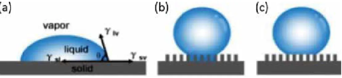
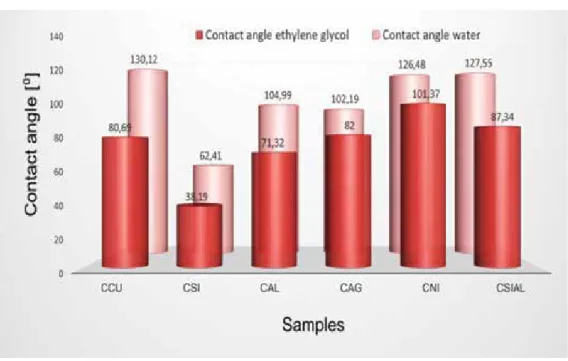
Surface-free energy properties for binary and ternary composites
In Figure 11, the angle of contact of the droplet with the solid surface is defined as "contact angle". 40] Vladoiu R, Ciupina V, Surdu-Bob C, Lungu CP: Properties of the carbon thin films deposited by thermionic vacuum arc. 42] Vladoiu R, Ciupina V, Dinca V, Musa G: Influence of the operational parameters on the wettability of the DLC films deposited by the TVA method.
Composites: Manufacturing and Evaluation
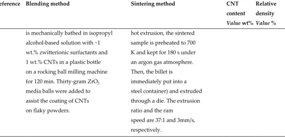
Blending methods
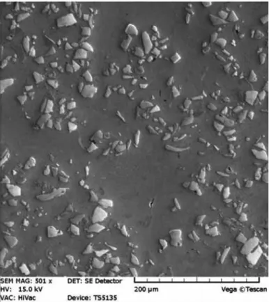
During the rotational motion, the added balls fall on top of the powder material (Figure 1b), leading to a size reduction, particle welding and integration of CNTs into the matrix powder material (Figure 1c and d) generated by the impact energy. Usually a process control agent, e.g. ethanol, is added to prevent cold welding of the powder particles of the matrix material. Some studies functionalize the surface of the CNTs to obtain electrochemically stable dispersions, which works great, but affects the physical properties of CNTs, as already discussed for molecular level mixing.
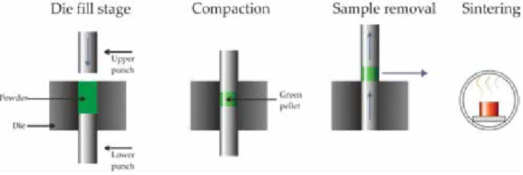
Processing methods
Sample heating is usually done by induction, so this system is very limited in heating speed, making HUP a very time-consuming sintering process. A pulsed electric direct current is applied, causing the sample to heat up through its electrical resistance. In contrast to HUP, the applied pressure during sintering is much lower (typically around 50 MPa) due to the mechanically weak graphite impacts.
Potential applications
This is because most of the literature is devoted to the study of the mechanical properties of composites. There, the measured yield stress improvement of different systems is given as a function of the CNT volume concentration in the composite. In this regard, some parts of the research in Cu-CNT were aimed at improving the thermal properties.
![Figure 7. Yield strength improvement against the volume fraction of CNTs in (a) Al/CNT composites [18,20,56,57,60]](https://thumb-ap.123doks.com/thumbv2/1libvncom/9201179.0/142.765.169.596.116.761/figure-yield-strength-improvement-volume-fraction-cnts-composites.webp)
Aluminium/CNT system
- Solid-state processing
- Distribution and interaction with the matrix material
A detailed review of research articles on the production of Al/CNT composites can be found in Table 1. Interestingly, it would be hypothesized that cluster formation would be detrimental to the proper densification of the composites. Both approaches are valid in the sense that they show a good overview of the agglomeration.
Copper/CNT system
- Solid-state processing
- Distribution and interaction with the matrix material
Ball milling: Cu powder and CNTs are mixed through high energy ball milling for 24 h at 150 rpm. The coated CNTs are dispersed in ethanol with vigorous sonication for 10 minutes, after which the copper powder is added. Colloid mixing process: CNTs are sonicated in ethanol for 1 h and stirred for 5 min using a magnetic stirrer.
Nickel/CNT system
- Solid-state processing
- Distribution and interaction with the matrix material
Aggregation of the dispersion of the CNTs in an ultrasonic bath with N,N-dimethylpyr mamide (DMF) and the subsequent addition of Ni powder. Aggregation of the dispersion of the CNTs in an ultrasound bath with ethylene glycol and the subsequent addition of Ni powder. A homogenizer (5-min treatment) combined with an ultrasonic bath (20-min treatment) is used for the dispersion of the CNTs.
Outlook
Role of interfacial oxygen atoms in improved mechanical properties of carbon nanotube reinforced metal matrix nanocomposites. Combination of hot extrusion and plasma spark sintering to produce aluminum matrix composites reinforced with carbon nanotubes. Effect of metal particle size and shape on the improvement of hardness and electrical properties of carbon nanotube-reinforced copper and copper alloy composites.
![Table 3. Some parameters of the thin film according to deposition time [24].](https://thumb-ap.123doks.com/thumbv2/1libvncom/9201179.0/17.765.90.681.817.935/table-parameters-film-according-deposition-time.webp)
![Figure 8. Number of crystalline per unit area and dislocation density of the films versus deposition time [24].](https://thumb-ap.123doks.com/thumbv2/1libvncom/9201179.0/18.765.99.673.289.760/figure-number-crystalline-dislocation-density-films-versus-deposition.webp)
![Figure 10. Relation between film thickness, average grain size, and hardness [24].](https://thumb-ap.123doks.com/thumbv2/1libvncom/9201179.0/19.765.168.599.121.390/figure-relation-film-thickness-average-grain-size-hardness.webp)
![Figure 11. Relation between number of crystalline per unit area, roughness, and hardness [24].](https://thumb-ap.123doks.com/thumbv2/1libvncom/9201179.0/19.765.157.610.461.748/figure-relation-number-crystalline-unit-area-roughness-hardness.webp)
![Table 5. (a) Some parameters of the thin film according to hardness [24].](https://thumb-ap.123doks.com/thumbv2/1libvncom/9201179.0/19.765.89.681.816.934/table-parameters-film-according-hardness.webp)
![Table 6 shows the list prepared by Ludvik [28], showing the hardness the thin films pro‐](https://thumb-ap.123doks.com/thumbv2/1libvncom/9201179.0/23.765.91.676.596.937/table-shows-list-prepared-ludvik-showing-hardness-films.webp)
![Figure 7. Photograph of GO/chitosan hydrogel and its SEM image. Reproduced from [107] with the permission from RSC.](https://thumb-ap.123doks.com/thumbv2/1libvncom/9201179.0/38.765.136.634.684.907/figure-photograph-chitosan-hydrogel-sem-image-reproduced-permission.webp)