Journal Pre-proofs
Free vibration and buckling of bidirectional functionally graded sandwich beams using an enriched third-order shear deformation beam element Cong Ich Le, Ngoc Anh T. Le, Dinh Kien Nguyen
PII: S0263-8223(20)33235-9
DOI: https://doi.org/10.1016/j.compstruct.2020.113309
Reference: COST 113309
To appear in: Composite Structures Received Date: 22 July 2020
Accepted Date: 7 November 2020
Please cite this article as: Le, C.I., T. Le, N.A., Nguyen, D.K., Free vibration and buckling of bidirectional functionally graded sandwich beams using an enriched third-order shear deformation beam element, Composite Structures (2020), doi: https://doi.org/10.1016/j.compstruct.2020.113309
This is a PDF file of an article that has undergone enhancements after acceptance, such as the addition of a cover page and metadata, and formatting for readability, but it is not yet the definitive version of record. This version will undergo additional copyediting, typesetting and review before it is published in its final form, but we are providing this version to give early visibility of the article. Please note that, during the production process, errors may be discovered which could affect the content, and all legal disclaimers that apply to the journal pertain.
© 2020 Published by Elsevier Ltd.
Free vibration and buckling of bidirectional functionally graded sandwich beams using an enriched third-order
shear deformation beam element
Cong Ich Le1, Ngoc Anh T. Le2,3, Dinh Kien Nguyen3,4∗
1Le Quy Don Technical University, 236 Hoang Quoc Viet, Hanoi, Vietnam
2Institute of Applied Mechanics and Informatics, VAST, 291 Dien Bien Phu, Ho Chi Minh city, Vietnam
3Graduate University of Science and Technology, VAST, 18 Hoang Quoc Viet, Hanoi, Vietnam
4Institute of Mechanics, VAST, 18 Hoang Quoc Viet, Hanoi, Vietnam
Abstract
This paper formulates an efficient third-order shear deformation beam element for free vibration and buckling analysis of bidirectional functionally graded sand- wich (BFGSW) beams. The beams consist of three layers, an axially functionally graded core and two face sheets with material properties varying in both the thick- ness and length directions by power-law distributions. The element is derivedin this paper for the first timeby using hierarchical functions to enrich the Lagrange and Hermite interpolations of a conventional beam element, and this enrichment results in a super convergent beam element. Using the formulated beam element, natural frequencies and buckling loads are evaluated for the beams with various boundary conditions. The effects of the material distribution and the layer thick- ness on the vibration and buckling characteristics are examined in detail and high- lighted. The influence of the micromechanical models, namely the Voigt model and Mori-Tanaka scheme used in estimating the effective material properties, on the vibration frequencies and buckling loads of the beams is also examined and discussed.
Key words: BFGSW beam; third-order shear deformation theory; vibration and buckling analysis; hierarchic enrichment; beam element.
∗Corresponding author (D.K. Nguyen), Tel.: +84-24-37628006; fax: +84-24-37622039.
E-mail address: [email protected]
0DQXVFULSW)LOH &OLFNKHUHWRYLHZOLQNHG5HIHUHQFHV
1. Introduction
Beam as a major part in many structures can be designed to have better perfor- mance by using functionally graded materials (FGMs), a new type of composite initiated by Japanese researchers in 1984 [1]. Mechanical characteristics of the beam are significantly altered by material variation in the length or thickness di- rection. Analysis of beams made of FGMs has been extensively carried out in the last few decades, by using both analytical and numerical methods. The fi- nite element method with its simplicity and versatility in the spatial discretization is an effective toll in analyzing inhomogeneous structures, especially when the nonlinearities are involved [2, 3]. Regarding the finite element analysis of FGM beams, the topic discussed herein, Kadoli et al. [4] derived a third-order shear deformation beam element for static analysis of ceramic-metal beams with ma- terial properties varying in the thickness direction by a power law. Shahba et al. [5] presented a first-order shear deformation finite element formulation for vibration and buckling analysis of tapered axially FGM beams. The formulation using the quadratic and cubic polynomials to interpolate the rotation and trans- verse displacement, respectively, is free of shear locking. Alshorbagy et al. [6], Eltaher et al. [7, 8] studied free vibration of FGM beams using the traditional Euler-Bernoulli or Timoshenko beam elements. Taeprasartsit [9] employed the solution of the nonlinear equilibrium equations of a Timoshenko beam to inter- polate the displacement field in deriving a beam element for buckling analysis of FGM columns. The derived element is accurate and fast convergent. Nguyen [10, 11], Nguyen and Gan [12] formulated nonlinear beam elements for large dis- placement analysis of tapered beams. The material properties of the beams are considered to vary in the thickness or length direction. Based on the hierarchical displacement field, Filippi et al. [13] presented the finite elements for bending analysis of FGM beams. The stiffness and mass matrices for vibration analysis of FGM Euler-Bernoulli beams were derived by Jin and Wang [14] using the dif- ferential quadrature rule. Murin et al. [15] formulated a finite beam element for modal analysis of spatial FGM beams. The transversal and longitudinal variation of the material properties was taken into account in the element. Frikha et al.
[16] formulated aC1 beam element for bending study of FGM beams. The ele- ment with four degrees of freedom per node is derived using a mixed formulation.
Based on the first-order shear deformation beam theory, Kahya and Turan [17]
derived a five-node beam element for vibration and buckling analysis of FGM
beams. Lagrange functions were used to interpolate the displacement field.
With the advanced manufacturing methods [18, 19], FGMs can now be in- corporated into sandwich construction to improve performance of the structures.
FGM sandwich beams can be designed to have a smooth variation of the material properties, which helps to eliminate the delamination problems at the interfaces between layers. Investigations on mechanical behaviour of FGM sandwich beams are extensively reported in recent years [20]. Chakraborty et al. [21] studied bend- ing, free vibration and wave propagation of sandwich beams with a FGM core using a first-order shear deformation finite element formulation. The formula- tion employed solution of the static governing differential equations to interpolate the displacement field is free of the shear locking. Also using the finite element method, Bhangale and Ganesan [22] investigated thermal effects on bucking and vibration of FGM sandwich beams with a viscoelastic core. Using the modified differential quadrature method, Pradhan and Murmu [23] evaluated the effect of temperature rise on the natural frequencies of FGM sandwich beams. Various beam models were employed by Apetre et al. [24] to study bending behaviour of FGM sandwich beams under distributed loads. The effect of the beam model on the response of the beam was examined. Rahmani et al. [25] presented a high-order sandwich panel theory for free vibration analysis of sandwich beams with a flexible functionally graded syntactic core. Amirani et al. [26] studied free vibration of a sandwich beam with FG core using the element free Galerkin method. Zenkour et al. [27] investigated bending behaviour of a sandwich beam on a Pasternak foundation using various beam theories. The beam consists of an elastic core and two faces of viscoelastic FGM. The mesh free boundary-domain integral equation method was used by Yang et al. [28] in studying free vibration of FGM sandwich beams. Su et al. [29] employed the general Fourier formulation to calculate frequencies of FGM sandwich beams resting on a Pasternak foundation.
Both Voigt and Mori-Tanaka models were employed by the authors to estimate the effective properties of the beams. Vo et al. [30–32], Nguyen et al. [33–35], Ben- nai et al. [36] presented various shear deformation theories for vibration, buckling and bending analyses of FGSW beams. The transverse displacement in the the- ories is split into bending and shear parts or in-plane displacement is modified using hyperbolic functions. Vibration and buckling of sandwich beams with FGM faces were studied by Osofero et al. [37] using a quasi-3D theories. Trinh et al.
[38] calculated natural frequencies of FGM sandwich beams using the state space approach. Chebyshev collocation method was used by Tossapanon et al. [39]
to study vibration and buckling of FGM sandwich beams on elastic foundation.
The semi-analytical methods were used in [40, 41] to study dynamic behaviour of FGM sandwich beams under moving loads. Yarasca et al. [42] derive a beam element for studying bending of FGM sandwich beams. The element with seven degrees of freedom is derived using a quasi-3D beam theory.
Development of FGM structures with material properties varying in two or more directions to meet multi-functional requirements is demanding [43]. Anal- ysis of bidirectional FGM beams has been considered recently. L¨u et al. [44]
studied bending and thermal deformation of FGM beams with Young’s modulus varying in both the beam length and thickness by an exponential function. Also assuming an exponential variation for the material properties, S¸ims¸ek [45] studied vibration of a FGM beam excited by moving forces. The effect of longitudinal and transverse variation of material properties on free vibration of bidirectional FGM beams was examined by Hao and Wei [46], Wang et al. [47]. The NURBS iso- geometric finite element method was used in [48, 49] to study thermo-mechanical and vibration behaviour of bidirectional FGM beams, respectively. Nguyen et al.
[50], Nguyen and Tran [51] derived the finite element formulations for studying vibration of FGM beams with material properties varying in both the thickness and length directions by the power distribution laws. Also using the finite element method, Nguyen and Lee [52] studied flexural-torsion vibration and buckling of thin-wall FGM beams with material properties varying in both the thickness and longitudinal direction by various power gradation laws. An efficient numerical technique, in which the artificial neural network is integrated into the differential evolution method, was proposed by Truong et al. [53] for optimization of bidirec- tional FGM beams under free vibration. Bending analysis of bidirectional func- tionally graded sandwich (BFGSW) beams carried out by Karamanli [54] showed that the longitudinal variation of the material properties significantly influences on the behaviour of the beams.
The accuracy and efficiency of a finite element can be improved by enriching the conventional interpolation. Arndt et al. [55] showed that the convergence of a bar element for longitudinal free vibration analysis of bars and trusses can be significantly improved by using trigonometric functions to enrich the linear inter- polation. A Timoshenko beam element for free vibration analysis was derived by Hsu [56] using hierarchic functions to enrich the conventional linear interpolation.
The derived element is efficient and it is free of the shear locking. Hsu and Deitos [57] showed that the Euler-Bernoulli beam element derived by using trigonometric functions to enrich the linear and Hermite interpolation functions is more accurate and efficient in predicting dynamic response of frames to wind load. Motivated by
these works, an enriched beam element for free vibration and buckling analysis of BFGSW beams is formulated in this paper. The beams consist of three layers, an axially FGM core and two bidirectional FGM skin faces with material properties varying in both the thickness and length directions by power gradation laws. Two micromechanical models, namely the Voigt model and Mori-Tanaka scheme, are employed to evaluate the effective properties of the beams. The element based on a third-order shear deformation theory is derived by using hierarchical functions to enrich the conventional Lagrange and Hermite interpolations. The resulted el- ement is efficient, and it helps to improve computation in vibration and buckling analysis of BFGSW beams by the finite element method. Numerical investigation is carried out to show the efficiency of the enriched element, and to highlight the effects of the material distribution and the layer thickness ratio on the vibration and buckling characteristics of the beams.
2. BFGSW Beam
A BFGSW beam with lengthL, rectangular cross section(b×h)as depicted in Fig. 1 is considered. The beam consists of three layers, a FGM core and two bidirectional FGM skin layers. The Cartesian system (x,y,z) in Fig. 1 is chosen such that thex-axis is on the mid-plane, while thez-axis directs upward. Denoting z0, z1, z2andz3are, respectively, the vertical coordinates of the bottom surface, two interfaces between the layers, and the top surface.
The beam is made from a mixture of ceramic and metal. The volume fraction of ceramic(Vc)and metal(Vm)varies in both the thickness and length directions according to
Vc=
z−z0 z1−z0
nz 1− x
2L nx
, forz∈[z0, z1]
1− x 2L
nx
, forz∈[z1, z2]
z−z3
z2−z3 nz
1− x 2L
nx
, forz∈[z2, z3]
(1)
andVm=1−Vc. In Eq. (1),nx andnz are the non-negative axial and transverse power-law indexes, which determine the material distribution in the length and thickness directions of the beam, respectively. The beam model in (1) is modified slightly from that of Ref. [54] so that the conventional unidirectional FGM sand- wich beam, e.g. the sandwich beam in Refs. [29, 30], is a special case of (1) when
nx =0. Fig. 2 shows the distribution of Vc andVm in the xand z directions for z1=−h/4, z2=h/4 and two pairs of the power-law indexes, nx=nz =0.5 and nx=nz=5. The figure shows a smooth variation of theVcandVmin the thickness and length directions.
Two micromechanical models, namely Voigt model and Mori-Tanaka scheme, are employed herein to evaluate the effective material properties of the beam. An effective property (Pf) such as elastic modulus and mass density evaluated by the Voigt model is of the form
Pf = (Pc−Pm)Vc+Pm (2) wherePcandPmare the properties of the ceramic and metal, respectively.
According to Mori-Tanaka scheme [58], the effective bulk modulus Kf and shear modulusGf at any point of the beam are given by
Kf−Km
Kc−Km = Vc
1+Vm(Kc−Km)/(Km+4Gm/3) Gf−Gm
Gc−Gm = Vc
1+Vm(Gc−Gm)/[Gm+Gm(9Km+8Gm)/(6Km+12Gm)]
(3)
where
Kc= Ec
3(1−2νc),Gc= Ec
2(1+νc),Km= Em
3(1−2νm),Gm= Em
2(1+νm) (4) are the bulk and the shear moduli of the ceramic and metal, respectively.
The effective Young’s modulusEf and Poisson’s ratioνf are computed via the effective bulk modulus and shear modulus as
Ef = 9KfGf
3Kf+Gf , νf = 3Kf−2Gf
6Kf+2Gf (5)
Noting that the effective mass densityρf is defined by Voigt model according to Eq. (2).
3. Mathematical formulation
The refined third-order shear deformation theory in which the transverse dis- placement is split into bending and shear parts [59] is adopted herein. According
to the theory, the displacements of a point in x and z directions, u(x,z,t) and w(x,t), respectively, are given by
u(x,z,t) =u0(x,t)−zwb,x(x,t)− 5z3
3h2− z 4
ws,x(x,t) w(x,t) =wb(x,t) +ws(x,t)
(6)
where u0(x,t) is the axial displacement of a point on the x-axis; wb(x,t) and ws(x,t)are, respectively, the bending and shear components of the transverse dis- placement. A subscript comma in the above equation and hereafter is used to denote the derivative with respect to the variable that follows.
The strain components resulted from Eq. (6) are of the forms εx=u0,x−zwb,xx−f(z)ws,xx
γxz=g(z)ws,x
(7) where
f(z) = 5z3 3h2−z
4, g(z) =1−f,z(z) (8) Based on linear behaviour of the beam material, one can write the strain energy (U)of the beam in the form
U= 1 2
Z
V
Ef(x,z)[u0,x−zwb,xx−f(z)ws,xx]2+Gf(x,z)g2(z)w2s,x dV
= 1 2
Z L
0
u0,x wb,xx ws,xx
T
I1 −I2 −I3
−I2 I5 I4
−I3 I4 I6
u0,x wb,xx ws,xx
+ws,xI7ws,x
dx
(9)
where V is the beam volume, andI1, I2, ...I7are the beam rigidities, defined as (I1,I2,I3,I4,I5,I6) =b
Z h/2
−h/2Ef(x,z)[1,z,f(z),z f(z),z2,f2(z)]dz, I7=b
Z h/2
−h/2Gf(x,z)g2(z)dz
(10)
In Eq. (9) and hereafter a superscript ‘T’ denotes the transpose of a vector or a matrix.
The kinetic energy of the beam resulted from Eq. (6) is of the form T =1
2 Z
Vρf
[u˙0−zw˙b,x−f(z)w˙s,x]2+ (w˙b+w˙s)2 dV
=1 2
Z L 0
˙ u0
˙ wb,x
˙ ws,x
T
J1 −J2 −J3
−J2 J5 J4
−J3 J4 J6
˙ u0
˙ wb,x
˙ ws,x
+ w˙b
˙ ws
T J1 J1 J1 J1
˙ wb
˙ ws
dx
(11) where an over dot denotes the derivative with respect to the time variable t, and the mass momentsJ1, J2, ...J6are defined as
(J1,J2,J3,J4,J5,J6) =b Z h/2
−h/2ρf(x,z)
1,z,f(z),z f(z),z2,f2(z)
dz (12) Finally, the potential energy resulted by the axial forceP0is given by
V = 1 2
Z L 0
P0w2,xdx= 1 2
Z L 0
P0(wb,x+ws,x)2dx
= 1 2
Z L 0
wb,x ws,x
T P0 P0 P0 P0
wb,x ws,x
dx
(13)
withP0is negative for a compressive axial force.
4. Enriched beam element
A conventional two-node beam element with length of l can be formulated from the energy expressions derived in the previous section by using Lagrange and Hermite functions to interpolate the axial and transverse displacements, re- spectively, as [30]
u0=Ndu, wb=Hdb, ws=Hds (14) where
du={u01 u02}T, db={wb1 wb1,x wb2 wb2,x}T,
ds={ws1 ws1,x ws2 ws2,x}T (15) are the vectors of nodal displacements;N={N0 N1}, H={H0 H1 H2 H3}are, respectively, the matrices of the following Lagrange and Hermite polynomials
N0=1−ξ
2 , N1= 1+ξ
2 (16)
and
H0=1 2−3
4ξ+1
4ξ3, H1= l
8(1−ξ−ξ2+ξ3) H2=1
2+3 4ξ−1
4ξ3, H3= l
8(−1−ξ+ξ2+ξ3)
(17) withξ=2x/l−1 is the natural coordinate. In substituting Eqs. (14)-(17) into Eqs.
(9), (11) and (13), one can obtain the conventional stiffness, mass and geometric matrices for vibration and buckling analysis, respectively.
In order to improve the convergence of the element, the above interpolation is enriched herein by adding higher-order functions to the original Lagrange and Hermite functions. In the present work, the Lagrange and Hermite interpolations are enriched by adding four higher-order hierarchic functions. In this regard, the interpolation (14) is now replaced by
u0=Ndu+Nˆ5dˆu, wb=Hdb+Hˆ7dˆb, ws=Hdb+Hˆ7dˆs (18) where ˆN5={N2 N3 ...N5}and ˆH7={H4 H5 ...H7}are the added matrices of the fifth and seventh-order interpolation functions, respectively; ˆdu, ˆdb, ˆds are the added vectors of unknowns with the following forms
dˆu={a1 a2 a3 a4}T, dˆb={ab1 ab2 ab3 ab4}T,
dˆs={as1 as2 as3 as4}T
(19) witha1...a4,ab1...ab4andas1...as4are the additional degrees of freedom.
The hierarchic functionsNp+1(p=1..4)andHk+1(k=3..6)in Eq. (18) can be generated along the element without introducing nodes, but can instead use parameters without obvious meaning [60]. According to [61],Np+1andHk+1are defined as follows
Np+1= Z ξ
−1Lp(ζ)dζ, Hk+1= Z ξ
−1Nk(ζ)dζ (20) withLpare the normalized Legendre polynomials,kLpkL2(−1,1)=1 for allp≥0.
The following functions obtained from the orthogonality and symmetry re- quirements are used in the present work [61]
N2(ξ) =1 2
r3
2(ξ2−1), N3(ξ) = 1 2
r5
2(ξ2−1)ξ N4(ξ) =1
8 r7
2(ξ2−1)(5ξ2−1), N5(ξ) =1 8
r9
2(ξ2−1)(7ξ2−3)ξ
(21)
and
H4(ξ) = r 5
128(1−ξ2)2, H5(ξ) = r 7
128(1−ξ2)2ξ, H6(ξ) =1
6 r 9
128(1−ξ2)2(−7ξ2+1), H7(ξ) =1
2 r 11
128(1−ξ2)2(3ξ2−1)ξ
(22)
Using the above interpolations, one can write the strain energy of the beam in Eq. (9) in the form
U= 1 2
NE
∑
dTekede (23) wherede
22×1={du dˆu db dˆb ds dˆs}T (24) is the vector of the degrees of freedom for the element, and ke is the element stiffness matrix, which can be written in sub-matrices as
ke
22×22=
kuu kuuˆ kub kubˆ kus kuˆs kTuuˆ kuˆuˆ kubˆ kuˆbˆ kusˆ kuˆˆs kTub kTubˆ kbb kbbˆ kbs kbˆs kT
ubˆ kT
ˆ ubˆ kT
bbˆ kbˆbˆ kbsˆ kbˆˆs kTus kTusˆ kTbs kTˆ
bs kss kssˆ kTuˆs kTuˆˆs kTbˆs kTˆ
bˆs kTssˆ ksˆsˆ
(25)
The summation in (23) is taken over the total number of the element,NE.
Noting that∂(.)/∂x= 2l∂(.)/∂ ξ anddx= 2ldξ, one can obtain the expres- sions for the sub-matrices as follows
kuu
2×2= 2 l
Z 1
−1NT,ξI1N,ξdξ, kuˆuˆ
4×4= 2 l
Z 1
−1
NˆT5,ξI1Nˆ5,ξdξ, kbb
4×4= 8 l3
Z 1
−1HT,ξ ξI5H,ξ ξdξ, kbˆbˆ
4×4
= 8 l3
Z 1
−1
HˆT7,ξ ξI5Hˆ7,ξ ξdξ, kss
4×4= Z 1
−1
8
l3HT,ξ ξI6H,ξ ξ+2
lHT,ξI7H,ξ
dξ
ksˆˆs
4×4= Z 1
−1
8 l3
HˆT7,ξ ξI6Hˆ7,ξ ξ+2 l
HˆT7,ξI7Hˆ7,ξ
dξ
(26)
and the coupling terms are kuuˆ
2×4= 2 l
Z 1
−1NT,ξI1Nˆ5,ξdξ, kub
2×4=−4 l2
Z 1
−1NT,ξI2H,ξ ξdξ, kubˆ
2×4
=−4 l2
Z 1
−1
NT,ξI2Hˆ7,ξ ξdξ, kus
2×4=−4 l2
Z 1
−1
NT,ξI3H,ξ ξdξ,
kuˆs
2×4
=−4 l2
Z 1
−1
NT,ξI3Hˆ7,ξ ξdξ, kubˆ
4×4
=−4 l2
Z 1
−1
NˆT5,ξI2H,ξ ξdξ, kuˆbˆ
4×4
=−4 l2
Z 1
−1
NˆT5,ξI2Hˆ7,ξ ξdξ, kusˆ
4×4=−4 l2
Z 1
−1
NˆT5,ξI3H,ξ ξdξ, kuˆˆs
4×4=−4 l2
Z 1
−1
NˆT5,ξI3Hˆ7,ξ ξdξ, kbbˆ
4×4
= 8 l3
Z 1
−1HT,ξ ξI5Hˆ7,ξ ξdξ, kbs
4×4
= 8 l3
Z 1
−1
HT,ξ ξI4H,ξ ξdξ, kbˆs
4×4
= 8 l3
Z 1
−1
HT,ξ ξI4Hˆ7,ξ ξdξ kbsˆ
4×4
= 8 l3
Z 1
−1
HˆT7,ξ ξI4H,ξ ξdξ kbˆsˆ
4×4
= 8 l3
Z 1
−1
HˆT7,ξ ξI4Hˆ7,ξ ξdξ kssˆ
4×4= Z 1
−1
8
l3HT,ξ ξI6Hˆ7,ξ ξ+2
lHT,ξI7Hˆ7,ξ
dξ
(27)
The kinetic energy of the beamT in Eq. (11) can also be written in the form T = 1
2
NE
∑
d˙Temed˙e (28) wheremeis the element mass matrix which can be written in sub-matrices asme
22×22=
muu muuˆ mub mubˆ mus muˆs mTuuˆ muˆuˆ mubˆ muˆbˆ musˆ muˆˆs mTub mTubˆ mbb mbbˆ mbs mbˆs mT
ubˆ mT
ˆ ubˆ mT
bbˆ mbˆbˆ mbsˆ mbˆˆs mTus mTusˆ mTbs mTˆ
bs mss mssˆ mTuˆs mTuˆˆs mTbˆs mTˆ
bˆs mTssˆ msˆsˆ
(29)
The expressions for the sub-matrices in (29) are as follows muu
2×2 =l 2
Z 1
−1NTJ1Ndξ, muˆuˆ
4×4 = l 2
Z 1
−1
NˆT5J1Nˆ5dξ, mbb
4×4
= Z 1
−1
l
2HTJ1H+2
lHT,ξJ5H,ξ
dξ,
mbˆbˆ
4×4
= Z 1
−1
l 2
HˆT7J1Hˆ7+2 l
HˆT7,ξJ5Hˆ7,ξ
dξ,
mss
4×4= Z 1
−1
l
2HTJ1H+2
lHT,ξJ6H,ξ
dξ
msˆsˆ
4×4= Z 1
−1
l
2HˆT7J1Hˆ7+2
lHˆT7,ξJ6Hˆ7,ξ
dξ
(30)
and muuˆ
2×4
=l 2
Z 1
−1
NTJ1Nˆ5dξ, mub
2×4
=− Z 1
−1
NTJ2H,ξdξ
mubˆ
2×4
=− Z 1
−1NTJ2Hˆ7,ξdξ, mus
2×4 =− Z 1
−1NTJ3H,ξdξ, musˆ
2×4 =− Z 1
−1NTJ3Hˆ7,ξdξ, mubˆ
4×4
=− Z 1
−1
NˆT5J2H,ξdξ, muˆbˆ
4×4
=− Z 1
−1
NˆT5J2Hˆ7,ξdξ, musˆ
4×4
=− Z 1
−1
NˆT5J3H,ξdξ, muˆsˆ
4×4 =− Z 1
−1
NˆT5J3Hˆ7,ξdξ, mbbˆ
4×4
= Z 1
−1
l
2HTJ1Hˆ7+2
lHT,ξJ5Hˆ7,ξ
dξ,
mbs
4×4 = Z 1
−1
l
2HTJ1H+2
lHT,ξJ4H,ξ
dξ,
mbsˆ
4×4
= Z 1
−1
l
2HTJ1Hˆ7+2
lHT,ξJ4Hˆ7,ξ
dξ,
mbsˆ
4×4
= Z 1
−1
l
2HˆT7J1H+2
lHˆT7,ξJ4H,ξ
dξ,
mbˆsˆ
4×4
= Z 1
−1
l
2HˆT7J1Hˆ7+2
lHˆT7,ξJ4Hˆ7,ξ
dξ
mssˆ
4×4= Z 1
−1
l
2HTJ1Hˆ7+2
lHT,ξJ6Hˆ7,ξ
dξ
(31)
The potential energyV in Eq. (13) is now of the form V =1
2
NE
∑
dTekGede (32) withkGe is the element geometric stiffness matrix with the following formskGe
22×22
=
0 0 0 0 0
0 kGbb kG
bbˆ kGbs kGbsˆ 0 (kG
bbˆ)T kGˆ
bbˆ kGˆ
bs kGˆ
bsˆ
0 (kGbs)T (kGˆ
bs)T kGss kGssˆ 0 (kGbsˆ)T (kGˆ
bˆs)T (kGssˆ)T kGsˆsˆ
(33)
where kGbb, kG
bbˆ, kGˆ
bbˆ, kGss, kGsˆsˆ, kGssˆ, kGbs, kGˆ
bs, kGbˆs and kGˆ
bsˆ are, respectively, the ge- ometric matrices stemming from the bending, shear and their coupling with the following forms
kGbb
4×4
=kGbs=kGss= 2 l
Z 1
−1HT,ξP0H,ξdξ kG
bbˆ 4×4
=kGbsˆ=kGssˆ= 2 l
Z 1
−1HT,ξP0Hˆ7,ξdξ kGˆ
4×4bs
= 2 l
Z 1
−1
HˆT7,ξP0H,ξdξ kGˆ
bbˆ 4×4
=kGˆ
bsˆ=kGsˆsˆ= 2 l
Z 1
−1
HˆT7,ξP0Hˆ7,ξdξ
(34)
Gauss quadrature with 6 points along the element length is used to evaluate the integrals in (26), (27), (30), (31) and (34). More points have been used, but no improvement in the numerical results was seen.
Equations of motion for the beam in the context of finite element analysis can be obtained from the Hamilton’s principle
δ Z t2
t1
(T −U−V)dt =0 (35)
Assuming a harmonic form for the vector of nodal displacements, the Hamil- ton’s principle leads to discrete equation of motion in the form
(K−PcrKG−ω2M)D¯ =0 (36)
where M, K and KG are, respectively, the global mass matrix, stiffness matrix and geometric stiffness matrix; Pcr, ω and ¯D are the critical buckling load, the frequency and the eigenvector of nodal displacements corresponding to an eigen- value, respectively.
5. Numerical investigation
Numerical investigation is carried out in this section to show the efficiency of the derived beam element and to illustrate the effects of various parameters on the vibration and buckling behaviour of the BFGSW beams. Otherwise stated, a BFGSW beam made from aluminum (Al) and alumina(Al2O3)with the following material properties [29, 30] is employed herewith
• Em= 70 GPa,ρm= 2702 kg/m3,νm= 0.3 for aluminum
• Ec= 380 GPa,ρc= 3960 kg/m3,νc= 0.3 for alumina
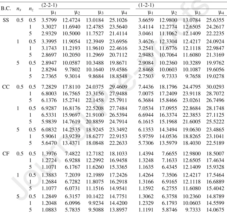
The following non-dimensional parameters are used for natural frequencies and buckling load [29]
µi= ωiL2 h
rρm
Em, Pcr∗ =Pcr
12L2
Emh3 (37)
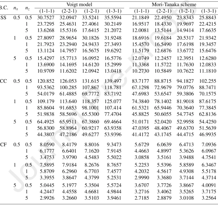
whereωiis the ith natural frequency, and Pcr ´ı the buckling load. Three number in brackets are used below to denote the layer thickness ratio, e.g. (1-2-1) means that the thickness ratio of the bottom layer, the core layer and the top layer is 1:2:1. Three types of boundary conditions (B.C.), namely simply-supported (SS), clamped-clamped (CC) and clamped-free (CF), are considered.
5.1. Accuracy and convergence studies
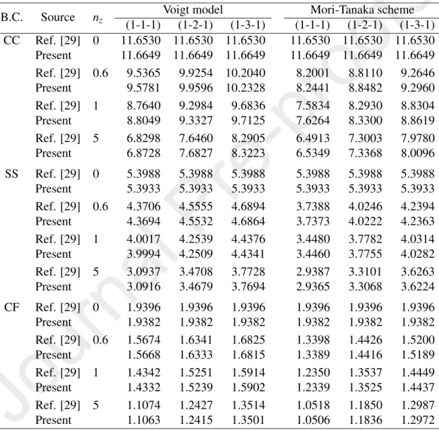
The accuracy of the derived beam element is carried out herewith by com- paring the fundamental frequencies and buckling loads of FGM sandwich beam for some special cases obtained herein with the published data. To this end, Ta- bles 1 compares the fundamental frequency parameter of a unidirectional FGM sandwich beam with L/h=10 as a special case of the present sandwich beam when nx =0, obtained in the present work with that of Su et al. [29] using a general Fourier formulation. The maximum relative error of the fundamental fre- quency parameter of the present work to that of Ref. [29] in Table 1, defined as Relative error (%)=|(µ1−µRef. [29])/µ1| ×100, is only 0.67, 0.10 and 0.12%
for the CC, SS and CF beams, respectively. Thus, regardless of the boundary
condition, the layer thickness ratio and the micromechanical model, a good agree- ment between the frequency parameters of the present work with that of Ref. [29]
is noted from Table 1.
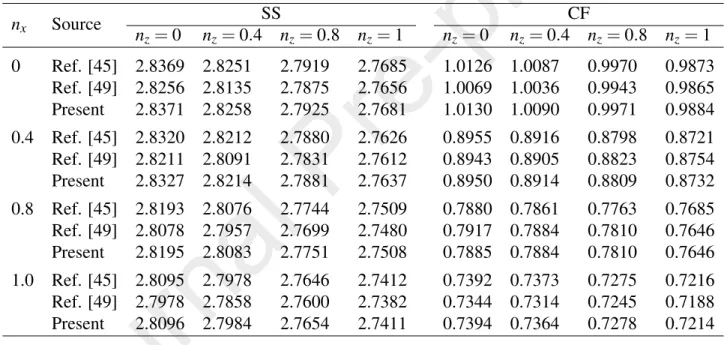
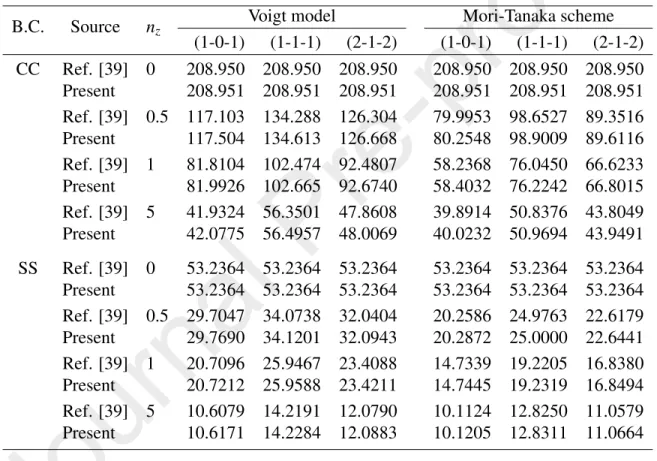
The fundamental frequency parameter of a BFGSW beam with material prop- erties varying exponentially in the thickness and longitudinal direction obtained in the present work is compared with the results based on the semi-analytical method of Ref. [45] and the NURBS-based numerical solution of Ref. [49]. A good agreement between frequency parameter of the present work with that of Refs. [45, 49] is seen from Table 2. It should be noted that since the beam model in Refs. [45, 49] is not a special case of the current beam, some formulations must be reformulated in computing the frequency parameter in Table 2. The buckling loads obtained in the present work, as shown in Table 3, are also in good agree- ment with the result of Ref. [39], in which the Chebyshev collocation method has been used.
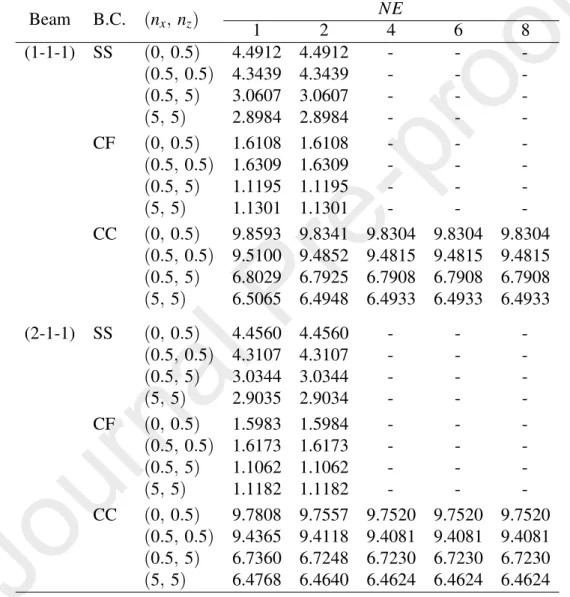
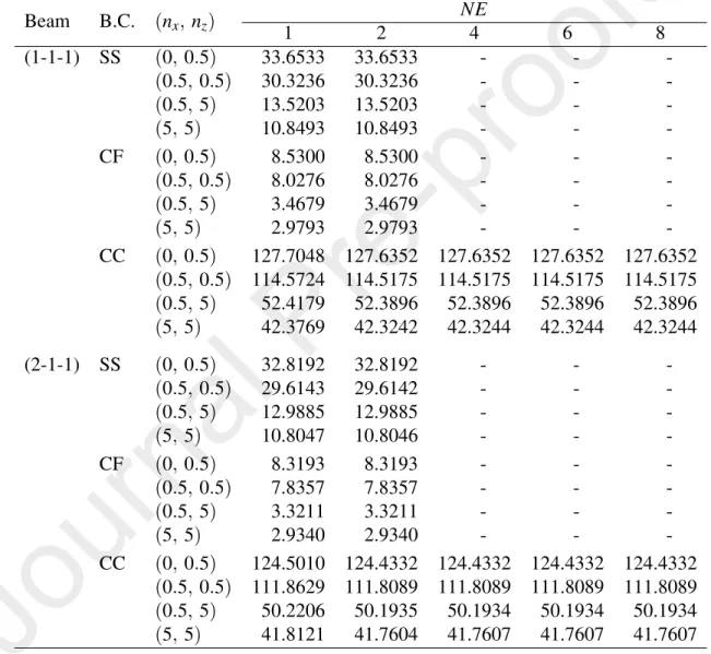
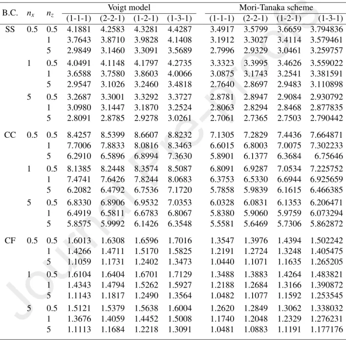
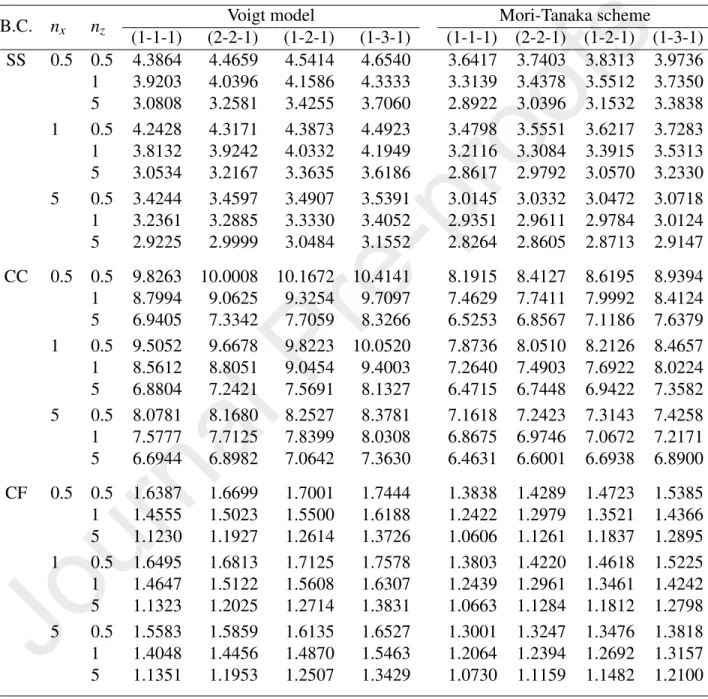
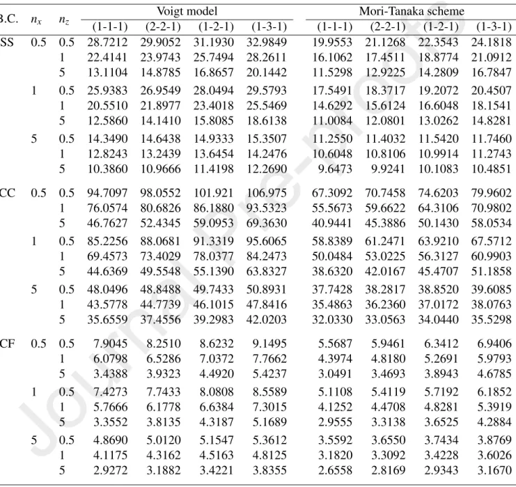
The convergence of the present enriched beam element in evaluating the fun- damental frequencies and buckling loads of the BFGSW beams is shown in Tables 4 and 5, where the fundamental frequency and buckling load parameters of the beam withL/h=10 obtained by different number of the elements are given. The results in the tables are shown for the frequencies and buckling loads based on the Voigt model only. As seen from the tables, the convergence of the enriched beam element is very fast, and the SS and CF beams require only one element to eval- uate the fundamental frequencies and buckling loads, while CC beam needs four elements. For the comparison purpose, the convergence of the conventional beam element (without enrichment) in evaluating the frequencies and buckling loads of the SS and CC beams is respectively shown in Figs. 3 and 4. In this case, the SS and CC beams require 12 and 24 conventional elements, respectively, which is much higher than the number of the enriched elements. Thus, the enriched beam element is super convergent in evaluating the frequencies and buckling loads of the BFGSW beam. Because of this convergence, one element is employed for the SS and CF beams, and four elements are used for the CC beam in all the computations reported below.
Table 1: Comparison of fundamental frequency parameter of unidirectional FGM sandwich beam with various boundary conditions (L/h=10).
B.C. Source nz Voigt model Mori-Tanaka scheme
(1-1-1) (1-2-1) (1-3-1) (1-1-1) (1-2-1) (1-3-1) CC Ref. [29] 0 11.6530 11.6530 11.6530 11.6530 11.6530 11.6530 Present 11.6649 11.6649 11.6649 11.6649 11.6649 11.6649 Ref. [29] 0.6 9.5365 9.9254 10.2040 8.2001 8.8110 9.2646 Present 9.5781 9.9596 10.2328 8.2441 8.8482 9.2960 Ref. [29] 1 8.7640 9.2984 9.6836 7.5834 8.2930 8.8304
Present 8.8049 9.3327 9.7125 7.6264 8.3300 8.8619
Ref. [29] 5 6.8298 7.6460 8.2905 6.4913 7.3003 7.9780
Present 6.8728 7.6827 8.3223 6.5349 7.3368 8.0096
SS Ref. [29] 0 5.3988 5.3988 5.3988 5.3988 5.3988 5.3988
Present 5.3933 5.3933 5.3933 5.3933 5.3933 5.3933
Ref. [29] 0.6 4.3706 4.5555 4.6894 3.7388 4.0246 4.2394
Present 4.3694 4.5532 4.6864 3.7373 4.0222 4.2363
Ref. [29] 1 4.0017 4.2539 4.4376 3.4480 3.7782 4.0314
Present 3.9994 4.2509 4.4341 3.4460 3.7755 4.0282
Ref. [29] 5 3.0937 3.4708 3.7728 2.9387 3.3101 3.6263
Present 3.0916 3.4679 3.7694 2.9365 3.3068 3.6224
CF Ref. [29] 0 1.9396 1.9396 1.9396 1.9396 1.9396 1.9396
Present 1.9382 1.9382 1.9382 1.9382 1.9382 1.9382
Ref. [29] 0.6 1.5674 1.6341 1.6825 1.3398 1.4426 1.5200
Present 1.5668 1.6333 1.6815 1.3389 1.4416 1.5189
Ref. [29] 1 1.4342 1.5251 1.5914 1.2350 1.3537 1.4449
Present 1.4332 1.5239 1.5902 1.2339 1.3525 1.4437
Ref. [29] 5 1.1074 1.2427 1.3514 1.0518 1.1850 1.2987
Present 1.1063 1.2415 1.3501 1.0506 1.1836 1.2972
Table 2: Comparison of fundamental frequency parameter of bidirectional FGM beam withL/h= 20
nx Source SS CF
nz=0 nz=0.4 nz=0.8 nz=1 nz=0 nz=0.4 nz=0.8 nz=1 0 Ref. [45] 2.8369 2.8251 2.7919 2.7685 1.0126 1.0087 0.9970 0.9873
Ref. [49] 2.8256 2.8135 2.7875 2.7656 1.0069 1.0036 0.9943 0.9865 Present 2.8371 2.8258 2.7925 2.7681 1.0130 1.0090 0.9971 0.9884 0.4 Ref. [45] 2.8320 2.8212 2.7880 2.7626 0.8955 0.8916 0.8798 0.8721 Ref. [49] 2.8211 2.8091 2.7831 2.7612 0.8943 0.8905 0.8823 0.8754 Present 2.8327 2.8214 2.7881 2.7637 0.8950 0.8914 0.8809 0.8732 0.8 Ref. [45] 2.8193 2.8076 2.7744 2.7509 0.7880 0.7861 0.7763 0.7685 Ref. [49] 2.8078 2.7957 2.7699 2.7480 0.7917 0.7884 0.7810 0.7646 Present 2.8195 2.8083 2.7751 2.7508 0.7885 0.7884 0.7810 0.7646 1.0 Ref. [45] 2.8095 2.7978 2.7646 2.7412 0.7392 0.7373 0.7275 0.7216 Ref. [49] 2.7978 2.7858 2.7600 2.7382 0.7344 0.7314 0.7245 0.7188 Present 2.8096 2.7984 2.7654 2.7411 0.7394 0.7364 0.7278 0.7214
Table 3: Comparison of buckling load parameter of unidirectional FGM sandwich beams (L/h= 20).
B.C. Source nz Voigt model Mori-Tanaka scheme
(1-0-1) (1-1-1) (2-1-2) (1-0-1) (1-1-1) (2-1-2) CC Ref. [39] 0 208.950 208.950 208.950 208.950 208.950 208.950 Present 208.951 208.951 208.951 208.951 208.951 208.951 Ref. [39] 0.5 117.103 134.288 126.304 79.9953 98.6527 89.3516 Present 117.504 134.613 126.668 80.2548 98.9009 89.6116 Ref. [39] 1 81.8104 102.474 92.4807 58.2368 76.0450 66.6233 Present 81.9926 102.665 92.6740 58.4032 76.2242 66.8015 Ref. [39] 5 41.9324 56.3501 47.8608 39.8914 50.8376 43.8049 Present 42.0775 56.4957 48.0069 40.0232 50.9694 43.9491 SS Ref. [39] 0 53.2364 53.2364 53.2364 53.2364 53.2364 53.2364 Present 53.2364 53.2364 53.2364 53.2364 53.2364 53.2364 Ref. [39] 0.5 29.7047 34.0738 32.0404 20.2586 24.9763 22.6179 Present 29.7690 34.1201 32.0943 20.2872 25.0000 22.6441 Ref. [39] 1 20.7096 25.9467 23.4088 14.7339 19.2205 16.8380 Present 20.7212 25.9588 23.4211 14.7445 19.2319 16.8494 Ref. [39] 5 10.6079 14.2191 12.0790 10.1124 12.8250 11.0579 Present 10.6171 14.2284 12.0883 10.1205 12.8311 11.0664