Receiving Party shall not be liable for the disclosure of Confidential Information that: (a) is lawfully in the public domain other than by breach of this Agreement of any duty to the disclosing party; (b) lawfully received from a third party without any obligation of confidentiality; (c) lawfully known to the receiving party, without any restriction on use or disclosure, prior to its receipt by the disclosing party; (d) independently developed by employees of the receiving party; or (e) made generally available to third parties by the disclosing party, without restriction on disclosure. Title or right to confidential information between the parties remains with the disclosing party.
Introduction
- Audience
- Reference Documents
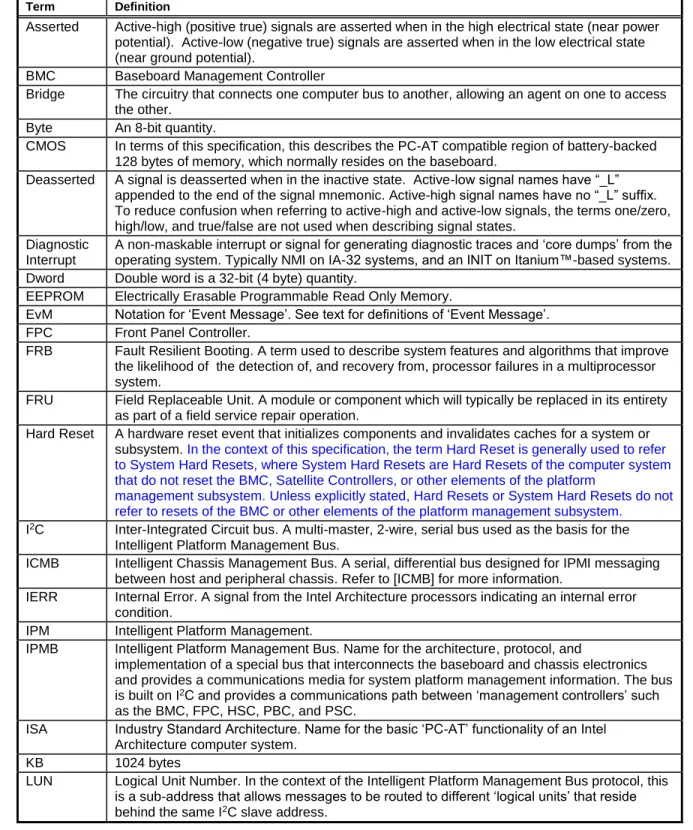
- Conventions and Terminology
- Background - Architectural Goals
- New for IPMI v
- New for IPMI v2.0
- IPMI Overview
- Intelligent Platform Management
- IPMI Relationship to other Management Standards
IPMB] Intelligent Platform Management Bus Communication Protocol Specification v1.0, ©1998 Intel Corporation, Hewlett-Packard Company, NEC Corporation, and Dell Computer Corporation. The IPMI v1.5 specification specifies how IPMI messaging can be achieved via a direct serial or external modem connection to the BMC (Baseboard Management Controller).
IPMI I/F
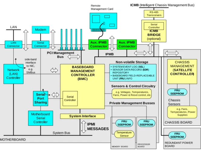
Management Controllers and the IPMB
IPMI supports the extension of platform management by connecting additional management controllers to the system using IPMB. IPMI also includes low-level I2C access commands that can be used to access "non-intelligent" I2C devices (devices that do not handle IPMI commands) on IPMB or private buses accessed through management.
IPMI Messaging
IPMB can also support SMBus slave devices, with the limitation that the SMB Alert signal is not supported on IPMB, and a controller implementing the IPMB protocol cannot serve as the target for an SMBus Modified Write Word transfer from an SMBus slave.
Sensor Model
System Event Log and Event Messages
The common request message (command) used to add events to the SEL is called an Event Message. However, this approach ties the Sensor Type and Event Type assignment to event message generation.
Sensor Data Records & Capabilities Commands
Management controllers that generate Event Messages must know the sensor and type of the event so that they can put that information in the Event Message. IPMI also includes commands that allow sensor and event type information to be read from the sensor data record and written to the controller during initialization.
Initialization Agent
Sensor Data Record Repository
Private Management Busses
FRU Information
FRU Devices
FRU SEEPROMs provide a mechanism for implementing FRU information without requiring a management controller in the field replaceable unit. Note: depending on the device type, I2C addressing places a limit on the number of devices that can be directly placed on the IPMB.
Entity Association Records
17 In order to more economically support the provision of FRU information across multiple platform modules, IPMI also allows simple 24C02-compatible SEEPROM (Serial Electrically Erasable Programmable ROM) chips to be used for storing FRU information. 24C02' type devices are non-volatile storage devices that have a built-in I2C compatible interface). FRU SEEPROMs can be accessed via a Private Management Bus connected to a management controller, or can be placed directly on the IPMB or PCI Management Bus if necessary.
Linkage between Events and FRU Information
While supported, it is generally recommended that devices with I2C/SMBus interfaces that do not have data integrity checks (eg checksums), such as 24C02-type SEEPROMs, not on 'public' buses such as IPMB and PCI-SMBus not be placed. This is because without data integrity checking it is possible that a misbehaving third-party add-on device could cause a bus 'error' which would result in an undetected error when reading or writing the SEEPROM.
Differentiation and Feature Extensibility
System Interfaces
The system interface connects to a system bus that can be driven by the main processor(s). SSIF helps support lower-cost BMC implementations by enabling an interface that can be used on low-cost microcontrollers in low-pin-count packages.
Other Messaging Interfaces
Any system bus that allows the main processor(s) to access the specified I/O or memory locations, and meets the timing specifications, can be used. The BT interface also provides an alternative to using a controller with a built-in KCS interface.
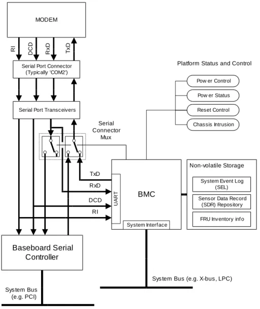
Serial/Modem Interface
The SMIC interface provides an alternative when the implementer wants to use a microcontroller for the BMC that does not have the built-in hardware for a KCS interface. PPP mode allows remote applications to take advantage of the OS's built-in PPP support for things like dialing and authentication, and provides the highest similarity to LAN-based software, but at the lowest throughput cost.
LAN Interface
PPP mode: The IPMI messages are encapsulated in the same RMCP format used for LAN messages, but are delivered via a PPP connection. Terminal mode is lower performance than basic mode and more limited in capabilities than both basic mode and PPP mode, but provides a mechanism for those transitioning to IPMI and more sophisticated interfaces from a legacy, character-based environment.
Serial Over LAN (SOL)
IPMI and ASF
LAN Alerting
Serial/Modem Alerting and Paging
Platform Event Filtering (PEF)
Call Down Lists and Alert Policies
Channel Model, Authentication, Sessions, and Users
In addition, there is a channel privilege limit that sets the maximum limit for all users on a given channel. Thus, a user can operate at a privilege level that is not lower than the user's privilege limit and the channel's privilege limit.
Standardized Watchdog Timer
The concept of the user is essentially a way of identifying a collection of privilege and authentication information. This means that a given user may have a different password and set of privileges to access the BMC through a LAN channel than through a serial channel.
Standardized POH Counter
Firmware Firewall
Command and Function Discovery
IPMI Hardware Components
Configuration Interfaces
IPMI and BIOS
System Management Software (SMS)
SMI Handler
25 The SMI handler is usually a routine that is loaded and initialized in a protected area of memory by the BIOS. This allows the SMI handler to implement its management functions in an OS-independent manner.
Overview of Changes from IPMI v1.0
Logical Management Device Types
Message Handler This logical device represents functions related to the configuration and operation of authentication and message routing, both within the BMC and between the various interfaces to the BMC. An intelligent platform management bus can be considered as defining other "logical" devices as well.

Baseboard Management Controller (BMC)
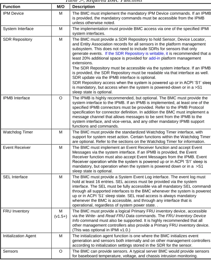
- Required BMC Functions
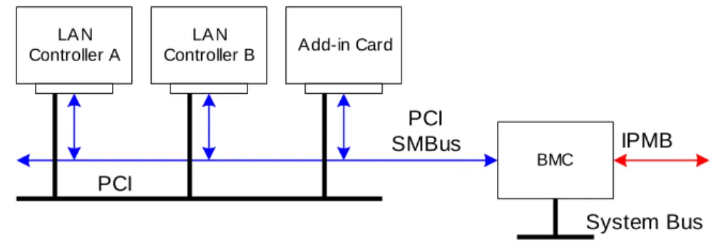
Event Receiver M BMC must implement an Event Receiver function and accept Event Messages via the system interface. System software can also access the PCI management bus by sending commands to the BMC via the System Interface.
Satellite Controller Required Functions
Message Interface Description
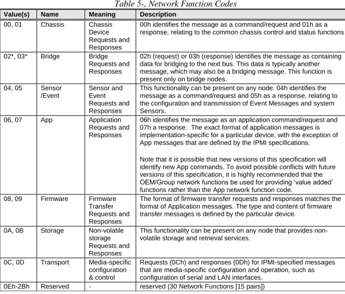
- Network Function Codes
- Completion Codes
- Completion Code Requirements
- Response Field Truncation on non-zero Generic Completion Codes
- Summary of Completion Code Use
- Sensor Owner Identification
- Software IDs (SWIDs)
- Isolation from Message Content
It is recommended that a Termination Code 00h is also returned for normal responses to OEM commands. A non-zero completion code must be returned for an error or atypical response to a standard command.
IPMI Messaging Interfaces
- Terminology
- Channel Model
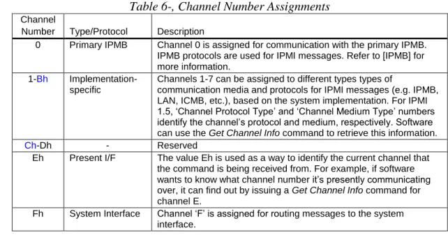
- Channel Numbers
- Channel Protocol Type
- Channel Medium Type
- Channel Access Modes
- Logical Channels
- Channel Privilege Levels
- Users & Password Support
This parameter can be used to enable the BIOS to 'answer the phone' instead of the BMC. Privilege levels tell the BMC which commands are allowed to run through the channel.
6.9.1 ‘Anonymous Login’ Convention
Anonymous Login Status
When a session is activated, the BMC will sequentially scan the usernames starting with User ID 1 and will look for the first user who has a matching username and has access enabled for the given channel. If the Set User Access command is not supported, the privilege limits for the channel are used for all users.
System Interface Messaging
- BMC Channels and Receive Message Queue
- Event Message Buffer
It is recommended that the receive message queue has at least two 'slots' for each channel. The BMC itself, if necessary, can use the Receive Message Queue and Messaging Channels to send.
System Interface Discovery and Multiple Interfaces
The receive message queue is used to hold message data for system software until the system software can collect it. System management software is responsible for emptying the receipt message queue when it contains data.
IPMI Sessions
- Session-less Connections
- Single-session Connections
- Multi-session Connections
- Per-Message and User Level Authentication Disables
- Link Authentication
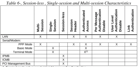
- Summary of Connection Characteristics
- IPMI v1.5 Session Activation and IPMI Challenge-Response
- IPMI v1.5 Session Sequence Numbers
- IPMI v1.5 Session Sequence Number Handling
- IPMI v1.5 Inbound Session Sequence Number Tracking and Handling
- IPMI v1.5 Out-of-order Packet Handling
- IPMI v1.5 Outbound Session Sequence Number Tracking and Handling
- IPMI v2.0 RMCP+ Session Sequence Number Handling
- IPMI v2.0 RMCP+ Sliding Window
- Session Inactivity Timeouts
The BMC and the remote console independently select an initial session sequence number for the messages they receive. The remote console must increment the incoming session sequence number by one (1) for each subsequent message it sends to the BMC.
- Additional Session Specifications and Characteristics
The BMC only checks for inactivity while the connection is switched to the BMC. The BMC terminates the telephone connection only if a session closes due to an idle timeout while the serial connection is routed to the BMC.
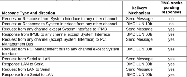
BMC Message Bridging
- BMC LUN 10b Routing
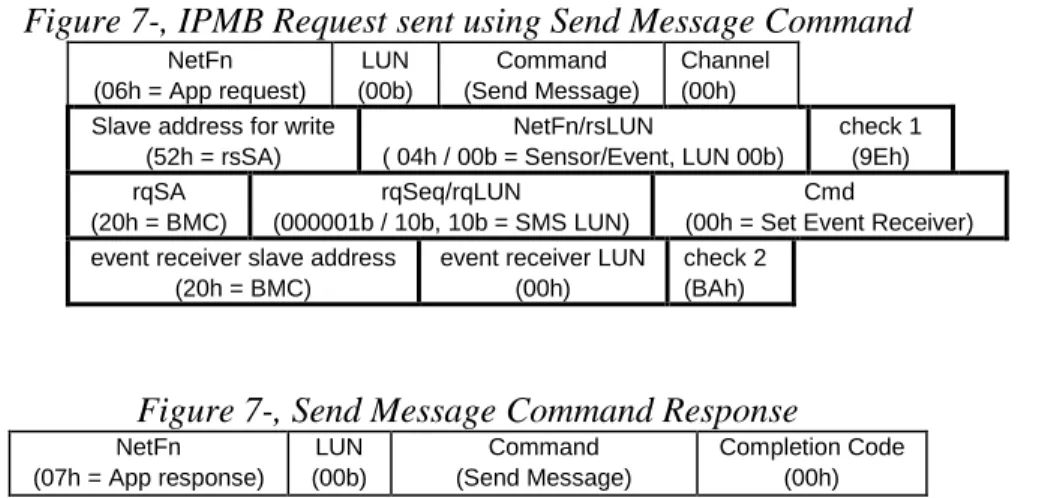
- Send Message Command From System Interface
- Send Message Command with Response Tracking
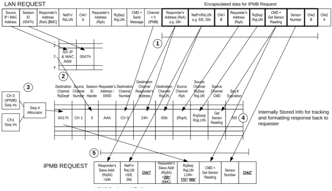
- Bridged Request Example
To the client that initiated the Send Message command, the response will appear as if the encapsulated request was executed directly by the BMC. The request is a combination of field values copied from the original send message command and values generated by the BMC.
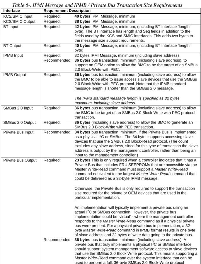
Message Size & Private Bus Transaction Size Requirements
IPMB output requires: 36 bytes bus transaction, minimum (including slave address) to allow the BMC to issue access slave devices using the SMBus 2.0 Block-Write with PEC protocol. This means supporting a Master Write-Read command over the system interface that can be used to perform a full, 36-byte SMBus 2.0 Block-Write protocol transaction.
IPMB Interface
- IPMB Access via Master Write-Read command
- BMC IPMB LUNs
- Sending Messages to IPMB from System Software
- Sending IPMB Messages to System Software
- Testing for Event Message Buffer Support
The bolded boxes show the bytes for the IPMB message transferred in the send message command. System software uses the Get Message command to read messages from the message queue.
ICMB Interface
- Virtual ICMB Bridge Device
- ICMB Bridge Commands in BMC using Channels
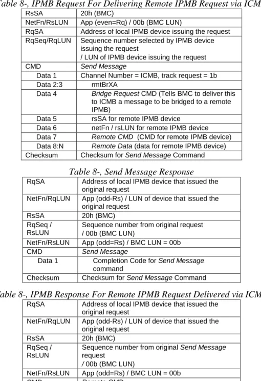
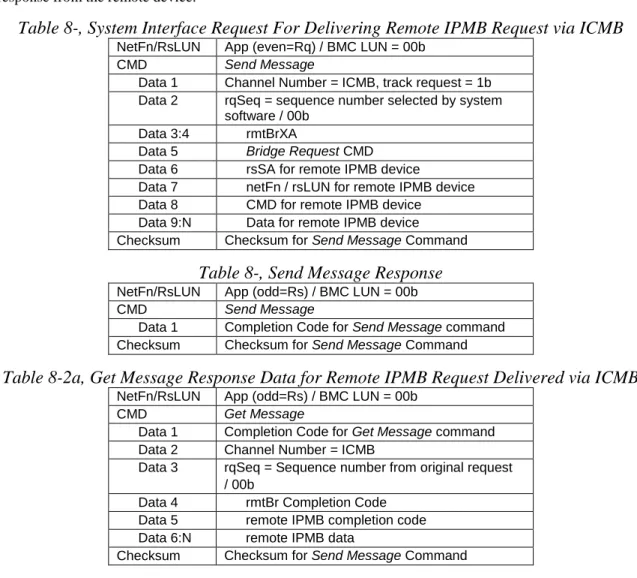
- ICMB Bridging from System Interface to Remote IPMB using Channels
- ICMB Bridging from Local IPMB to Remote IPMB using Channels
The following tables show the KCS formats of the Send Message command request and response for bridging a request to a device on a remote IPMB and the subsequent corresponding Receive Message Queue content for the response from the remote device. The main difference is that the device that originated the request later receives an asynchronous response message that appears as if the BMC is responding directly to the remote IPMB.
Keyboard Controller Style (KCS) Interface
- KCS Interface/BMC LUNs
- KCS Interface-BMC Request Message Format
- BMC-KCS Interface Response Message Format
- Logging Events from System Software via KCS Interface
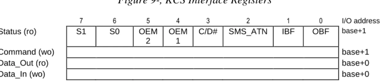
- KCS Interface Registers
- KCS Interface Control Codes
- Status Register
- SMS_ATN Flag Usage
- Command Register
- Data Registers
- KCS Control Codes
- Performing KCS Interface Message Transfers
- KCS Communication and Non-communication Interrupts
- Physical Interrupt Line Sharing
- Additional Specifications for the KCS interface
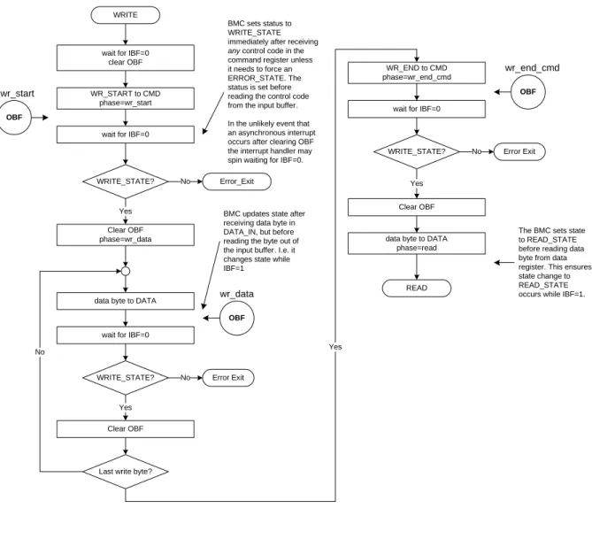
- KCS Flow Diagrams
- Write Processing Summary
- Read Processing Summary
- Error Processing Summary
- Interrupting Messages in Progress
- KCS Driver Design Recommendations
Response messages are read transmissions from the BMC to the system software via the KCS interface. The KCS interface can be used to send event messages from the system software to the BMC event receiver.
SMIC Interface
- SMS Transfer Streams
- SMIC Communication Register Overview
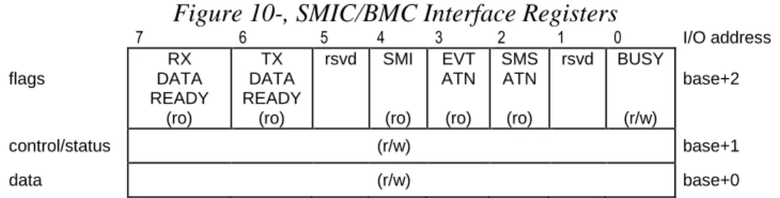
- SMIC/BMC Message Interface Registers
- Flags Register
- Control/Status Register
- a Control and Status Codes
- Data Register
- Performing a single SMIC/BMC Transaction
- Performing a SMIC/BMC Message Transfer
- Interrupting Streams in Progress
- Stream Switching
- DATA_RDY Flag Handling
- SMIC Control and Status Code Ranges
- SMIC SMS Stream Control Codes
- SMIC SMS Stream Status Codes
- SMIC Messaging
- SMIC/BMC LUNs
- SMIC-BMC Request Message Format
- BMC-SMIC Response Message Format
- Logging Events from System Software via SMIC
The BMC will only undo the RX_DATA_RDY or TX_DATA_RDY flags (0), while asserting BUSY (1). The SMIC data register must be loaded with the data byte to be written to the BMC.
Block Transfer (BT) Interface
- BT Interface-BMC Request Message Format
- BMC-BT Interface Response Message Format
- Using the Seq Field
- Response Expiration Handling
- Logging Events from System Software via BT Interface
- Host to BMC Interface
- BT Host Interface Registers
- BT BMC to Host Buffer (BMC2HOST)
- BT Host to BMC Buffer (HOST2BMC)
- BT Control Register (BT_CTRL)
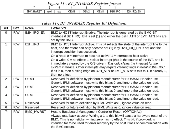
- BT Interrupt Mask Register (INTMASK)
- Communication Protocol
- Host and BMC Busy States
- Host Command Power-On/Reset States
Finally, the BMC sets an outgoing attention bit and generates an interrupt to the host (the host can optionally poll the attention bits and can enable/disable the interrupts via a MASK register). When the host writes a 1 to this bit, an interrupt is generated to the baseboard management controller.
SMBus System Interface (SSIF)
- Single Threaded Interface
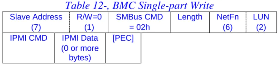
- Single-part Write
- Multi-part Write
- Error conditions for Multi-part Writes
- Single-part Read Transaction
- Multi-part Read Transactions
- Retention of Output Data
- SMBAlert Signal Handling
- Enabling/disabling SSIF SMBAlert
- Polling for output data
- SMBus NACKs and Error Recovery
- PEC Handling
- SMBus Timeout and Hang Handling
- Discovering SSIF
- SSIF Support Requirements for IPMI v1.5-only BMCs
- SSIF Support Requirements for IPMI v2.0 & Later BMCs
- Summary of SMBus Commands Values for SSIF
- SSIF IPMI Commands
- SSIF Timing
A multi-part write is used when more than 32-bytes of IPMI message data needs to be written to the BMC. The multi-part read end transaction is a Read-Block transaction that completes a multi-part read operation.
IPMI LAN Interface
- RMCP
- ASF Messages in RMCP
- RMCP Port Numbers
- RMCP Message Format
- Required ASF/RMCP Messages for IPMI-over-LAN
- RMCP ACK Messages
- RMCP ACK Handling
- RMCP/ASF Presence Ping Message
- RMCP/ASF Pong Message (Ping Response)
- RMCP+
- BMC Support Requirements for v1.5 and v2.0/RMCP+ Protocols
- Session-less Command Support
- IPMI Messages Encapsulation Under RMCP
- RMCP/ASF and IPMI Byte Order
- IPMI over LAN Packet using IPv4
- a IPMI over LAN Packet Using IPv6
- VLAN Support
- IPMI LAN Message Format
- LAN Alerting
- IPMI LAN Configuration
- IP and MAC Address Configuration
AuthCode (Integrity Data) var var For IPMI v1.5, this field is as specified by Auth Type. For IPMI v2.0 RMCP+ packets, the IPMI session trailer is absent when the session ID is 0000_0000h or when bit 6 of the payload type field indicates that the packet is unauthenticated.
13.10.2 ‘Teamed’ and Fail-over LAN Channels
ARP Handling and Gratuitous ARP
- OS-Absent problems with ARP
- Resolving ARP issues
- BMC-generated ARPs
The following are possible approaches to correct or minimize problems that may occur if the BMC LAN implementation is unable to receive or respond to ARP requests while the system is powered off or asleep. If the BMC LAN connection allows the BMC to send ARP requests, the BMC may occasionally issue gratuitous ARPs.
Retaining IP Addresses in a DHCP Environment
- Resolving DHCP issues
When the system reboots, the BMC must get a new IP address assignment in its configuration parameters. Have a system management software agent that checks the IP address assignment and updates the BMC if the assignment changes.
Typically, system software will be able to retain the address assignment while the system is running. If the system is turned off or sleeps for a long enough time, the IP address may be lost due to DHCP lease expiration.
LAN configuration parameters for IPv6 addressing and LAN signaling using IPv6 addressing should not be implemented unless IPv6 addressing is supported according to this specification.
143 When a static address is used as an IPv6 address source, the BMC may choose to use the Neighbor Solicitation message to check if this address is already in use by another device. If a conflict is detected, the BMC should not attempt to use the address, but simply report the conflict using the Static IPv6 Address Status parameter.
Discovering Support For IPMI over IP Connections
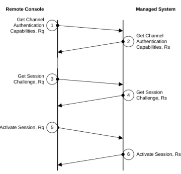
IPMI v1.5 LAN Session Activation
BMC returns a signed packet containing the session ID to be used for the active session. Console asks for information about which authentication algorithms to use to connect at a certain maximum privilege level.
IPMI v2.0/RMCP+ Session Activation
The BMC responds with RAKP Message 2 and passes a random number and GUID (Globally Unique ID) for the managed system using the remote console according to the authentication algorithm to sign a response back to the BMC. After receiving RAKP Message 3, the BMC returns RAKP Message 4 - a signed message from BMC to the remote console.
RMCP+ Session Termination
This message exchange allows a remote console to find out which IPMI version is supported. These messages are used to exchange random numbers and identification information between the BMC and the remote console, which are in effect mutual challenges for a challenge/response.
RMCP+ Open Session Request
RMCP+ Open Session request and response messages are used to enable a remote console to determine which Cipher Suite(s) can be used to establish a session at a requested maximum privilege level. The BMC can use this value to help distinguish retry messages from new messages from the remote console.
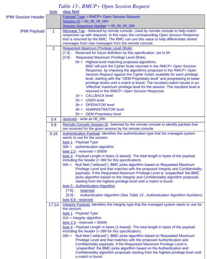
RMCP+ Open Session Response
21:28 Integrity Payload This payload defines the proposal for an integrity algorithm selected by the managed system to be used for this session (see Table 13-, RMCP+ Open Session Request for the definition of this payload). 29:36 Confidentiality Payload This payload defines the proposed confidentiality algorithm selected by the managed system to be used for this session (see Table 13-, RMCP+ Open Session Request for the definition of this payload).
RAKP Messages
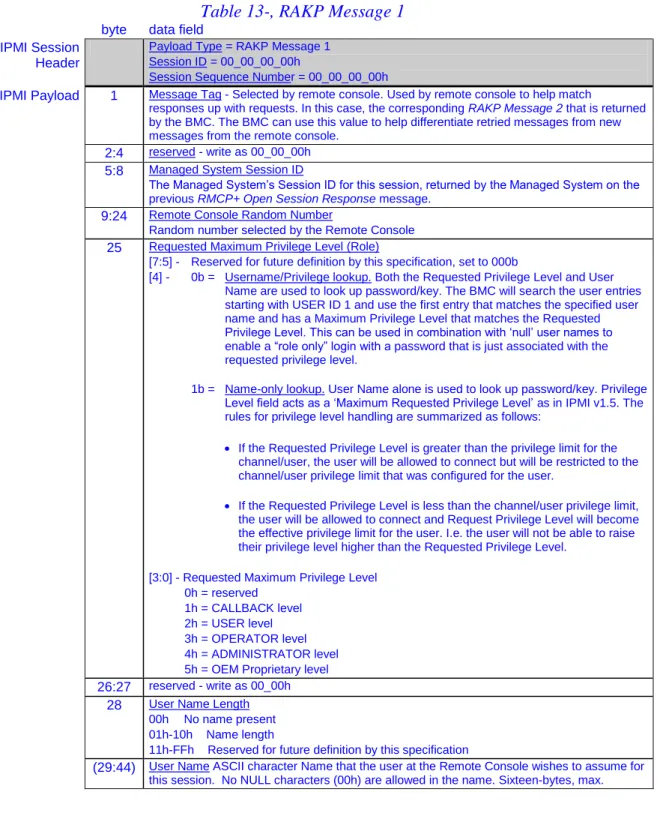
RAKP Message 1
Both the desired privilege level and the username are used to look up the password/key. If the requested privilege level is greater than the privilege limit for the channel/user, the user will be allowed to connect, but will be limited to the channel/user privilege limit that was configured for the user.
RAKP Message 2
RAKP Message 3
RAKP Message 4
RMCP+ and RAKP Message Status Codes
Differences between v1.5 and v2.0/RMCP+ Sessions
IPMI v1.5 uses a single, common session ID that identifies the session to the BMC and remote console. IPMI v2.0/RMCP+ can be configured to use a single key ("one-key") login where the user key is used for both authentication and to generate a Session Integrity Key used in integrity (AuthCode) calculations , or a "two-key" login where the user key is used.
IPMI v2.0 RMCP+ Payload Types
The BMC can be configured with 'null' usernames, whereby key lookup is performed based on 'privilege level only', or with non-null usernames, where the key lookup for the session is determined according to the username. IPMI v2.0/RMCP+ allows both the BMC and the remote console to select session IDs that identify their incoming traffic to the session.
Payloads and Payload Type Numbers
- IPMI Message Payloads and IPMI Commands
- OEM Payload Type Handles
- Payload Type Numbers
OEM Payload Type Handles are a specific numeric range of values that can be carried in the payload type field of an IPMI v2.0/RMCP+ packet. The following table defines the payload type numbers and ranges for OEM Payload Type Handles.
Authentication, Integrity, and Confidentiality Algorithm Numbers Numbers
- RAKP-HMAC-SHA1 Authentication Algorithm
- b RAKP-HMAC-SHA256 Authentication Algorithm
- RAKP-none Authentication Algorithm
- RAKP-HMAC-MD5 Authentication Algorithm
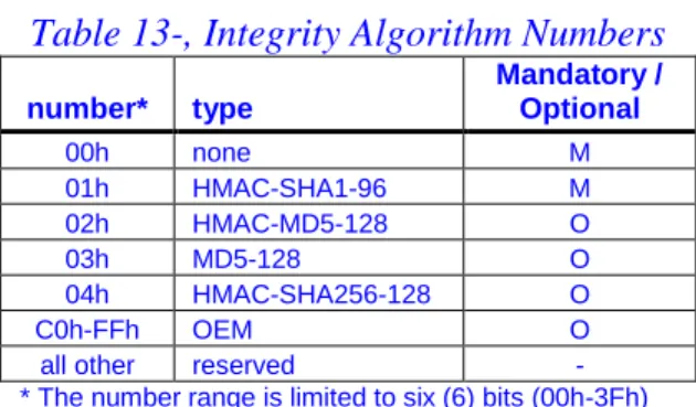
- Integrity Algorithms
- Confidentiality (Encryption) Algorithms
RAKP-HMAC-SHA1 specifies the use of RAKP messages for the key exchange portion of session establishment and that HMAC-SHA1 (per [RFC2104] ) is used to create the 20-byte Key Exchange Authentication Code fields in RAKP Message 2 and RAKP Message 3. Thus, the Key Exchange Authentication Code fields in RAKP Message 2 and RAKP Message 3 and the Integrity Check Value field in RAKP Message 4 are all 16-byte (MD5 128-bit) fields.
AES-CBC-128 Encrypted Payload Format
- Generating the Initialization Vector
- Encryption with AES
- CBC (Cipher Block Chaining)
- Generating the xRC4 Initialization Vector
- Initializing the xRC4 State Machines
K2 = 128-bit key generated from the session integrity key as described in Section 13.22, RAKP Message 3 and Section 13.32, Generating Additional Key Material. For xRC4 using a 40-bit key, only the most significant forty bits of the KRC are used.
RMCP+ Authenticated Key-Exchange Protocol (RAKP)
First, the remote console selects a random number, RM, the requested role, RoleM, username length, ULengthM, username (optional - indicated by < >. below), UNameM, and the managed system's session ID, SIDC, and sends them to the managed system as message 1 .If the request is valid, the managed system then selects a random number of RCs and sends to the remote console as message 2 the SIDM, RC, and GUIDC values and the HMAC per [RFC2104] value (SIDM, SIDC, RM, RC, GUIDC, RoleM, ULengthM, < UNameM >) created using the K[UID] key associated with the given username, UNameM, and role, RoleM.
Then the remote console sends to the managed system as message 3 the SIDC value and (for the RAKP-HMAC-SHA1 algorithm) the HMAC according to [RFC2104] the values (RC, SIDM, RoleM, ULengthM, < UNameM >) generated using the K[UID] key, selected by Username, UNameM and RoleM. After receiving message 3, the managed system checks that the SIDC value is active and then validates the message authentication code.
- Generating Additional Keying Material
- Setting User Passwords and Keys
- Random Number Generation
- Random Number Key
- Random Number Generator Counters
- Random Number Generator Operation
- IPMI Serial/Modem Interface
- Serial/Modem Capabilities
- Connection Modes
- a Detecting Who Answered The Phone
- b Connecting to the BMC
- c Connecting to the Console Redirection
- d Directing the Connection After Power Up / Reset
- e Interaction with Microsoft ‘Headless’ Operation
- f Pre-boot Only Mode
- g Always Available Mode
- h Shared Mode
The remote console can send commands to the BMC to initiate a system boot or reset. The Set Serial/Modem Mux command can be used to determine whether or not the remote console remains connected to the BMC.