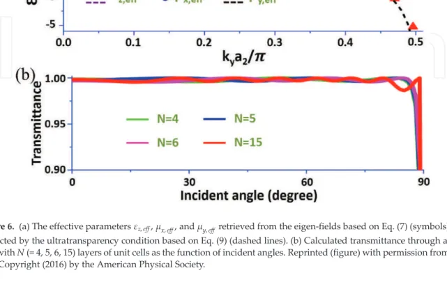
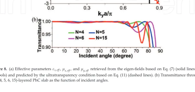
5), the surface impedance of a PhC can be calculated as long as the eigenfields of the PhC are resolved. The impedance of the PhC can therefore be rewritten as the function of effective parameters:. 7), the effective parameters of the PhC can be obtained by analyzing the eigenfields with Bloch wave vector kB¼kxbxþkyby.
In addition, in Fig. 6(a) we present the effective parameters εz,eff (square dots), μx,eff (circle dots), and μy,eff (triangle dots) of PhC based on Eq. Now, by substituting the condition μx,eff ≈1 and the dispersion equation. 4), the analytical form of the effective parameters εz,eff and μy,eff can be solved as,.
Structure-induced ultratransparency in one-dimensional PhCs
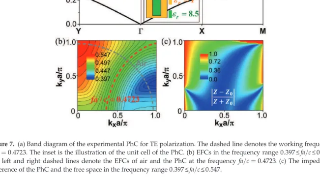
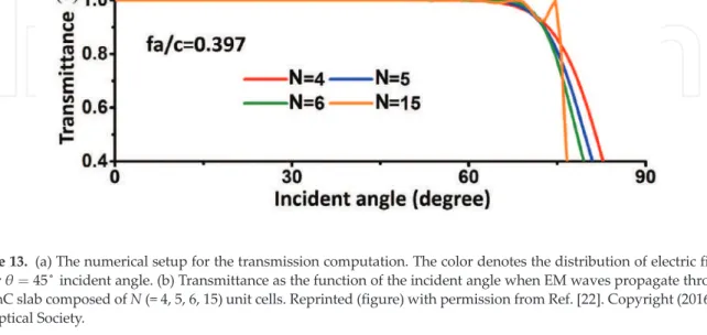
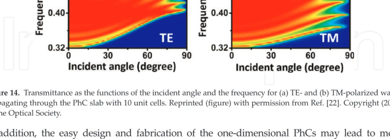
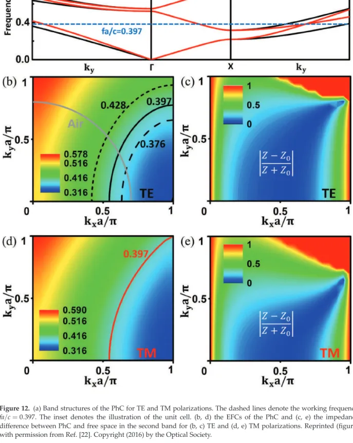
The inset indicates the illustration of the unit cell. b, d) the EFCs of the PhC and (c, e) the impedance difference between PhC and free space in the second band for (b, c) TE and (d, e) TM polarizations. In Figure 13(b) the transmission is plotted as the functions of the angle of incidence and the number of unit cells (N for the frequency fa=c¼0:397, showing N-independent almost perfect transmission for all angles of incidence of θ<70∘. Furthermore, in Figure 14(a) and (b), the transmission through a PhC sheet (N¼10) is presented as the functions of the angle of incidence and normalized frequency for TE and TM polarizations, clearly showing the broadband, wide-angle, and polarization-insensitive transparency of the PhC.
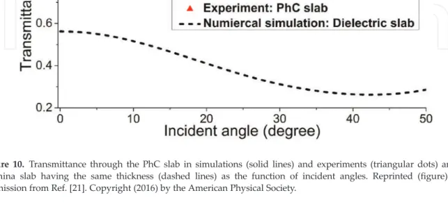
Transmittance as a function of angle of incidence when EM waves propagate through a PhC slab composed of N unit cells. Furthermore, the easy design and fabrication of one-dimensional PhCs can lead to more practical applications.
Applications
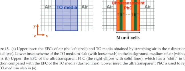
The EFC of TO medium is an ellipse that has the same height as the EFC of air in the ky direction (Figure 15(a)), like that of ultratransparent media. When the stretch ratio is greater than unity, i.e., s>1, the EFC of the TO medium (right ellipse) appears thinner than the EFC of air (left circle) in Fig. 15(a), and the grid of coordinates is looser in the x-direction in the middle TO region, as illustrated in figure 15(a). Lower inset: schematic of the TO medium plate (loose mesh) on the air background (dense mesh). b) Top: EFC of ultratransparent PhC (right ellipse with solid lines), which has a “shift” in emphasis.
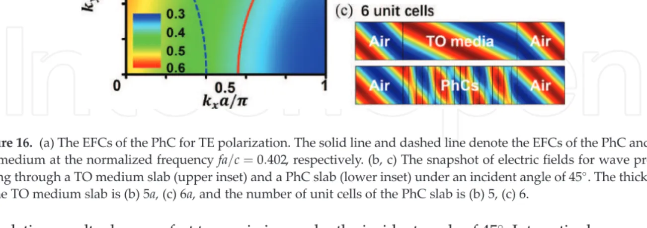
The solid line and the dotted line indicate the EFCs of the PhC and TO medium, respectively, at the normalized frequency fa=c¼0:402. Figure 19(a) and (b) correspond to the concentrator composed of the original discretized TO media and the ultra-transparent PhCs, respectively.
Conclusions and outlook
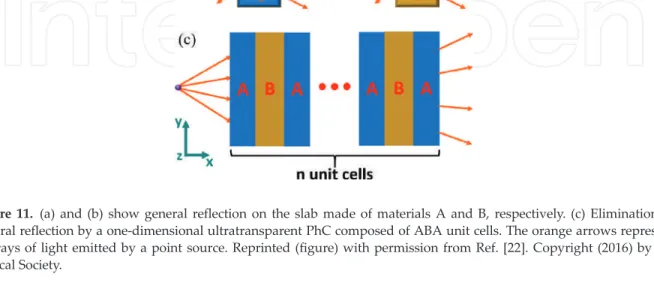
The microwave transparent wall is composed of one-dimensional ultratransparent PhCs with ABA unit cells. As we know, a wall (with a thickness of 42.5 cm) consisting of only material A or B will lead to Fabry-Pérot resonance-induced oscillation in the transmission spectrum, as shown by the Figure 20(a) and ( b). Interestingly, if we use the composite structure with ABA unit cells, broadband, wide-angle, and polarization-insensitive transparency can be obtained.
In Figure 20(c) and (d), the transmission through a wall of 10 unit cells is plotted as a function of incident angle and operating frequency for TE and TM polarizations, respectively. Naturally, almost 100% transmission is obtained in a wide frequency band (from 2.3 GHz to 2.7 GHz) and a wide-angle range (for almost all θ<60∘) for both polarizations. Although the ultra-transparency effect is mainly shown here for TE polarization, the principle is general and can be extended to TM polarization, or even both polarizations.
For example, if the PhC is ultratransparent for TE polarization, while the operating frequency falls in an omnidirectional band gap for TM polarization, such a PhC would function as an omnidirectional polarizer. The concept and theory of ultratransparency provide a guide to the pursuit of solid materials with ultimate transparency, i.e., broadband, omnidirectional, and polarization-insensitive total transparency. In the future, ultratransparent solids can be optimized to exhibit an unprecedented level of transparency and find vital applications in various fields.
This chapter is supported by the National Natural Science Foundation of China (No. Natural Science Foundation of Jiangsu Province (No. BK20170326), Natural Science Foundation for Colleges and Universities in Jiangsu Province of China (No. 17KJB140019), Jiangsu Planned Projects for Postdoc. Research funds (1701181B) and a project funded by the Priority Academic Program Development of Jiangsu Higher Education Institutions (PAPD) Selection of our books indexed in the Book Citation Index of the Web of Science™ Core Collection (BKCI).
TOP 1%
- Introduction
- Basic assembly principle for colloidal crystals
- Basic understanding of the influence of the substrate wettability on colloidal assembly from static and dynamic wettability
- Full examples for the understanding of the influence of wettability on colloidal assembly
- Superhydrophilic substrate
- Hydrophilic substrate
- Hydrophobic substrate
- Superhydrophobic substrate
- Pattern colloidal crystals from the combination of the hydrophilic/hydrophobic substrate
- Conclusions
In this paper, we presented a detailed discussion of the influence of substrate wettability on the colloidal assembly and the resulting functionality of the films. In this paper, we have presented a detailed discussion of the influence of the wettability of the substrate on the colloidal assembly and the resulting functionality of the films. Colloidal assembly has become a well-known process from more than 5 decades of colloidal assembly research [33].
The formation of colloidal assembly is mainly derived from the driven force of capillary force between the drying colloidal particles at the meniscus of the solvent [34]. In this next part we would like to discuss the influence of the substrate wettability on colloidal composition. Basic understanding of the influence of substrate wettability on colloidal composition from static and dynamic wettability from static and dynamic wettability.
Here, we understand the influence of substrate wettability on colloidal composition by qualitatively analyzing the relationship between substrate wettability on evaporation time/rate and the evaporation force as a droplet propagates over the substrate. Regarding the research progress related to the influence of wettability on colloidal composition, there are clearly more published papers after 2004 as shown in Figure 4. In comparison, the rapid growth in the number of papers related to colloidal composition/wettability occurred after the period.
In the next part, we will list a complete example to understand the influence of the substrate's wettability on the colloidal composition. Complete examples for understanding the influence of wettability on colloidal composition. Furthermore, hydrophobic substrate was used for the fabrication of the PC dome array by inkjet printing by Kuang et al.
The latex particles first collect on the surface of the suspension and then shrink with further evaporation of the solvent. Finally, we presented a summary on the influence of substrate wettability on colloidal assembly.
Author details
It is understood that the substrate with different wettability has an obvious influence on the colloidal assembly process, the resulting assembly structure and the resulting functionality, it will bring new insights for the creation of new PC optical devices.
Magnetically controlled assembly of Janus building blocks into multiplexed molecular analog photonic crystal structures. The mechanism of color change in the neon tetrafish: a light-induced tunable photonic crystal array. Transparency and damage tolerance of patternable omniphobic lubricated surfaces based on inverse colloidal monolayers.
Light manipulation by guanine crystals in organisms: Biogenic scatterers, mirrors, multilayer reflectors, and photonic crystals. Direct observation of extraordinary points in coupled photonic-crystal lasers with asymmetric optical gains. Activator with a solvent-sensitive material from inverse poly(ionic liquid) opals based on gradient Gewetting.
Ease of fabrication of a superhydrophilic-superhydrophobic patterned surface by inkjet printing of a sacrificial layer on a superhydrophilic surface. Photonic crystal domes with inkjet printing pattern for wide viewing angle displays by controlling the sliding three-phase contact line. Avoiding a coffee ring structure based on hydrophobic silicon pillar arrays during single-drop evaporation.
Controllable Fabrication of Non-Iridescent Microshaped Photonic Crystal Assemblies by Dynamic Three-Phase Contact Line Behavior on Superhydrophobic Substrates. Hybrid top-down/bottom-up strategy using superwettability to fabricate patterned colloidal assembly. Facile fabrication of a superhydrophobic cage by laser direct writing for site-specific colloidal self-assembled photonic crystal.
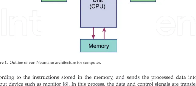
The Dawn of Photonic Crystals: An Avenue for Optical Computing
- Computer architecture
- Planar photonic crystals
- Logic gates using photonic crystals
- Optical memory using photonic crystals
In this way, the light limitation for the defect is in the horizontal plane of the PhC plate, while the vertical directions remain unconstrained [16]. The optical Kerr effect is responsible for the change in the refractive index corresponding to the intensity of the light source [28]. In this way, the nonlinear response of the medium can be well used to realize logic gates in PhC boards.
The truth table of a logic circuit represents the output of the circuit under various input conditions. On the other hand, when the optical pulse passes through the input waveguide, the refractive index of the medium decreases due to the negative nonlinearity of the medium. In addition, based on the resonant wavelength of the nanocavity, three types of cavities are possible.
When an incoming radiation satisfies the cavity resonance condition [32],. is allowed to pass through the cavity. 3), the length of the cavity dis, λ is the wavelength of light, pis an integer, and n is the index of refraction of the medium inside the cavity given by Eq. From this equation, it is clear that the resonance wavelength of the cavity is determined by the length of the cavity and the refractive index of the medium.
In this way, when the refractive index of the medium is changed by the input pulse, the resonance state of the cavity sets in, allowing light to pass through the cavity. If there is no input light pulse, the resonance state of the cavity is disturbed, resulting in blocking of the light. For the rest of the cases, the output of an AND gate turns out to be a logic zero.
Whenever the cavity is placed in resonance, there is light in the output wave, indicating the logic state of the cavity and vice versa. The light in the output wave can be used to identify the instantaneous state of the cavity.