The reuse of recycled textile waste in the textile industry is called closed-loop recycling [2]. Since the fiber breaks are created in the mechanical recycling of cotton [59, 62], low performance fabrics can be obtained that are not suitable for professional wear such as work wear, personal protective equipment, career wear and uniforms [63].
Branded sustainable textile fibers
From this point of view, economic conditions play a role in the recycling of PAN. As they stated, they are making a number of changes to the process to be more environmentally friendly.
Sustainability certifications for textiles and textile eco-labels
It brings together the environmental impacts of the studied product or service through the value chain [104]. They assess the social and environmental performance of the value chain along with the environmental impacts of the products.
Conclusions
This chapter is distributed under the terms of the Creative Commons Attribution License (http://creativecommons.org/licenses/by/3.0), which permits unrestricted use, distribution, and reproduction in any medium, provided the original work is properly cited .
TOP 1%
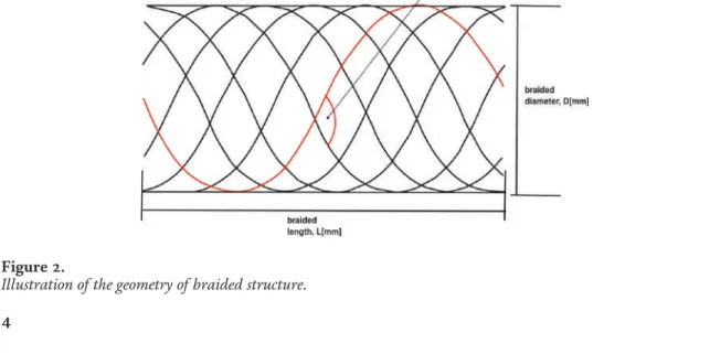
Design of braided reinforcement structure
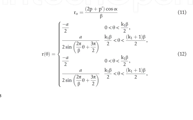
The design of the braided structure was carried out by modeling the circular coordinate of the helical path in three-dimensional space in a clockwise and anti-clockwise direction. The general coordinates of the spiral path of the yarn clockwise and counter-clockwise as (Figure 1):. 10) Generic designs of knitted fabrics can be modeled by forming the coordinates for the yarn path by imputing the values of the parameters ro and r(θ) into Eqs.
Materials and methods
Quasi-static structural analysis was performed for both the models of the singlet configurations (SC1,θ= 120 and SC2,θ= 90). The lower end of the femur bone was fixed to mimic the normal human postural condition in all the analyses. The total load in the femur von Misses stress and total strain in Z-axis were evaluated for an intact femur, then for a fractured femur and finally for a reinforced femur.
Femur bone structure models showing: (a) single posture configuration (SC1θ= 120); (b) position of the femur fracture on the bone; and (c) single pose configuration (SC2θ= 90).
Validation
Results and discussions
The deformation of the femur bone was analyzed for the SC1 conditions because it had higher mechanical properties than the SC2 posture as shown in the results. This is illustrated by the contour diagrams for the von Misses stress on the surface of the femur bone. a) The illustration of load against displacement for human femur drop and ankle configuration for an intact bone structure; and (b) the illustration of stress versus displacement for human femur fall and ankle configuration for an intact bone structure. a) The illustration of load against displacement for human femur fall and ankle configuration for a fractured bone structure; and (b) the illustration of stress versus displacement for human femur fall and ankle configuration for a fractured bone structure. a) The illustration of load against displacement for human femur drop and ankle configuration for a braid-reinforced femur bone structure; and (b) the illustration of stress versus displacement for human femur drop and ankle configuration for a braid-reinforced femur bone structure. The deformation in the fractured femur shown in Figure 10 shows that the femur bone deformation would be higher than that of the intact femur, there was also evidence of the bone yielding at lower stress levels, depicted by the levels of von Misses stress contour plots .
Contour plot of the deformation of the model of the intact femur during stance configuration. Contour plot of the deformation of the model of the fractured femur during stance configuration. Contour plot for deformation of the model of the braid-reinforced femur during stance configuration.
The illustration of quasi-static energy analysis for the simulations for (a) intact bone structure of the femur; (b) fractured bone structure of the femur; and (c) reinforced bone structure of the human femur.
Quasi-static analysis
The results predicted in simulation models show a trend where the load values were higher than the values in the fall configuration, these results were consistent with the findings elsewhere [17] where the fracture load registered higher loads in a standing configuration than in a fall configuration of the femur. The results further showed that while the force applied to the femur could deform the bone to some extent, the reinforced bone structure better withstood the loads. This was illustrated by the small deflection and minimal yield stress in the reinforced femur.
This is further supported by the large deflection in the femur with the oblique cut, when the cut was reinforced using the braided structure the deflection decreased.
Conclusion
Comparison of the elastic and yield properties of human femoral trabecular and cortical bone tissue. Prediction of fracture load at different skeletal sites by geometric properties of the cortical shell. This chapter provides a comprehensive overview of the recent developments in the design of areca fiber composites.
The physical, mechanical and thermal properties of areca fiber and its composites are explained here. The species of Areca fiber represents the Arecaceae/Palmae family (like coconut/palm trees) in terms of its physical and mechanical properties. Researchers have identified that areca fiber has future applications as an alternative to reinforced polymer composites in the automotive, aerospace and construction industries.
This chapter provides information on the development and investigation of the mechanical behavior of a natural fiber reinforced epoxy composite of areca fiber with different configurations of areca fiber orientation.
Introduction
- Thermal properties of areca fibers
- Mechanical properties of areca fiber
Furthermore, it has been shown that the strength and stiffness of natural fiber polymer composites are mainly influenced by fiber strain. Due to their good mechanical properties and biodegradability, natural fibers have a key reinforcing function and are available in many parts of the world. Fiber length is considered important for fiber utilization, especially in the traditional fiber industry [12].
Studies have been carried out on fiber hybridization in relation to kenaf and glass fibers to determine its effect on the tensile and impact properties of the materials thus produced [27]. Single fiber tensile testing was used to assess the mechanical properties and provide some basic information needed to plan the potential uses of plant fibers. On the other hand, chemical modification also determines the mechanical properties of the fiber.
The modification results in surface roughness and fibrillation due to the exclusion of cementing materials leading to improved mechanical properties of the fiber reinforced composite [42].
Fabrication of natural fiber reinforced composites
- Composites reinforcement of the fibers in the polymeric matrix to improve strength, stiffness, and fatigue resistance
- Mechanical properties of areca reinforced polymeric composites
- Areca-based hybrid composites
- Mechanical properties of areca-based hybrid composites
However, a 40 wt% fiber-reinforced areca shell-reinforced unsaturated polyester composite has been observed to yield improved mechanical properties. It has been found that there is a degradation of thermal and mechanical properties at excessive fiber loading of 8% of fiber content. In the case of reinforced polymer composites, hybridization of areca fibers with other fibers has been considered in this case.
On the other hand, the hot pressing method has been adopted to produce glass fiber shell reinforced polyethylene composites. The compression molding technique has been adopted in the hybridization of areca shell-fiber-reinforced unsaturated polyester and areca shell-fiber-reinforced epoxy composites [53]. On the other hand, the hot pressing method has been adopted in the production of shell-glass fiber reinforced polyethylene composites.
It was found that the entire spectrum of composite properties is significantly influenced by the fiber content [57].
Evaluation of mechanical properties
- Uses
It was observed that there is an increase in the tensile and flexural strengths due to an increase in the content of betel nut fiber rather than that of sisal fiber. Due to an increase in the volume fraction of fiber in the composite, there is an increase in dielectric strength of betel nut (Bn) composites. Depending on the availability, cost-effectiveness and good strength of areca fiber composites, they are used in the design of lightweight materials used in car body construction, office furniture packaging industry, partition panels and others compared to wood-based plywood or particleboard [67–69 ].
In the case of end uses associated with a small load, investigations have been carried out on composites of caustic treated areca fibers, which have been found to have improved mechanical properties to a certain extent in areca fibers. In the case of end uses requiring high tensile strength, natural rubber compounds reinforced with chemically treated areca fibers have been considered. In the case of structural and non-structural applications such as suitcases, mailboxes, grain storage, automotive interiors, partition boards and interior applications, untreated, chopped natural fiber reinforced polymer matrix bio-composites are used good.
In case of end applications requiring high flexural strength, chemically treated areca fiber reinforced epoxy composites for applications where high impact strength is required, 60% fiber loading was considered.
Characterization
Studies have been carried out on the physical, mechanical and thermal properties of areca fiber and its composites. Numerical and experimental analysis of tensile properties of banana and glass fiber reinforced epoxy composites. Effect of fiber orientation on the tribological performance of jute-reinforced epoxy composites considering different mat orientations.
Physical, mechanical and ballistic properties of Kenaf fiber reinforced polyvinyl butyral and its hybrid composites. Influence of fiber surface treatment on physico-mechanical properties of betel nut and glass fiber reinforced hybrid polyethylene composites. Investigation of 3-point bending analysis of untreated natural Areca sheath fiber reinforced polymer matrix biocomposites.
Study on Tensile Analysis of Untreated Chopped Natural Areca Casing Fiber Reinforced Polymer Matrix Biocomposites, International Journal of Engineering Research and Advanced Technology (IJERAT).