Can we use the enormous computing power available today to advance our understanding of how the brain processes information? Can we use our growing understanding of the brain to build better, more efficient, fault-tolerant computers?
Ada Lovelace
But all interesting information processing takes place at intermediate scales accessible neither by bottom-up neuroscience nor by top-down brain imaging. She lived before Ramón y Cajal's discoveries about the details of the neuron, but even today, with all the detailed knowledge accumulated in the intervening years, her agenda would be considered too ambitious.
Alan Turing
Turing figured that all a computer needed to pass his test, compared to the Manchester Baby machine, was more memory, about a gigabyte (a billion bytes) should be enough. Baba has 128 bytes of memory and could execute about 700 instructions per second.) He thought that by the turn of the 21st century computers might have that much memory. Indeed, by the turn of the 21st century, a typical desktop computer would have about a gigabyte of memory, and it would be a million times more powerful than the Baby, but it would not pass Turing's test.
Reinventing Neural Networks − Early Thoughts
Mighty ARMs from Little Acorns Grow
Why has human-like artificial intelligence proved so much more difficult than Turing and many others since him predicted. Maybe it's because we still don't understand natural intelligence, so we don't know exactly what it is we're trying to reproduce in our machines.
Realising Our Potential
Reinventing Neural Networks
The Architecture Comes Together
- The State of the Neuromorphic Art
- What Could We Bring to Neuromorphics?
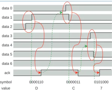
- Multicast Packet-switched AER
- Optimise, Optimise…
- Flexibility to Cope with Uncertainty
- Big Memories
- Ready to Go
Biological systems can have enormous numbers of neurons – the human brain has almost a hundred billion – so something more than AER is needed if we want to approach such scales of networks. Our digital design background naturally got us thinking about digital implementations of the neuron and synapse equations.
A Scalable Hardware Architecture for Neural Simulation
- Introduction
- Intellectual Property
- Market Opportunity
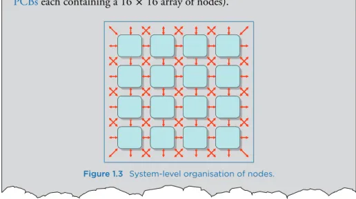
- System Organisation
- Node Organisation
- System Architecture Issues
- Development Plan
The advantage of the SoC structure is that it essentially consists of multiple copies of the fascicle processor. Each node has about the performance of a personal computer (PC) in this application and is less than 10% of the price.
Summary
It builds up a Python machine representation to be used in the rest of the toolchain. This is done by running some of the algorithms in the mapping phase (see below).
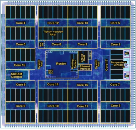
The SpiNNaker Chip 17
Architecture
- An Overview
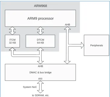
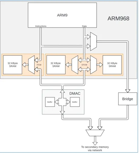
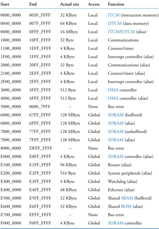
- Processor Subsystem
- Router
- Interconnection Networks
- The Rest of the Chip
This means that a single packet delivered to a processor can be multicast by software to the neurons - the last branch of the tree. Logically, each router checks the (neuron) source ID - the only information in the packet - and looks for a whole number of outputs, potentially including both chip-to-chip links and processor systems on that chip itself.
Multiprocessor Support
As part of the support for larger systems, there was a (crude) attempt to build a thermometer into each chip. This is possible because the properties of electronic components – especially speed – change with temperature.
Event-Driven Operation
Chip I/O
Monitoring
Emergency routing modes are included so that any redirection that would otherwise be invisible can be detected. As a bonus, the filters can be used to enable interrupts so that the passing of a certain kind of packet can attract immediate attention from the monitor's (or other) processor.
Chip Details
External synchronous IP was provided in RTL Verilog, which was also used to develop most internal designs, while asynchronous IP was provided in port-level technology-mapped Verilog. The design methodology has been refined with special emphasis on the energy efficiency of the clock networks.
Design Critique
In practice – again partly due to increasing ambitions – processors are active most of the time if natural, biological speeds are modeled in a 1:1 ratio. Peer-to-peer signaling in application processors could also be useful in extending the flexibility of chips that perform the tasks of non-spiking neurons.
Summary
The first stage of execution is to detect the machine to be executed. We adhere to the use of sharp neurons, embracing the main purpose of the machine.
Building SpiNNaker Machines 52
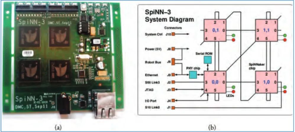
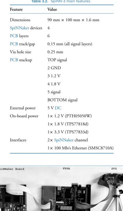
SpiNN-3: Development Platform
In addition, two inter-chip SpiNNaker channels have been exported to connectors and can be used to connect to other SpiNNaker boards or to external neuromorphic devices, such as a Dynamic Vision Sensor (DVS, also known as a silicon retina or event camera. SpiNN- 3 boards during the design, verification and testing of the various software components described in Chapter 4, as well as training SpiNNaker users.
SpiNN-5: Production Board
Additionally, a single cross-chip SpiNNaker channel is exported to a connector and can be used to interface with external neuromorphic devices. Instead, as its name implies, it is used to control the operation of the SpiNN-5 board.
Nobody is Perfect: Testing and Blacklisting
Channel test Identify malfunctioning channels between chips Power on/restart Identify interrupt devices and channels. As explained in Chapter 4, the host reads information from the SpiNNaker engine to map the application only to properly functioning devices and channels.
Putting Boards Together
- SpiNNaker Topology
- spiNNlink: High-speed Serial Board-to-Board
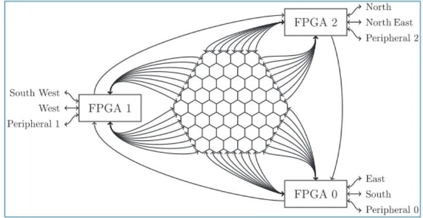
In networks with homogeneous link throughput, the duplex bandwidth is determined by the number of links cut by a balanced network partition. The hexagonal arrangement of the chips is also efficient in the number of SpiNNaker channels on the board boundary.
Putting Everything Together
- SpiNNaker1M Assembly
- SpiNNaker1M Interconnect
- SpiNNaker1M Cabling
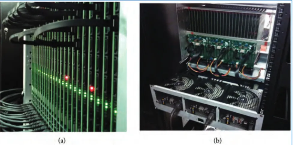
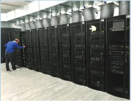
One of the coolers with the associated chimneys and plenum can be seen in Figure 3.17. The naive arrangement of units in this topology results in a long cable connecting the units at the ends of the ring (Figure 3.13(a)).
Using the Million-Core Machine: Tear it to Pieces
For any given span, the shortest length of cable that provides at least 5 cm of slack was used. The requester must keep the job alive by contacting the Spalloc server periodically and must release the allocated machine when it is done.
SpiNNaker1M in Action
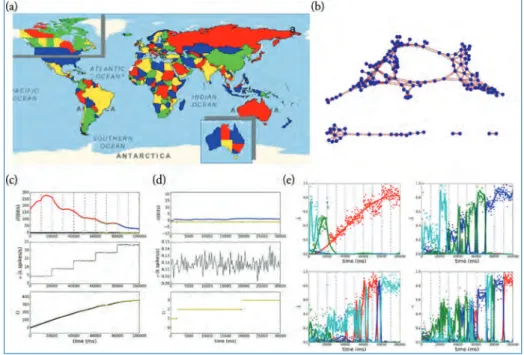
Figure 5.20(c) and (d) show the time dependence of entropy (top), firing rate (middle), and number of countries visited (bottom) for the world and Australia maps, respectively. Thus, we eliminated all the null values of the kernels in the first convolutional layer.
Stacks of Software Stacks 77
Making Use of the SpiNNaker Architecture
A small amount of data can be shared with cores running on other chips, including through communication via the SpiNNakerrouter. This, along with the low power requirements, makes the device particularly useful for robotic applications, as the board can be connected directly to the robot without the need for other equipment.
SpiNNaker Core Software
The only requirement is that the external devices must be configured to communicate with the computer using the SpiNNaker packages. Priority 1 and 2 callback jobs can be queued (queues with a maximum length of 15), with new events added to the back of the queue.
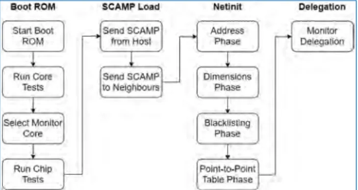
Booting a Million Core Machine
The processor selected as monitor now performs additional tests on the shared parts of the chip. Each SCAMP sends its perceived dimensions of the machine based on the dimensions received from its neighbors.
Previous Software Versions
Data Structures
- SpiNNaker Machines
- Graphs
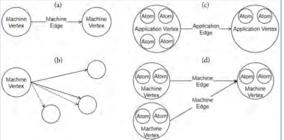
Application Vertex provides a method that returns the resources required by a continuous region or slice of the atoms in the vertex; this is specific to the exact range of atoms, allowing different atoms in the vertex to require different resources. The Application Vertex also defines the maximum number of atoms that the application code can maximally execute on each core of the machine (which can be unlimited) and also the total number of atoms that the vertex represents.
The SpiNNTools Tool Chain
- Setup
- Graph Creation
- Graph Execution
- Return of Control/Extraction of Results
- Resuming/Running Again
- Closing
- Algorithms and Execution
- Data Recording and Extraction
- Live Interaction
- Dropped Packet Re-Injection
- Network Traffic Visualisation
- Performance and Power Measurements
Data generation can also create a statistical description of the data to be loaded and then extend this data by executing a binary file on the machine. At this point, the toolchain must decide which of the above steps to redo.
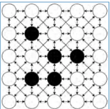
Non-Neural Use Case: Conway’s Game of Life
It is assumed that we have built the application code that will update the cell based on the state of the surrounding cells. It can then query the recorded states of each of the vertices and display this data in an appropriate manner.
- PyNN
- sPyNNaker Implementation
- Preprocessing
- SpiNNaker Runtime Execution
- Neural Modelling
- Auxiliary Application Code
Finally, the_dma_complete_callback executes in aDMAcompleteevent and starts processing the synaptic input(s) to the post-synaptic neuron(s). Therefore, one task of _dma_complete_callback is to convert the synaptic row into individual post-synaptic neuron inputs.
Software Engineering for Future Systems
The postsynaptic core also performs additional processing while looking up the source vertex in the main population table. An additional row must be added to identify peaks traveling directly from the presynaptic nucleus and also those sent from each individual delay phase of the delay elongation.
Full Example Code Listing
A diverse range of applications is also encouraged by the software stack maturity discussed in Chapter 4. We start by first presenting an art exhibition and SpiNNaker's place in it - we start lifting.
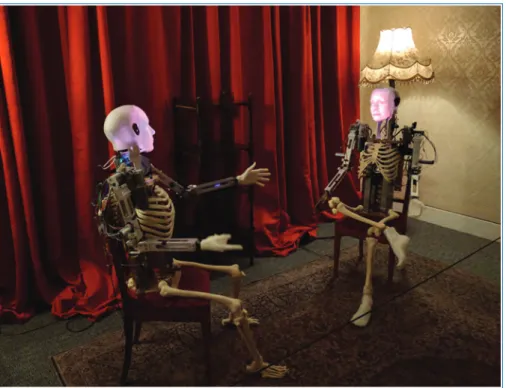
Robot Art Project
- Building Brains with Nengo and Some Bits and Pieces
The two distributed instances of the Furhat controller communicate over the network at key moments that advance the scripted dialogue. Figure 5.4 shows the operation of one of the arms in a robot over a period of 15 seconds.
Computer Vision with Spiking Neurons
- Feature Extraction
Figure 5.8 shows the output of the network; it can be seen that the maximum activity is present in the medium resolution class (Figure 5.8(b)) as it fits the input activity better. Conversely, when they reach the neuron in the right sequence, they will cause activation.
SpiNNak-Ear − On-line Sound Processing
- Motivation for a Neuromorphic Implementation
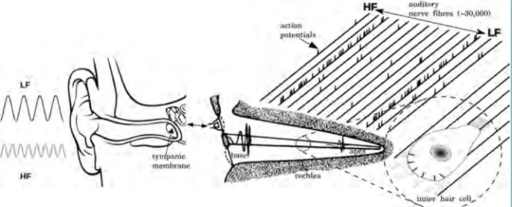
- The Early Auditory Pathway
- Model Algorithm and Distribution
- Results
- Future Developments
The neuromorphic hardware experiences an increase in energy consumed due to the increasing size of the machine being used (number. It has been shown that descending projections can provide useful feedback modulation to the incoming sound representation, 'tuning' the representations of learned salient stimuli [252] and producing stimulus-specific adaptation in sensory neurons [153].
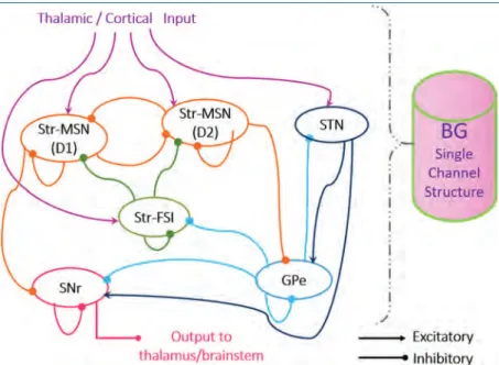
Basal Ganglia Circuit Abstraction
Model results on SpineML show qualitative similarities with those on SpiNNaker in terms of base firing rates of the single-channel BG model cell populations. Implementation of the three-channel model on SpineML, which follows exactly the same implementation procedures as onSpiNNaker, demonstrates action selection through a larger input and is shown in Figure 5.18(b).
Constraint Satisfaction
- Defining the Problem
- Results
- Graph Colouring
- Latin Squares
- Ising Spin Systems
The classification is considered successful if the number of output events of the correct category is the maximum. In these experiments, we kept the elimination of the zero core elements in the C1 layer.
From Activations to Spikes 160
Symbol Card Recognition System with Spiking ConvNets
- Spiking ConvNet on SpiNNaker
- Results
Another feature of the ConvNet is that most of the neuron parameters (such as neuron voltage thresholds, voltage reset levels, leakage rates and refractory times) are shared by all the neurons in the same population. In Figure 6.4(b) we have plotted the total number of output events generated at the output of the SpiNNaker classifier as a function of the input stimulus delay factor.
Handwritten Digit Recognition with Spiking DBNs
- Results
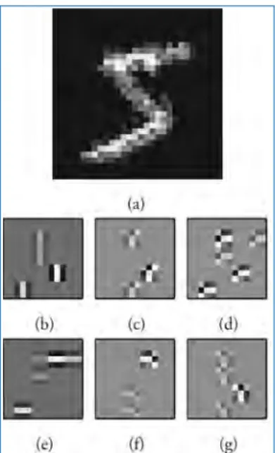
Figure 6.8 demonstrates the effect of reduced bit precision on the trained weights of spikingDBNof O'Connor et al.[183]. The receptive fields of the first 6 neurons (rows) in the first hidden layer of the DBN with the two hidden layers.
![Figure 6.6. An RBM with full connectivity between visible units (bottom) and hidden units (top), but no connections within the same layer [241].](https://thumb-ap.123doks.com/thumbv2/1libvncom/9200696.0/193.663.189.491.87.229/figure-connectivity-visible-units-hidden-units-connections-layer.webp)
Spiking Deep Neural Networks
- Related Work
- Siegert: Modelling the Response Function
- Generalised Off-line SNN Training
- Results
- Summary
Learning in Neural Networks 205
Spike-Timing-Dependent Plasticity
- Experimental Evidence for Spike-Timing-Dependent Plasticity
- Related Work
- Implementation
- Inhibitory Plasticity in Cortical Networks
- The Effect of Weight Dependencies
Voltage-Dependent Weight Update
- Results
Neuromodulated STDP
- Eligibility Traces/Synapse Tagging
- Credit Assignment
Structural Plasticity
- Topographic Map Formation
- Stable Mappings Arise from Lateral Inhibition
- MNIST Classification in the Absence of Weight
- Visualisation, Visualisation, Visualisation
- Rewiring for Motion Detection
Neuroevolution
- Pac-Man on SpiNNaker
- Further Exploration of NEAT
- An Evolutionary Optimisation Framework for SpiNNaker
- Methods
- Results
- Future Work
Creating the Future 262
SpiNNaker2
- Lessons from SpiNNaker1
- Scaling Performance and Efficiency
SpiNNaker2 Chip Architecture
SpiNNaker2 Packet Router
The Processing Element (PE)
- PE Components
- PE Implementation Strategy and Power Management
Summary