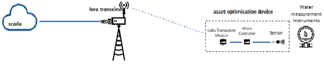
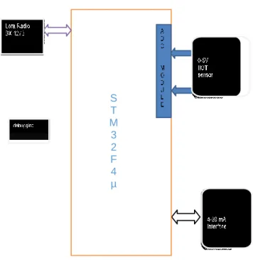
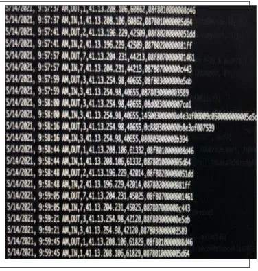
3 Figure 1.2 Diagram of the analysis of sensor data using LoRa endpoint and Gateway 12 Figure 1.3 A high-level overview of the Research Proposal 19 Figure 1.4 The hardware structure of the proposed logger with LoRa Radio. 66 Figure 3.3 Top and bottom view of Mother unit of Legacy GSM Logger 68 Figure 3.4 Screen capture of the serial port of legacy data logger 69.
Proposal
Introduction
This chapter consists of two parts, the proposal document before embarking on the implementation of the results of this research. The second part of this chapter covers other preliminary matters not included in the proposal document.
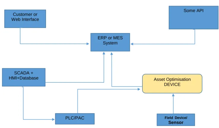
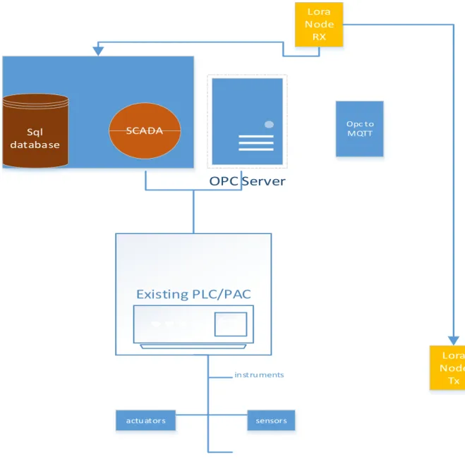
Existing and Proposed architecture for Modern Process Control Systems
The cost of physically adding the extra section to the process control system is too high because there is no more capacity in the physical infrastructure (current process control system/PLC). To expand data analysis that was not previously part of the existing process control system.
Statement of Research Problem
Current SCADA systems meet most of these needs at very high prices and through appropriate protocols. The high cost of these infrastructure assets and the consequence of failure of these assets creates a crucial need for an asset management tool.
Project Constraints
This design has implementation at various levels of the value chain, from hardware implementation to low-level programming to data transfer to high-level programming. The software implementation of this project requires the system to run for extended periods of time to ensure an accurate evaluation of the systems.
Background and relevance of proposed Project
In this study, this research was mainly looked at because of the number of communication interfaces implemented in the design. Much of the literature review will relate to research studies addressing the various protocols in this study.
Structure of the Thesis
A laboratory testing process will be used to prove the concept of the above project. This GUI and visualization will be implemented in this project, but the data will be visualized remotely via a web application.
Research deliverables
We will require a graphical USER interface for remote viewing of Dash Board type data displayed a remote data center relayed via the GSM/LTE network. Document preparation will be ongoing and will be completed once the hardware is developed and tested.
Delineation of the thesis
This research will look at opportunities to transfer data using different protocols in the IIOT space. This research will also form the basis for providing automated process control systems for unmanned systems.
The Significance of the research project
The important contribution of this research is the presentation of process control data at different levels of the data value chain with reasonable data costs. This research aims to lay the foundation of data acquisition to drive business, using process control data and plant performance indicators to drive KPIs.
Research Methodology
The biggest challenge in this research was wearing different hats at the different levels of the data value chain. Data interoperability also required a full understanding of the data value chain from the sensor level up to high level application software.
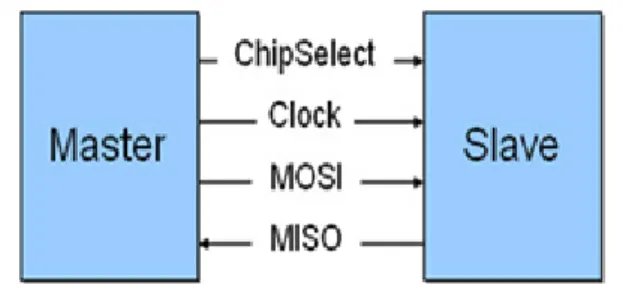
Serial Peripheral Interface Protocol (SPI)
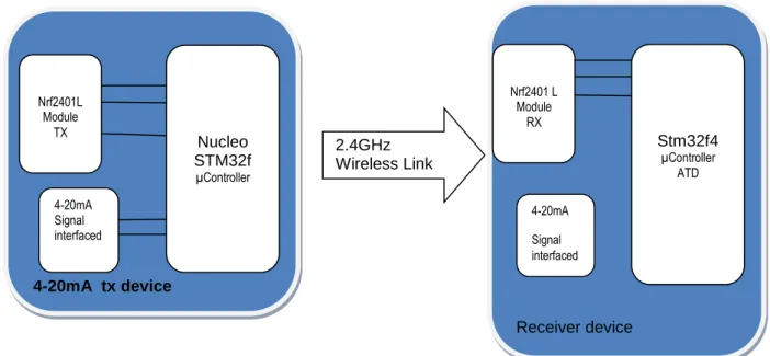
The signal current is not affected by this voltage drop as long as the power supply voltage is greater than the sum of the voltage drops around the loop at the maximum signal current of 20 mA. The 4-20 ma standard is adapted for process control systems, especially for signals with long wire runs and their robustness. In the low power wan, the implementation of the industrial sensor using a 4-20 mA input signal can be challenging due to its power demands in the standard implementation.
Reading the 0-10V signal for transmission
- Nrf24L01
- LoRa
- LoRa PHY
- LoRa Transmitter module
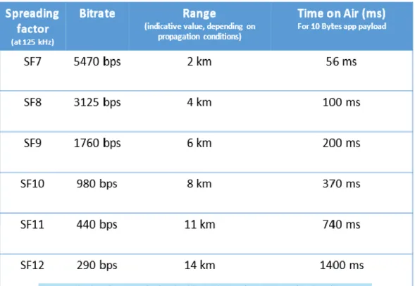
Like many other link layer protocols, LoRa® adds additional constant factors to each transmitted packet to increase the ToA. i) The preamble, necessary for synchronization of receiver and transmitter. Both variations of the LoRa transmitter modules are essentially the same, depending on which sensor type is connected to the microcontroller.
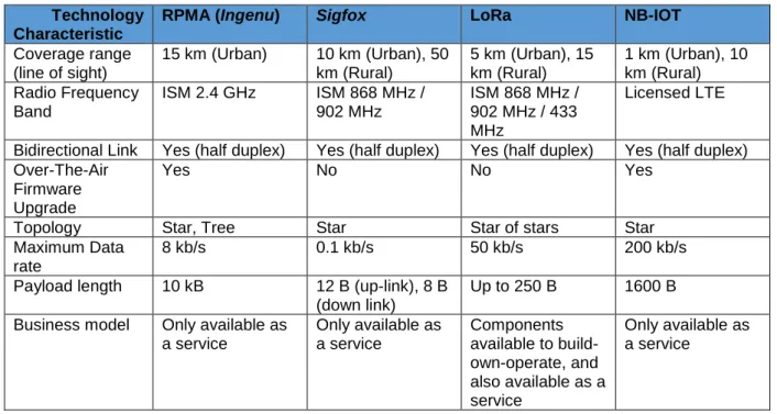
Other Wireless technologies
Sigfox
NB-IoT has a specific focus on enabling indoor coverage (which other LPWAN technologies can struggle with) and enabling large numbers of connected devices. NB-IoT technology is generally deployed "in-band" in the spectrum allocated to Long Term Evolution (LTE).
Introduction
Electromagnetic interference plays a vital role in the hardware layout of the boards, mainly due to the proximity of these modules to each other. These level shifters play an essential role in shifting the voltages to the required level/voltage of the microcontroller.
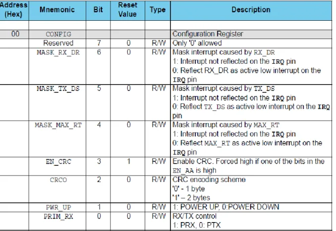
Implementing the Nrf24l01 Radio modules
Nrf24l01 Transmitter (TX Module
The libraries and functions related to the NRf24l01 radio module for the Nucleo board and the STM 32f4 discovery board are interchangeable. Some radio modules have a pinpack feature; this function can be "called" to configure the pins for the w module.
Implementing the LoRa Physical Layer devices
The Ethernet controller component of the research was essential in analyzing the data received from the LoRa radio module using the LoRa physical layer to some application that had to be used or visualized. The second SPI of the microcontroller, which is connected to the sx1278 LoRa radio module, acts as the receiver module for the LoRa message transmitted by the LoRa Tx module.
Visualising the LoRa Physical Layer
The payload LoRa packet received by the radio module after being demodulated is then written into a buffer of the microcontroller to access the enc28j60 Ethernet controller. Each of the LoRa receiver modules has its hard-coded Mac address, which means that these modules can parse data to the local network using their unique address, which also means that data from the different sources and locations can also be distinguished.
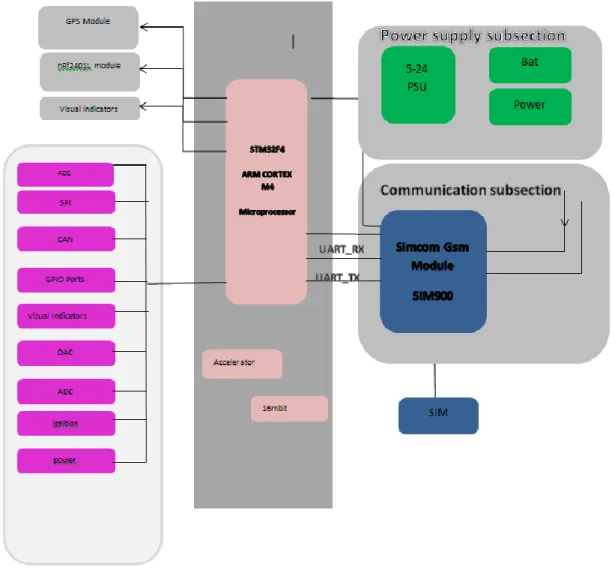
GSM Logger
- LoRa end Node Device
- LoRa WAN Gateway
- LoRa Gateway Bridge
- The LoRa Network Server(LNS)
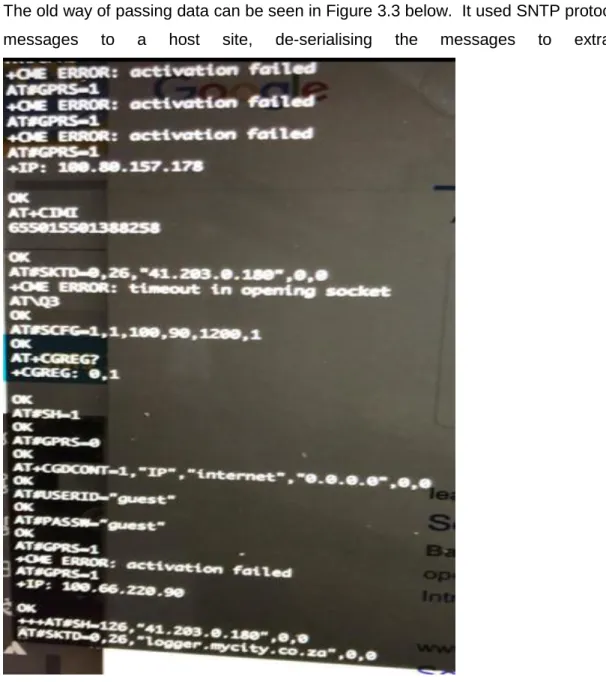
Figure 3.3 above shows a close-up view of the middle board, which is the motherboard of the GSM Logger. This research did not address the standard option as this would limit the learning of LoRa technology.
Gateway Data JSON Format
SQL Database as a Data source
Sensors send information to either PLCs or directly to the C# App Engine. This will be responsible for sending data to the CoCT device gateway in a CoCt packet format.
The device Gateway
The SOC-based SQL engine also proves the device-agnostic capabilities of the gateway to successfully log data to the same device gateway as the loggers. Both data sources use the same transport layer; however, the data layer handles "binary" data for the logs and.
Gateway Protocol Layers
Both aspects of these features are demonstrated by combining the new firmware and the device port. The device being requested is identified by the device ID, which is included as part of the.
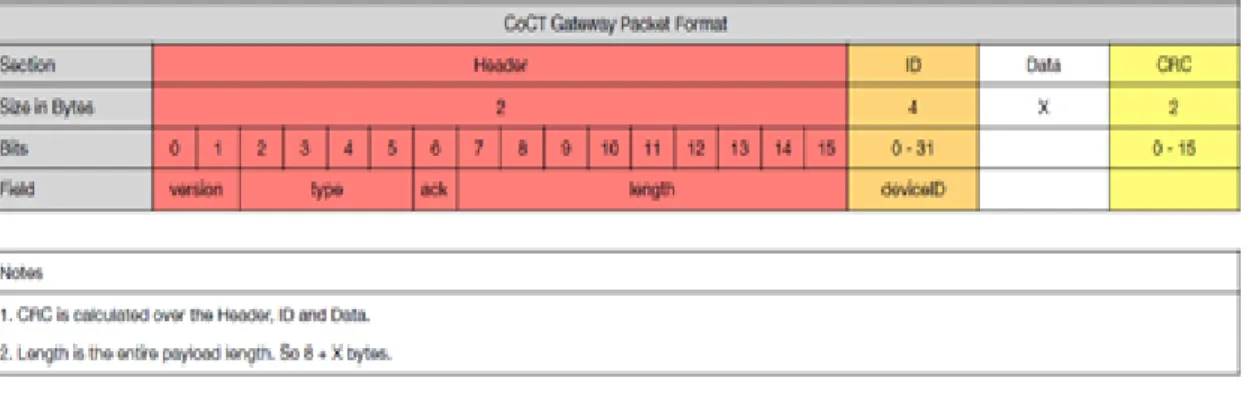
Data Layer
86 - It is important to note that CoCt packet format is the name given by this research to the packet format we developed and used as a standard for parsing data to the Device Gateway. With the advent of the 4th industrial revolution and the need to improve productivity levels, there is an increasing need for data analysis.
Introduction
This research presents the addition of a measuring device that was not installed as part of the original process control system. This data is parsed from this buffer to the payload of the LoRa radio module to be transmitted over the air.
The LoRa Receiver
Phase 2: Implementation of design using the B-L072Z development board
Only the 4-20 ma microe boards had to be linked to the board in the case of the transmitter node, and the ENC28J60 Ethernet module had to be linked to the receiver node.
The nrf24l01 Module
LoRa PHY
Nevertheless, it is enough to know that due to the Chirp Spread Spectrum (CSS) used, the power consumption does not depend on the content of the data. The payload of the standardized packet is fixed at 10 bytes, which is close to the proposed maximum of 12 bytes by TTN.
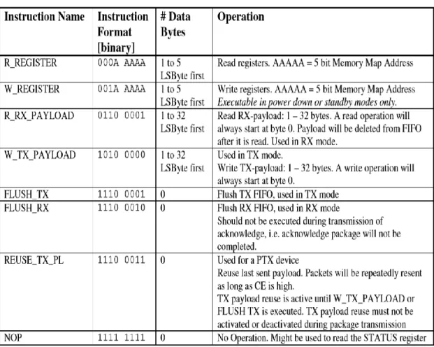
LoRa Packet Format
The LoRa radio module interface with the microcontroller is easily interfaced with the microcontroller with the SPI interface. There are also many open source libraries to adapt and use to interface the LoRa radio with the microcontroller.
IP Wrapper/Bridge
Testing and implementing The IP Bridge
There was a need for a packet manager or buffer to manage the packets arriving at the SCADA system. It was necessary to install and adapt a package manager to the LoRa/IP bridge to achieve this.
Comparing the NRF and the LoRa Node
106 - Before sending the UDP packets to the SCADA, it is necessary to have implemented a packet handler/buffer. The purpose of this packet handler/buffer is to parse only packets in a specific format to the SCADA, while discarding all non-compliant packets.
The complete data value Chain
Data Value Chain from LORA Node TX To Ignition SCADA Server
The LoRa Node Rx forwards the datagrams to a packet handler (data switch) using the packet data format. The data between LORA NODE TX and LoRa node RX is transmitted using propriety CSS.
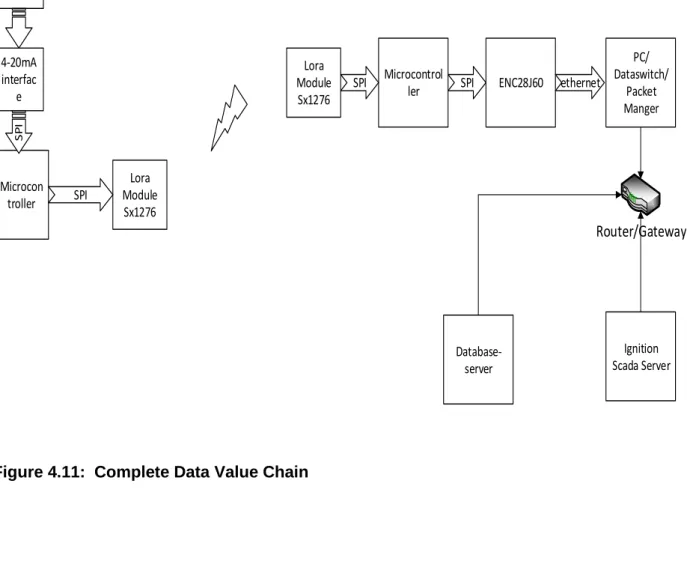
LoRa Node Rx/Data Switch Link
Each of the respective nodes is configured to act as either the LoRa transmitter module or the LoRa receiver module. There are many open source libraries for interfacing between specific microcontrollers and LoRa radio modules.
Data Switch – Ignition Master Link
The results of the analysis of the data will be accessible to Ignition slave stations (terminals). The Ignition SCADA system can also receive MQTT data via the MQTT broker installed on the ignition SCADA in the form of the MQTT transmission module.
INTRODUCTION
In the current context of the 4th industrial revolution and artificial intelligence, there is a growing need to obtain data from various data sources in a standard data format or data structure for use in Manufacturing Execution Systems (MES), Enterprise Resource Planning (ERP) or Web API. There are a few disabling factors in the South African context when investigating/testing the possibilities of transferring data across communication networks, particularly cellular networks, which block traffic on non-standard ports.
OVERVIEW OF PROTOCOLS
The protocol layer above UDP can be a protocol such as COAP in the case of 6LoWPAN. More and more processes are being automated in the modern industrial environment, thereby providing new possible data sources to high-level systems.
LORAWAN
117 - these technologies, it is clear that there must be some low-level implementation of the technology and some system integration into MES systems. Many developers and engineers chose the off-the-shelf and rapid development route, but these routes fail to deliver the full potential of the technology.
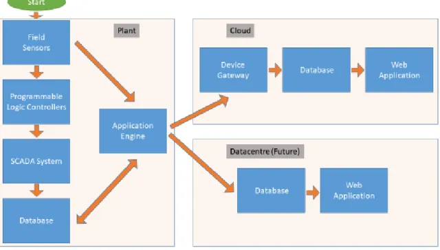
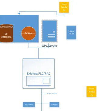
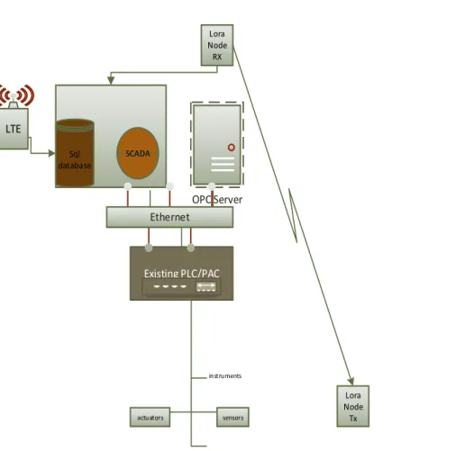
Present and Future architectures
Plant data
PLC/PAC systems have variables and labels already defined locally in these process-controlled systems; plants with local SCADA systems also have these tags defined in the SCADA systems. This data that is local to the plant can be collected and sent to the remote application server.
LoRa WAN IoT DEVICE Architecture
But this data is not processed beyond the plant, and there is a possibility to make this data available for MES / high-level API. In this study, we show how some data from these plants can be a data source for MES/API that can be translated into end-user/customer information to improve production KPIs and customer perspective.
Cost-Benefit of LoRa WAN option
The development process regarding interfaces of the LoRa radio module was carried out in a two-phase approach. The first stage was to connect an STM32F4 discovery board to the above two sensor variations and interface the sx1276 LoRa radio module.
Implementing the different Data sources
- LoRa WAN gateway as a Data source
- LTE/GSM Logger as a data source
- LOCAL Plant SQL Database as Data source
- Getting Data using OPC UA and MQTT from embedded OPC UA Data Source
This data is aggregated data that the C# application makes available to an LTE modem from broadcast to the device gateway in the defined CoCT Gateway packet format. The C# application will package the data according to the port package format seen in Table 1.
The Device Gateway
OPC UA
It is important to understand that OPC UA is an architecture and not a protocol on its own. OPC UA was initially intended or has its roots in the factory automation of large manufacturing plants within a LAN environment (Drahos et al., 2018).
COAP
RESULTS
136 - The above Figure 5.7 is a snapshot of a web page that was delivered showing visualization of devices from 2 wastewater treatment plants, namely Potsdam and Cape Flats wastewater treatment plants. The LTE logger, LoRa WAN and SQL data engines represent the device port's different types as a differentiator.
CONCLUSIONS
This chapter describes the results and findings after the successful completion/construction of the asset tracking device/data sources. The asset tracking appliance, once initialized, connects to the Gateway appliance, which for testing was a multi-socket application installed on a server.
LoRa Wan using Robustel R3000 Gateway
140 - The test should also consider that these LoRa endpoints will be installed underground in manholes where some industrial sensors are located.
Scope
Test equipment
Test methodology
Receiver Sensitivity
The basic premise of spread spectrum is that each bit of information is encoded as multiple chips. Semtech Corporation, 2013) The ratio between the bit and chip rate for LoRa modulation, respectively, is given by: Eqn. The performance of the LoRa modulation itself, forward error correction (FEC) techniques and the spread spectrum processing gain combine to allow significant SNR improvements.
Forward Error Correction
The table below shows some examples of SNR for conventional modulation formats and LoRa formats. Where SF is the spreading factor, SNR is the smallest ratio of the desired signal strength to the demodulated noise.
Test Results
The encoding rate changes as the distance from the port increases when the end node is moved linearly and proportionally away from the port. It is important to note that even when the SNR values were relatively poor, the coding rate.
Conclusion
Microcontrollers are also growing to be capable of much more than the old microcontrollers of the past. One of the other findings of this research is that in order to get the most out of the technology, and the technology must be adapted to get the full benefit, because not all technologies meet the end user's requirements like a glove.
Future Work
2018) “SA-OPC-UA: Introducing Semantics into OPC-UA Application Methods”, in IEEE International Conference on Automation Science and Engineering. 2013) “Keys to Embedded UA Server Development”, Matrikon Opc, p. 2019) “OPC UA vs. ROS, DDS, and MQTT: A Performance Assessment of Industry 4.0 Protocols,” in Proceedings of the IEEE International Conference on Industrial Technology.
Stage 1: de-serialize the Data: This section of the code handles packet verification and data integrity
RCC_ClkInitStruct.ClockType = RCC_CLOCKTYPE_HCLK|RCC_CLOCKTYPE_SYSCLK |RCC_CLOCKTYPE_PCLK1|RCC_CLOCKTYPE_PCLK2;.