User Agent
Submitted in fulfilment of the requirements of the degree
Masters in Computer Science at Rhodes University
Mosiuoa Tsietsi
March 10, 2008
The Session Initiation Protocol (SIP) has in recent years become a popular protocol for the ex- change of text, voice and video over IP networks. This thesis proposes the use of a class of structured peer to peer protocols - commonly known as Distributed Hash Tables (DHTs) - to pro- vide a SIP overlay with services such as end-point location management and message relay, in the absence of traditional, centralised resources such as SIP proxies and registrars. A peer-to-peer layer named OverCord, which allows the interaction with any specific DHT protocol via the use of appropriate plug-ins, was designed, implemented and tested. This layer was then incorporated into a SIP user agent distributed by NIST (National Institute of Standards and Technology, USA).
The modified user agent is capable of reliably establishing text, audio and video communication with similarly modified agents (peers) as well as conventional, centralized SIP overlays.
This thesis is dedicated to my family who have been with me through thick and thin, who believed in me when times were rough and tough. I am grateful for the support they gave me not just over the last two years, but all through my life. You mean a lot to me.
I would like to thank my supervisors, Alfredo Terzoli and George Wells for their tireless effort and patience when I needed it. This thesis is testimony to the quality of their stewardship and ability to motivate students to do their best, and dig just a little bit deeper.
I would also like to thank the staff members and students of the Department of Computer Science - thank you all.
Finally, thank you to my sponsors: Telkom SA, Business Connexion, Comverse, Verso Tech- nologies, THRIP, Stortech, Tellabs, Mars Technologies, Amatole Telecommunication Services, Bright Ideas 39 and the National Research Foundation.
Contents
1 Introduction 12
1.1 Usage scenarios for P2P SIP . . . 13
1.2 Services offered in a SIP network . . . 13
1.3 Decentralised protocols for P2P SIP . . . 14
1.4 Objectives . . . 15
1.5 Method . . . 16
1.5.1 Identification of open source DHT implementations . . . 16
1.5.2 Development of a generic interface . . . 16
1.5.3 Identification of an open source SIP user agent . . . 17
1.5.4 Interoperation with conventional SIP networks . . . 17
1.6 Scope of research . . . 17
1.7 Document overview . . . 18
2 Session Initiation Protocol 20 2.1 SIP entities . . . 21
2.1.1 User Agents . . . 21
2.1.2 Servers . . . 23
2.2 Registration . . . 24
2.3 Proxy service . . . 27
2.4 Establishment of multimedia sessions using SIP . . . 28 1
2.4.1 Audio and video sessions . . . 29
2.4.2 Instant messaging . . . 29
2.4.3 Presence . . . 30
2.5 Summary . . . 31
3 Peer-to-Peer Protocols 33 3.1 Classifying peer-to-peer systems . . . 34
3.2 Overlay networks . . . 35
3.2.1 Structured overlays . . . 35
3.2.2 Common APIs for structured overlays . . . 41
3.2.3 Unstructured overlays . . . 42
3.2.4 Comparing structured and unstructured protocols . . . 45
3.3 Summary . . . 48
4 Standardisation Efforts 49 4.1 Early work . . . 50
4.2 Concepts and terminology . . . 53
4.2.1 Peers and clients . . . 53
4.2.2 Protocol layering . . . 55
4.2.3 Location service . . . 56
4.2.4 Distributed database function . . . 57
4.2.5 Advanced services in the overlay . . . 58
4.3 P2P SIP implementations - SIPDHT . . . 59
4.4 Summary . . . 61
5 Designing the Peer-to-Peer layer 62 5.1 OverCord: A modular, layered framework . . . 63
5.1.1 Discovery layer . . . 63
5.1.2 Resource database . . . 64
5.1.3 Overlay repository . . . 65
5.1.4 The generic interface . . . 65
5.1.5 Plug-in layer . . . 66
5.1.6 Plug-in management . . . 68
5.2 Analysis of the OverCord framework . . . 69
5.2.1 Peers and clients . . . 69
5.2.2 Protocol layering . . . 70
5.2.3 Location service . . . 71
5.2.4 Data and service models . . . 71
5.2.5 Interoperating overlays . . . 72
5.3 Summary . . . 72
6 Implementing the Peer-to-Peer Layer 74 6.1 Overview . . . 75
6.2 Identification of overlay implementations . . . 75
6.3 DHT implementations . . . 76
6.3.1 OpenChord . . . 76
6.3.2 Bamboo DHT . . . 79
6.4 Development of plug-ins . . . 83
6.4.1 The OpenChord plug-in . . . 84
6.4.2 The Bamboo plug-in . . . 85
6.5 Plug-in management . . . 85
6.6 The discovery layer . . . 86
6.7 Interoperating peer-to-peer overlays . . . 88
6.8 Summary . . . 91
7 Incorporating OverCord into a SIP User Agent 92
7.1 Implications for conventional SIP user agents . . . 93
7.2 Java in IP telephony . . . 94
7.3 Designing applications with JAIN . . . 95
7.4 Choosing a user agent . . . 96
7.5 Modifying the JAIN SIP applet phone . . . 97
7.5.1 Configuration . . . 97
7.5.2 Registration . . . 99
7.5.3 Services . . . 99
7.6 Summary . . . 103
8 Interoperation with Conventional SIP Networks 104 8.1 Interoperating with conventional SIP . . . 105
8.2 Adding dynamic DNS support to OverCord . . . 110
8.2.1 DDNS clients . . . 110
8.2.2 A first attempt - Importing a DDNS client . . . 111
8.2.3 A second attempt - HTTP requests . . . 112
8.2.4 Node behaviour in a DDNS enabled environment . . . 113
8.2.5 Results and discussion . . . 114
8.2.6 Summary . . . 119
9 Conclusion 121 9.1 Achieved objectives . . . 122
9.1.1 Investigate peer-to-peer protocols for SIP . . . 122
9.1.2 Provide a framework for overlay pluggability . . . 122
9.1.3 Interoperation between heterogeneous overlays . . . 122
9.1.4 Interoperation with client-server SIP systems . . . 123
9.2 Contributions to P2P SIP research community . . . 123 9.3 Future work . . . 124 9.4 Summary . . . 125
References 126
A OverCord terminal outputs 136
A.1 Single node . . . 136 A.2 Multiple Nodes . . . 137 A.3 Heterogeneous overlays . . . 139
B OverCord Classes 140
B.1 Plugin Interface . . . 140 B.2 Multicast Discovery . . . 141 B.3 Plugin Manager . . . 149
C Accompanying CD-ROM 162
List of Figures
2.1 SIP - A layered protocol. Derived from [9]. . . 21
2.2 SIP user agent design showing how messages are sent, received and responded to. 23 2.3 The SIP registration process. . . 25
2.4 How the location service is used in establishing sessions. . . 26
2.5 Session establishment across two SIP domains. . . 28
2.6 A typical IM session between two users with an intermediary proxy. . . 30
2.7 A typical presence subscription between two users with an intermediary proxy. . 31
3.1 A classification of peer-to-peer systems. . . 34
3.2 A typical Chord ring. . . 37
3.3 An example of a Pastry node’s routing table. Adapted from [5]. . . 38
3.4 Example of 2-d [0,1] x [0,1] coordinate space with 5 nodes. Source: [6]. . . 40
3.5 Basic abstractions and APIs for structured protocols. Source: [39]. . . 41
3.6 Document location and retrieval in Gnutella. Adapted from [45]. . . 43
3.7 Super nodes and ordinary nodes in a KaZaA network. Source: [45]. . . 44
3.8 BitTorrent architecture. Source: [45]. . . 45
4.1 Block diagram of a P2P SIP node. Source: [52]. . . 51
4.2 (i) Node joining and (ii) session establishment in SOSIMPLE. Adapted from [54]. 52 4.3 An example XPP session between two users. Source: [70]. . . 60
6
5.1 The layered architecture of the OverCord framework. Adapted from [71]. . . 63
5.2 A possible construction of the discovery layer. . . 64
5.3 Plug-in layer and overlay layer with proprietary API. . . 67
6.1 Architecture of OpenChord. Source: [73]. . . 76
6.2 Summary of AsynChord and Chord interfaces. Derived from [73]. . . 78
6.3 A solution for interoperation of overlays. Adapted from: [53]. . . 89
7.1 WengoPhone client configuration frame. . . 93
7.2 Architecture of JAIN SIP. Source: [97]. . . 95
7.3 Message relay in OverCord. . . 100
7.4 Presence support across heterogeneous overlays with the JAIN Applet. . . 102
7.5 Instant messing session across heterogeneous overlays with the JAIN Applet. . . 103
8.1 A call from a peer-to-peer overlay to client-server system. Adapted from [101]. . 105
8.2 A call from a client-server system to a peer-to-peer overlay. Adapted from [101] . 107 8.3 A solution for interoperation of overlays using P2P SIP proxy. Adapted from [102] .108 8.4 Authentication dialog for DynDNS.com service. . . 113
8.5 Presence request from centralised user agent to peer-to-peer UA. . . 115
8.6 Presence status of peer-to-peer UA acquired by centralised UA. . . 116
8.7 Instant messaging session a client-server and peer-to-peer UA. . . 117
8.8 Presence status sharing supported by P2P SIP proxy. . . 118
8.9 Instant messaging session supported by P2P SIP proxy. . . 119
List of Tables
2.1 A subset of the SIP request messages in SIP. . . 22
2.2 SIP response codes. Derived from [9]. . . 22
2.3 SIP servers and their functions. . . 24
4.1 Examples of proposed P2P SIP Peer Protocols. . . 54
7.1 JAIN SIP stack properties. Derived from [97]. . . 98
8
Glossary Of Terms
AOR: Address of Record.
API: Application Programming Interface.
CAN: Content Addressable Network.
DDNS: Dynamic DNS.
DHCP: Dynamic Host Control Protocol.
DHT: Distributed Hash Table.
DNS: Domain Name System.
DNS NAPTR: Domain Name System Naming Authority Pointer.
DNS SRV: Domain Name System Service Record.
HTTP: HyperText Transfer Protocol.
IANA: Internet Assigned Numbers Authority.
IETF: Internet Engineering Task Force.
IM: Instant Messaging.
IP: Internet Protocol.
IPv4: Internet Protocol version 4.
IRIS: Infrastructure for Resilient Internet Systems.
ISP: Internet Service Provider.
9
JAIN: Java APIs for Intelligent Networks.
JCP: Java Community Process.
JSAP: JAIN SIP Applet Phone.
JSR: Java Specification Request.
KBR: Key Based Routing.
LAN: Local Area Network.
LDAP: Lightweight Directory Access Protocol.
MEGACO: Media Gateway Control Protocol.
NAT: Network Address Translator.
NIST: National Insititute of Science and Technology.
Node ID: Node Identifier.
P2P: Peer to Peer.
P2P SIP: Peer to Peer Session Initiation Protocol.
pCAN: Passive CAN.
PIDF: Portable Information Document Format.
Resource ID: Resource Identifier.
RFC: Request For Comments.
RTP: Realtime Transport Protocol.
RTSP: Realtime Streaming Protocol.
SDP: Session Description Protocol.
SEDA: Sandstorm Event Driven Architecture.
SER: Sip Express Router.
SIP: Session Initiation Protocol.
TU: Transaction User.
UA: User Agent.
UAC: User Agent Client.
UAS: User Agent Server.
URI: Uniform Resource Identifier.
URL: Uniform Resource Locator.
VoIP: Voice over Internet Protocol.
XPP: eXtensible Peer Protocol.
Chapter 1 Introduction
Begin at the beginning ... and go on till you come to the end: then stop.
- Lewis Carroll, Alice’s Adventures in Wonderland, 1865
The growth of the Internet, and IP networks in general, has seen improvements and increased diversity in the possible mediums of communication. Traditionally, technologies such as email and the web have been the predominant means of information exchange. At present, newer forms of communication such as Internet telephony, multimedia conferencing and multimedia streaming are fast becoming commonplace as services that can be delivered to users in realtime as opposed to the classical store and forward method.
The Session Initiation Protocol (SIP) is a popular choice for the delivery of realtime services over IP networks. In most settings, SIP is deployed using one or more central servers which perform dedicated tasks on behalf of users. While this setup has proven effective, there are many real-world scenarios where it would be beneficial or even necessary to provide the means of establishing point-to-point communication between endpoints themselves. The resulting archi- tecture is known as Peer-to-Peer SIP (P2P SIP). The standardisation of the protocols that will be used to enable P2P SIP is currently work in progress in the Internet Engineering Task Force (IETF), where a working group has been established. A summary of their contributions is the subject of chapter 4.
This thesis looks at using peer-to-peer protocols as tools for the creation of decentralised net- works upon which a telecommunication overlay based on SIP can be constructed. The SIP over- lay consists of SIP-enabled endpoints that perform traditional server functions in a cooperative manner. This chapter serves as an introduction to the area of study, starting with a non-exhaustive
12
enumeration of the possible usage scenarios for decentralised communications, followed by an account of the services that must be provided by a decentralised SIP network. The class of peer- to-peer protocols that were selected to achieve this purpose is presented, followed by an outline of the objectives of the research. Finally, this chapter details the steps that led to the development of a decentralised framework for P2P SIP and gives the scope of the project.
1.1 Usage scenarios for P2P SIP
The IETF working group on P2P SIP released an Internet draft that classified the possible sce- narios for the usage of P2P SIP [1] into four main groupings, which are described below:
1. Global Internet Environment - P2P SIP can be used as a means of creating a global, openly available VOIP network with no (or little) central administration.
2. Security Demanding Environments - For security or privacy reasons, users or organisations may not want their data to traverse the infrastructure of service providers or may not be allowed to use the infrastructure, thus making a peer-to-peer solution more attractive.
3. Environments with Limited Internet Connectivity and Infrastructure - For environments such as the developing world, ad-hoc and ephemeral groups or disaster situations, where Internet connectivity may not be present or may be unreliable, a local and inexpensive self-configuring solution would be necessary.
4. Managed Private Network Environments - For the purpose of cost reduction or improved scalability of VOIP systems, organisations may decide to complement their client-server based systems with a peer-to-peer solution.
1.2 Services offered in a SIP network
If one considers what is needed in order for a simple conversation between two SIP endpoints (called user agents) to occur, it is possible to understand how the centralised theme permeates SIP networks. Firstly, each user agent must initiate the registration process which ultimately provides the network with information that allows it to make an association between the user’s identity and the user’s locality. This often means that each user agent must be pre-configured to interact with
a specific SIP server, typically a SIP proxy, which knows the location of another server called a registrar, which authenticates them. The registrar, upon receipt of a registration request, will compare the credentials supplied by the clients with those stored in a central database (which can be hosted by the registrar itself or by another server). The database is called a ”location service” because it associates a user’s SIP address with a locality record which points to the actual network location of the user’s device. The SIP proxy server assists in facilitating the exchange of SIP messages (a process called signalling) between the endpoints. Once the endpoints are successfully registered and the signalling process has succeeded, then media streams can be established in both directions.
The processes described above are underpinned by two main activities. Firstly, there is the administrative effort which goes into running a SIP network. This is reflected in the need for the configuration of both SIP clients and servers, and the setup and maintenance of a central database system. Secondly, SIP relies on a naming service based on domains which is usually provided by an implementation of the Domain Name System (DNS).
It is possible to enumerate the services provided by a SIP network. These services are not dis- carded by a peer-to-peer solution, but must be implemented in a distributed manner. These services are:
Proxy A service which is able to handle requests on the behalf of others.
Registration A service which accepts registration requests from user agents.
Location Service A database of locality mappings crucial for session establishment.
Administration It must be possible to perform actions such as create new networks and add new users.
1.3 Decentralised protocols for P2P SIP
In order to perform the services listed above in a decentralised manner, a logical choice is to borrow from the realm of peer-to-peer protocols. By nature, peer-to-peer systems are able to pool the bandwidth, processing power and storage capabilities of its constituent nodes. In addition, it is typical for these systems to be able to sustain and coordinate themselves with little or no external supervision, hence their popularity in recent years as evidenced by such systems as KaZaA [2] and BitTorrent [3].
Peer-to-peer protocols can be roughly divided into two classes, structured and unstructured.
Structured protocols place certain constraints on the node graph so that searches for resources stored in the network follow a deterministic path. Unstructured protocols impose no such con- straints, allowing nodes to be organised in a random graph where there are random joining pro- cesses and neighbour selection algorithms.
It would seem that interest has been growing in a class of structured peer-to-peer protocols com- monly known as Distributed Hash Tables (DHTs). The name is derived from their ability to provide a decentralised key-value based lookup service, which is supported by a structured set of node links. In this thesis, the term DHT is used in reference to both the protocols as well as the hash table abstraction they provide.
DHTs have been identified by the research community working on protocols for P2P SIP as a possible platform for providing the distributed location service for SIP. However, when the work towards this thesis commenced, it was not clear that DHTs would become part of the standard.
1.4 Objectives
DHTs may satisfy the requirements presented in section 1.2, but there are a number of imple- mentation challenges with their use. Firstly, there are many DHT protocols in existence today [4, 5, 6, 7]. It would be beneficial to provide the means for any DHT to be used so that a P2P SIP client does not have to be molded to use a single, must-implement DHT. Secondly, while all DHTs provide a similar basic lookup service, there are some differences in how they provide this service and in the way they expect to interact with the applications which make use of them.
Given these points, the overall objectives presented in this thesis are:
1. To investigate the use of peer-to-peer protocols, and in particular DHTs, for use with SIP.
2. To provide a DHT-agnostic method for many DHT modules to be plugged into a single P2P SIP system.
3. To investigate the possibility of providing interoperation between heterogeneous overlays.
4. To provide a solution for decentralised overlays to interoperate with conventional SIP net- works.
1.5 Method
An applied experimental approach was followed in this research, that involved the development of a peer-to-peer framework followed by its incorporation into a SIP user agent. The framework was named OverCord. The name consists has two distinct parts: over and cord, which refer to the system’s ability to support many types of overlays in a similar way to an electrical extension cord that supports many devices.
1.5.1 Identification of open source DHT implementations
An investigation into existing DHT implementations revealed that there is much activity in this area, and it was possible to access stable, open source code largely in C/C++ and Java. This investigation was done in parallel with the one described in section 1.5.3 below, which covers the identification of an open source SIP user agent. This led to the selection of the Java based implementations, from which two DHTs called OpenChord and Bamboo were chosen. The two DHTs are discussed in detail in section 6.3.1 and section 6.3.2 respectively.
1.5.2 Development of a generic interface
DHTs commonly export an application programming interface (API) - a software interface com- posed of functions - through which an external application can control it. The functions necessary for P2P SIP would include those for message routing as well as for the lookup, insertion, update and removal of resources from a location service. To achieve the objective of DHT pluggability, given that each DHT exposes a different API, it would be beneficial to create a single, generic interface which could be used across all DHTs that the application has access to. This means that a middleware layer needs to be implemented that is able to translate the generic API methods to the proprietary APIs of each DHT. This middleware layer was implemented via the creation of software ”wrappers” which perform the translation. In OverCord, these wrappers are called plug-ins. After the two DHTs had been selected, plug-ins were developed for each one. The generic interface was tested and found to be successful in interacting with the plug-ins.
1.5.3 Identification of an open source SIP user agent
Since the objective of the research was to construct a peer-to-peer layer for currently existing SIP user agents, it was necessary to identify an open source application into which such a layer could be inserted. The investigation identified the JAIN SIP Applet Phone [8] which uses a Java based SIP stack known as JAIN (Java APIs for Intelligent Networks). The result of the incorporation was tested and proved successful.
1.5.4 Interoperation with conventional SIP networks
Having produced a peer-to-peer layer for SIP and tested its ability to support communication across heterogeneous overlays, it seemed interesting to try to provide similar support for interop- erating with conventional SIP networks. It became evident that an asymmetry existed: it would be more difficult to provide communication from centralised networks to decentralised networks than the other way around. The difficulty arises from the fact that most centralised networks rely on DNS to calculate the next hop destination for messages. Though it is possible to create DNS resource records for elements in peer-to-peer overlays, conventional DNS is unsuitable for peer-to-peer environments due to the high churn rates, which would require unusually frequent DNS record updates. Dynamic DNS (DDNS) was identified as an appropriate alternative, since it supports dynamic updates and low TTL (time-to-live) periods for resource records. A node in the overlay would thus be able to play the role of an ephemeral proxy for incoming and outgoing messages.
1.6 Scope of research
The main focus of the research is to investigate the requirements of a decentralised framework for SIP and to produce a prototype application that shows how this framework can be used to support realtime communication using SIP.
The scope of the research explicitly excludes the following:
1. Proving why P2P SIP may be better than centralised SIP.
2. Making conclusions about which class of peer-to-peer protocols is best suited for P2P SIP.
3. Considerations for enabling communications in environments where some or all of the endpoints are behind Network Address Translators (NATs).
4. Security concerns which include issues such as the secure allocation of unique user cre- dentials, user authentication and preventing malicious attacks on either stored data or the routing infrastructure of the overlay.
1.7 Document overview
The rest of the thesis is organised as follows:
Chapter 2 This chapter examines the SIP protocol within the limits of what is necessary to understand the rest of the thesis. It defines the different roles and message types that the protocol uses and explains how SIP supports multimedia services. The chapter uses the description of SIP to make the point that SIP is naturally supportive of distributing server roles among overlay nodes. The next chapter explores the different peer-to-peer protocols that can help perform this decentralisation.
Chapter 3 This chapter gives a taxonomy of peer-to-peer protocols, as an initial step towards identifying an appropriate platform for decentralising SIP. This chapter divides peer- to-peer protocols into two classes: structured and unstructured. Examples of each class are given in order to identify common characteristics and lastly, a compari- son between the two is made which evaluates the suitability of each to provide the services needed for SIP.
Chapter 4 This chapter summarises the protocol proposals and analyses the prototype imple- mentations of the recently established P2P SIP working group in the IETF. Some of the early work is described as well as the newer and more mature concepts that are likely to feature in the final standard.
Chapter 5 This chapter details the design of a peer-to-peer architecture called OverCord. The design is multi-layered, modular and supports the plugging in of new modules. The architecture can be used to construct user agents for SIP, but due to the separation be- tween application and service, it is anticipated that it can be used for other purposes beyond P2P SIP.
Chapter 6 This chapter describes a possible implementation of the OverCord system. The implementation is based on implementations of DHTs and shows how OverCord, in isolation from any service application, can be used to create decentralised overlays.
Chapter 7 This chapter describes the process of incorporating OverCord into a Java based SIP client called the JAIN SIP Applet Phone. The different options that were avail- able when choosing an appropriate environment for performing this incorporation, namely the SIP stack and client application, are outlined and justification is given for the successful candidates. The steps that were followed in performing the incorpo- ration are detailed, giving insight into the different portions of the client that needed to be reworked in order to perform the integration. The results of test are given at the end of the chapter which show SIP clients communicating not only within the same overlay, but with heterogeneous overlays.
Chapter 8 This chapter deals with the interoperation of overlays based on peer-to-peer proto- cols and conventional SIP networks, based on SIP servers and DNS. Possible meth- ods to achieve this are given and critiqued, followed by a discussion on the method that was employed in this research. The proposed solution is based on dynamic updates to DNS records which are more suitable for chaotic, decentralised environ- ments characterised by high churn rates.
Chapter 9 This chapter concludes the thesis, summarising the work done and the significance of the contribution towards the development of P2P SIP. Some comments on the opportunities for future work on the design and implementation are also given.
Chapter 2
Session Initiation Protocol
Our life is frittered away by detail ... Simplify, simplify.
- Henry David Thoreau, Walden, 1854
The Session Initiation Protocol (SIP) is an application layer protocol standardised by the Internet Engineering Task Force (IETF) which is used for creating, modifying and terminating sessions such as Voice over Internet Protocol (VoIP) and multimedia conferences [9]. Intended as a mem- ber of a larger multimedia framework, SIP was designed with the native ability to incorporate a range of IETF protocols such as Realtime Transport Protocol (RTP) [10], Realtime Streaming Protocol (RTSP) [11] and Media Gateway Control Protocol (MEGACO) [12].
In most deployment environments, a SIP network is supported by a server, or servers, which perform certain functions for the network. Clients are largely dependent on the servers, without which they would have difficulty communicating with, and locating each other. Despite this centralised viewpoint of SIP, many aspects of the protocol are essentially peer-to-peer, such as audio and video conversations between SIP clients, which do not normally involve the server.
By definition, SIP also fosters an abstract association between entity and function, providing an opportunity for services to be provided in a distributed and cooperative manner. This chapter does not give a thorough overview of SIP, for which the reader may refer to the protocol standard [9]
or other literature such as [13, 14]. However, this chapter does define terminology and concepts required to understand the identity and function of SIP entities, and the multimedia services they are able to support. In addition, it highlights the inherent opportunities that SIP provides for decentralising services without violating the syntax or semantics of the protocol, by using techniques to distribute the services over a number of participating endpoints.
20
2.1 SIP entities
SIP entities are divided into two groups, SIP endpoints (called user agents) and SIP servers, which are described in the next two sections.
2.1.1 User Agents
SIP, like the Internet Protocol (IP) upon which it is based [15, 16], is itself a layered protocol consisting of layers that define the behaviour of all SIP entities. Its architecture is depicted in Figure 2.1. The lowest layer defines the message structure and grammar of the protocol. The next layer is the transport layer, which defines how an entity sends requests and receives responses as a client, and how it receives requests and sends responses as a server. The transaction layer is built above the transport layer and defines how an entity handles a SIP transaction. In SIP, a transaction encompasses a request sent by a client and all subsequent responses to that request by a server. The topmost layer is the transaction user (TU) layer. This layer ties all the lower layers together in that it is responsible for creating requests through the transaction layer. All SIP entities conform to this model, except for the stateless SIP proxy discussed in section 2.3, which only differs in that it does not have a TU layer.
Figure 2.1: SIP - A layered protocol. Derived from [9].
Endpoints in SIP are known as user agents (UAs). A UA is an example of a TU and is host to two discrete components, a User Agent Client (UAC) and a User Agent Server (UAS). The UAC
is capable of creating requests and a UAS is capable of generating responses to requests. Some common SIP request messages are given in Table 2.1. Table 2.2 defines the classes of response codes that are generated to SIP requests.
Message Name Meaning
REGISTER Used by a user agent to notify the SIP network of it current Contact URI and the URI that should have requests routed to the Contact.
INVITE Used to establish media sessions between user agents.
MESSAGE Used to carry instant message content.
PUBLISH Used to publish event state and distribute it to interested parties.
SUBSCRIBE Used to request asynchronous notification of an event or set of events at a later time.
NOTIFY Used to notify a SIP entity that an event which has been requested by an earlier SUBSCRIBE method has occurred. It may also provide further details about the event.
OPTIONS Used to indicate user agent capabilities.
CANCEL Used for canceling a pending request.
ACK Used to indicate acknowledgment of the reception of a message.
BYE Used to terminate a session.
Table 2.1: A subset of the SIP request messages in SIP.
Class Description Action
1xx Informational Also known as provisional - the server is performing an action but does not yet have a definitive response.
2xx Success Request was successful.
3xx Redirection Gives information about the user’s new location, or about alternative servers that might be able to satisfy the call.
4xx Client error The client should not retry the request without modification (for example, adding appropriate authorisation). However, the request may succeed at a different server.
5xx Server failure The server has erred.
6xx Global failure The server has definitive information about a particular user, not just the particular instance indicated in the Request URI.
Table 2.2: SIP response codes. Derived from [9].
Figure 2.2 shows how a UA consists of a UAC and a UAS. When creating a request, the UAC creates a client transaction, and sends it to a UAS, which creates a server transaction to handle the request. An important concept related to user agents and message exchange is a dialog. This is a peer-to-peer relationship between two UAs that persists for some time. It is useful for properly
handling the sending and receiving of messages between two entities that intend to communicate.
Of the request messages listed in Table 2.1, only the INVITE and SUBSCRIBE messages create a dialog. Other messages are exchanged within a dialog.
Figure 2.2: SIP user agent design showing how messages are sent, received and responded to.
2.1.2 Servers
SIP defines three main types of servers, namely the proxy, registrar and the redirect servers, whose functions are given in Table 2.3. Some of the terms given in these definitions are explained in the next three sections. SIP servers, like UAs, are also TUs that create server transactions to handle client requests. For example, a registrar can be defined as any UAS that creates a server transaction for registration requests it receives from a client transaction. UAs, proxies, registrars and redirect servers all have cores that differentiate one from the other, but those cores are TUs that can respond to SIP messages in similar ways.
Since SIP servers, like all SIP entities, are defined as logical elements, servers can be co-located on the same hardware. This means that from an implementation point of view, a registrar can be co-located with a proxy, or a redirect server with a registrar. In fact, a SIP server can be defined as such on a purely transaction by transaction basis [9].
Server name Function
Registrar A server that accepts REGISTER requests and places the information it receives in those requests into the location service for the domain it handles
Proxy An intermediary entity that acts as both a client and a server for the purpose of making requests on behalf of other clients
Redirect A user agent server that generates 3xx responses to requests it receives, directing the client to contact an alternate set of URIs
Table 2.3: SIP servers and their functions.
2.2 Registration
Human users of SIP networks use some kind of SIP UA device such as a software phone (called a softphone), hardware phone (called a hardphone) or a videophone, to communicate. Such a user, say named Mosiuoa, possesses a unique SIP address such as sip:[email protected], which is known as a SIP Address of Record (AOR). Mosiuoa uses this address to identify himself to the rest of the world. This AOR is structured in a similar way to an email address, where the mosiuoa portion of the AOR identifies the user’s name, and the ru.ac.za portion identifies the domain in which he belongs.
In order to participate in the domain and begin to interact with others, Mosiuoa’s UA needs to formally join the ru.ac.za domain. In SIP, this process is known as registration, and is formally described as the process through which a user associates their AOR with another form of address known as a contact address or contact URI, which more accurately informs the network of where this user can be reached. For example, the AOR sip:[email protected] may be associated with the contact address sip:[email protected]:5060, which indicates the IP address and lis- tening port of Mosiuoa’s SIP UA. This process of registration is accomplished by the creation of a SIP REGISTER message (see Table 2.1), which the UAC sends to a UAS which can handle the request. A user may associate a single AOR with multiple contact addresses so that messages can be sent to various SIP devices that the user owns. The process of registration is depicted in Figure 2.3.
Figure 2.3: The SIP registration process.
In order for a user to join a SIP domain, the UAC must know beforehand the destination to which to send the REGISTER message. There are several methods available to the UAC to do this, which are discussed in [9]. These are:
Manual Configuration A UA can be manually configured by an administrator or experienced user, or may have built-in knowledge of the location to send requests.
Default Domain If a UA is not manually configured, it may choose to send the request to the host part of its AOR, such as sip:ru.ac.za for a UA on the domain ru.ac.za.
Multicast Registration A UA can send the request to the multicast address sip.mcast.net, which is known as the all SIP servers address (224.0.1.75 for IPv4), which will be responded to appropriately by a UAS listening on this multicast address.
When the registrar receives the registration request, it performs certain administrative checks on it. For example, the registrar must check that the host portion of the AOR of the originating UA falls in its administrative domain. A registrar may also challenge unauthenticated requests as shown in Figure 2.3. If all requirements have been met, the registrar adds the binding between the AOR and the contact address into an abstract data service called the location service. The location
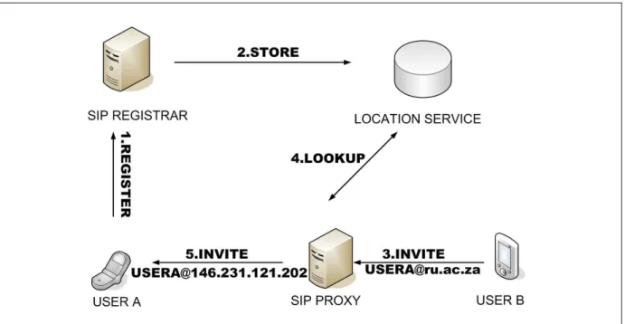
service stores all the bindings on the behalf of the network and exposes these to other servers such as the redirect server. It can be implemented in various ways since the protocol specification does not standardise its structure or the exact format of the resource records it contains. Implementers of location services have traditionally used technologies such as relational databases and the Lightweight Directory Access Protocol (LDAP) [17]. Figure 2.4 shows how the location service is populated and how it assists servers such as proxies to perform their functions. The behaviour of the proxy is described in detail in the next section.
Figure 2.4: How the location service is used in establishing sessions.
The use of the REGISTER message is not limited to facilitating the process of adding bindings to the location service, but can also be used to modify or remove them. Each binding in the location service has an associated expiry interval, after which the binding will be automatically removed.
This interval is stipulated in the class 2XX OK response sent back to the client after a successful registration. It is the responsibility of the client to refresh bindings before the record expires, which it accomplishes by sending an appropriate REGISTER message back to the registrar. A client may also remove bindings by modifying the Expires header in the REGISTER message by setting it to 0, which results in the removal of the binding from the location service.
2.3 Proxy service
Once a user has successfully registered with the registrar, that user is free to establish sessions with other users in the network. These sessions are established through the exchange of messages between endpoints, which in telephony is known as signalling. To aid in the routing of messages between endpoints, SIP defines the role of an entity called a SIP proxy. SIP distinguishes between a stateful and a stateless proxy. According to [9], a stateful proxy maintains the client or server transaction states of a request, and as such is alternatively known as a transaction stateful proxy.
A stateless proxy does not maintain such state, and as such, simply forwards every request it receives downstream, and every response it receives upstream. Apart from message relay, SIP proxies can also perform other functions such as:
Authentication The proxy can challenge user requests to make sure they are authorised to use the service.
Loop Detection Messages could sometimes loop between a set of proxies forever, and a proxy can perform actions to prevent this from occuring.
Forking A proxy can route messages to several destinations at which a user has indicated avail- ability.
Record Routing A proxy can request to remain in the signalling path in subsequent messages in a dialog.
Administrative As flexible elements in a SIP network, policies based on traffic load, security and user preferences can be taken into account when performing message routing.
An element intending to proxy a request it has received from a UAC must perform four key tasks.
Firstly, it validates the request, which includes checking for correct message syntax. Secondly, it inspects the destination of the message, which is contained in a SIP header called the Request URI. Thirdly, it determines the target, or targets of the message. Lastly, it forwards the message to the target SIP entity. Needless to say, since a stateful proxy handles requests on a transaction basis, it can handle functions such as retransmissions when performing these steps.
This discussion on the role of the proxy completes the description of Figure 2.4 by showing how, after the process of registration has succeeded, messages from other users can be proxied to the user’s location for the establishment of sessions. Session establishment is discussed in greater detail in the next section.
2.4 Establishment of multimedia sessions using SIP
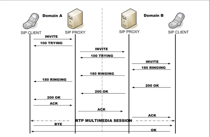
SIP is able to support the establishment of a wide range of multimedia sessions through signalling mechanisms. Figure 2.5 shows the sequence of messages that are exchanged in order to setup and terminate a multimedia session between two UAs in separate domains. The session is established through the use of the INVITE message, which was defined in Table 2.1.
Figure 2.5: Session establishment across two SIP domains.
The UA generating the INVITE can use the methods described in section 2.2 to locate the SIP proxy in its own domain. When both the sender UA and the receiver UA are in the same domain, the records in the location service can inform the proxy of domain A in Figure 2.5 where next to send the message, called the next hop. In the non-trivial case where the sender and receiver are not in the same domain, the proxy on the originating side must determine the next hop address, port and transport protocol which it must use to route the message. Local policies may be in place that determine the correct behaviour in this instance, such as reading values from a database or sending the message to a default server, as suggested in [9]. However, the generally used method
is that the proxy will use DNS procedures to retrieve the appropriate SRV and NAPTR records of the SIP proxy serving the foreign domain, as indicated by the domain part of the Request URI in the SIP request [18]. Using this technique, as shown in Figure 2.5, the INVITE message can be routed to the proxy in domain B. There, the location service informs the proxy of the location, or locations of the intended user. The proxy then uses the contact address of the proxy in domain A (which it has appended in a SIP header called a Via header in the original INVITE) to re-route subsequent messages back to domain A.
2.4.1 Audio and video sessions
Figure 2.5 shows that once the three-way handshake of INVITE-OK-ACK has completed, mul- timedia traffic between those endpoints proceeds in a peer-to-peer fashion. Central to the provi- sioning of these services is the use of the Session Description Protocol (SDP) [19] which is used to describe sessions between participants including media details, transport protocols and other forms of metadata. SDP can be used, for example, as as basis for the negotiation of media codecs between users in an audio or video session.
In Figure 2.5, at the point where the user agent in domain B sends a 200 OK response to the SIP request, a dialog is created (see section 2.1.1). Using Figure 2.5 above as an example, after the session has been established and a dialog has been created, one of the SIP UAs may choose to modify the properties of the session in some way, such as using a different audio or video codec.
A new INVITE message called a re-invite is generated and sent, which does not need to traverse the proxies since the signalling can be accomplished through the use of the already established dialog, and the UAs can negotiate the new properties of the session themselves.
2.4.2 Instant messaging
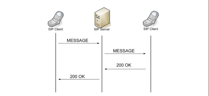
The introduction of the MESSAGE request added the ability to convey text information in near- realtime between users. This form of communication is known as instant messaging, or IM.
Figure 2.6 shows how messages would be exchanged between two users in an IM session.
Figure 2.6: A typical IM session between two users with an intermediary proxy.
2.4.3 Presence
IM is a useful tool for communicating, but the initiator of an IM request, unlike an audio or video session, is unable to determine if the user at the other end is able to respond to the IM request or not. Presence refers to the ability of a user to communicate their willingness or availability to interact with others. Presence is supported in SIP with the SUBSCRIBE and NOTIFY request messages [20].
An entity (called a watcher) wishing to obtain a lease for presence updates of another entity (called a notifier) uses the SUBSCRIBE message. The notifier responds with an SIP 200 OK response followed by a NOTIFY, which contains the status information in the body of the mes- sage. A notifier will resend NOTIFY messages every time its presence status changes, as well as sending updates at regular intervals. Watchers are responsible for refreshing leases on pres- ence updates, which is also facilitated by the SUBSCRIBE message. An example of a successful presence subscription and notification is given in Figure 2.7.
Figure 2.7: A typical presence subscription between two users with an intermediary proxy.
Subsequent to [20] which defines the SUBSCRIBE and NOTIFY messages, a further extension to SIP was defined with the introduction of the PUBLISH method [21]. Use of this method is meant for delivery to a special UAS which is responsible for collecting state and distributing it to subscribers. In this manner, a notifier can publish state to an event compositor and valid watchers can obtain the notifications from the compositor.
2.5 Summary
SIP is an application layer protocol which can be used to create multimedia sessions such as audio, video and instant messaging, as well as support presence subscription and advertisement.
SIP defines a number of abstract entities that provide services to the SIP network. However, it is evident from the protocol specification that there is no rigid binding between a service and the identity of the entity providing that service, since almost all SIP entities but one, have the ability to both initiate and respond to messages that create these sessions as TUs. Many facets of realtime communication using SIP are essentially peer-to-peer, and support the transfer of information without intermediate and centralised elements. This includes the peer-to-peer RTP sessions that are established subsequent to session establishment, and the dialogs that are created
between user agents. Decentralising SIP means decentralising the roles of the proxy, registrar and redirect server, and the implementation of a decentralised location service. The resulting design is known as P2P SIP. The next chapter looks at some of the peer-to-peer protocols that may assist in performing this decentralisation.
Chapter 3
Peer-to-Peer Protocols
All animals are equal.
- Animal Farm, George Orwell, 1945
Peer-to-peer networking is a concept that has risen in popularity in recent times, as evidenced by the large collection of computer applications that are based on peer-to-peer techniques and support services such as file sharing, instant messaging and peercasting. The power behind peer-to-peer networking lies in its ability to pool the bandwidth, processing power and storage capacities of a number of participating hosts that are spread over a potentially large geographic area. This can be achieved in a self-sustaining and self-organising manner, without any or much centralised control or intervention.
The purpose of this chapter is to give a brief overview of peer-to-peer systems as an initial step towards selecting an appropriate platform for decentralising SIP. A classification of peer-to-peer systems is given, after which two classes of peer-to-peer systems are compared, highlighting the advantages and disadvantages of each for the purposes of P2P SIP.
33
3.1 Classifying peer-to-peer systems
There are numerous definitions for the term peer-to-peer systems. A detailed definition is given in [22]:
peer-to-peer systems are distributed systems consisting of interconnected nodes able to self-organize into network topologies with the purpose of sharing resources such as content, CPU cycles, storage and bandwidth, capable of adapting to failures and accommodating transient populations of nodes while maintaining acceptable connectivity and performance, without requiring the intermediation or support of a global centralized server or authority.
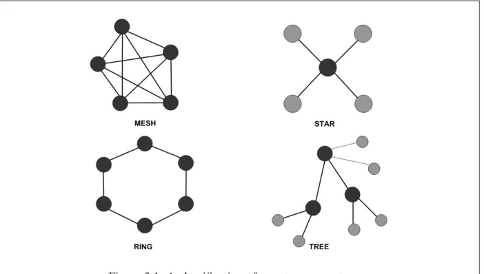
In the definition above, network topologies refer to the arrangement of nodes in a network and the connections between them. Four popular network topologies are shown in Figure 3.1, followed by a brief description of each.
Figure 3.1: A classification of peer-to-peer systems.
Mesh Where all nodes in the network are connected to all other nodes in the network.
Star Where all nodes in the network are connected to one central node such as a network hub.
Ring Where the nodes in the network are arranged in a circular fashion.
Tree Where sets of nodes are connected to one central node in a hierarchical pattern, and in turn, the central nodes are connected to each other.
It is often possible to layer networks over others. Such networks are known as overlay networks or simply overlays, of which the Internet is a prime example as it is layered over other telecom- munication networks. The next section discusses the different types of overlays that exist and some of the protocols that are used to create them.
3.2 Overlay networks
There are many different possible ways to classify overlays, which is due to the sheer number of protocols in existence today and the rate at which new ones are being invented. However, a popular classification of overlays distinguishes between structured and unstructured overlays.
3.2.1 Structured overlays
Structured overlays are efficient at mapping a key to a node [23]. Usually, cryptographic func- tions are used to generate node identifiers (or node IDs) for nodes in the overlay such that ev- ery node is identified by a unique identifier. Nodes in a structured overlay can host resources, whereby each resource is identified by a resource identifier (or resource ID), which is in the same address space as the node IDs. In many contexts, the resource ID is also known as a key. It is this relationship between the two types of identifiers that allows structured overlays to make an association between a resource and the node that hosts that resource. The node with the identifier whose value is nearest to the value of the resource identifier is selected to host the resource. The hosting of resources is defined in an abstract way such that the incumbent node may physically store the resource (such as a file) or simply have a pointer to where that resource can be found (such as a URI).
Node IDs are used to establish logical relationships between nodes with identifiers that are near each other by some protocol-specific definition of nearness. Nodes in structured overlays keep track of a limited number of neighbours through the use of a routing table, which is typically of sizelog(N), whereN is the total number of nodes in the network. These routing tables are consulted when the overlay handles a query for an identifier. A query is passed from node to
node aided by these routing tables. At each hop, the query is routed nearer to the target until the node to which the query maps is obtained. Due to their ability to efficiently map keys to nodes, these protocols are often called Distributed Hash Tables (DHTs). There are many DHTs in existence and three popular ones are described in the next three sections.
3.2.1.1 CHORD
Chord is arguably the best known DHT and was developed at the Massachusetts Institute of Technology (MIT) in the United States [4]. At its core, Chord is a simple lookup substrate which maps a key to a node ID. A Chord overlay has a ring topology where nodes are assigned successive node IDs which are generated by using a variant of the consistent hashing function [24]. It is sufficient for a Chord node to maintain the < nodeID, IP address > tuple of its immediate successor in the ring to ensure the correctness of the lookup algorithm. However in addition to this, to improve the performance of the algorithms, a Chord node can keep record of (at most)m neighbour nodes in a routing table called a finger table, wherem is the number of bits in a node ID.
A noden with anm-bit identifier builds up a finger table of successor nodes using the formula s = successor(n + 2i-1), where 1 ≤ i ≤ m and all arithmetic is done modulo 2m. The ith finger table entry at node n contains the identity of the first nodes that succeeds n by at least 2i-1 on the identifier circle. A Chord finger table entry contains a mapping between a node ID and the corresponding IP address and port number of the successor node. The lookup(key) algorithm proceeds either iteratively or recursively, where the query is propagated through the overlay, at each step being routed to the node whose identifier has a numerical value equal to or closest tokey, until that node is found. This information allows successful lookups to be made inO(log(N))time in a Chord overlay ofN nodes.
Figure 3.2: A typical Chord ring.
Figure 3.2 depicts a Chord ring where only the nodes with identifiers 0, 1, 3 and 5 are online.
Nodes in the ring have three-bit identifiers (i.e. m = 3) and as such, there can only be up to eight nodes in the ring, each with up to three entries in its finger table. The IP addresses and port numbers have been omitted in the finger tables for simplicity. As an example, the node with identifier 1 stores the successors of nodes 2, 3 and 5. In the figure, a lookup is performed by the node with identifier 5, which searches for a resource which happens to be stored at the node with identifier 3.
Chord was complemented by an implementation of the protocol which was written in C++ and was coupled with a module called DHASH [25] to provide an efficient data management system.
DHASH exploits the powerful lookup protocol it is layered over to expose a simple< get, put >
interface to the DHT for storage and retrieval of data units. Data is stored in blocks of 14 units at the neighbour nodes to provide high availability of data. A node requesting a file needs only to retrieve 7 of those data blocks to recreate the original file. The combination of Chord and DHASH has formed the basis of the development of distributed and cooperative file systems [26, 27].
3.2.1.2 Pastry
Pastry, like Chord, is a lookup and routing substrate for peer-to-peer systems [5]. An overlay based on Pastry is also arranged in a ring topology and executes lookups in O(log(N))time,
whereN is the number of nodes in the overlay. The two main differences between Pastry and Chord are in the structure of the routing tables, and the modified way in which Pastry defines the closest neighbour.
Figure 3.3: An example of a Pastry node’s routing table. Adapted from [5].
Figure 3.3 shows an example of a hypothetical Pastry node. This node has node ID 10233102.
The shaded cell in each row of the routing table shows the corresponding digit of the node’s ID.
The node IDs in each entry have been split to show the common prefix with 10233102 - next digit - rest of node ID. The associated IP addresses have been omitted for simplicity.
The routing table in Pastry is more complex than in Chord. In Pastry, a node’s routing table contains⌈log2ˆbN⌉rows with2b−1entries in each row, wherebis a configuration value, usually 4. The entries in row nrefer to nodes whose identifiers share the local node’s ID in the first n digits, but whosen+ 1th digit has one of the2b −1possible values other than then+ 1th digit in the local node’s ID [5].
In addition to routing tables, Pastry defines neighbour sets and leaf sets. A neighbour set M contains the location bindings of a set of |M| nodes that are closest to the local node by an application defined proximity metric. The neighbour list is not explicitly used for routing, but rather ensures that the nodes chosen in the routing table are close to the local node according to the proximity metric. The leaf set L contains a set of |L| nodes numerically closest to the local node in the number of common prefix digits of the identifier. Half of these have identifiers smaller than the local node, and the other half larger. These extra features are optimizations that improve routing performance.
Chord uses consistent hashing to generate a node ID based on the IP address of the node. This means that a Chord node may have neighbours with node IDs that are numerically close to it, but are far removed from it in a geographic sense, or in the number of IP routing hops necessary to reach them. This maybe undesirable, since it has the potential to increase the latency of message exchanges between neighbour nodes if neighbours are geographically dispersed as a result of the proximity metric. Pastry is able to embed within the routing table, knowledge of the distance of a remote node from the local node, so the local node can optimise its routing tables appropriately.
When routing a message, a Pastry node checks if the key falls in the range of nodes in its leaf set. If so, it routes the message directly to that node. If this fails, it will look for an appropriate node in its routing table and routes the message to the node in the overlay with the most number of common prefix digits to the key that it is aware of.
There are two known, open source implementations of the Pastry protocol, which are FreePastry [28] and SimPastry/VisPastry [29]. FreePastry was developed at Rice University in the United States and is written in Java. At the time of writing, it is at version 2.1. Since its release, there are a number of distributed applications that have been built using FreePastry including SCRIBE [30] (a large-scale, decentralised multicast infrastructure), PAST [31] (a peer-to-peer archival storage utility) and SQUIRREL [32] (a peer-to-peer web cache). SimPastry and VisPastry were both developed by Microsoft research. SimPastry is a simulator for the Pastry protocol and was developed using C# and the Microsoft Common Language Runtime (CLR). VisPastry is a visualisation tool for the Pastry protocol.
Another very popular DHT is Bamboo [33] which is loosely based on Pastry. It was developed at the University of California, Berkeley in the United States. It is particularly interesting as it was chosen as the routing substrate of choice at OpenDHT [34], which is a globally available DHT service for peer-to-peer researchers. A detailed description of this DHT implementation is provided in section 6.3.2.
3.2.1.3 Content Addressable Network
The specification of the Content Addressable Network (CAN) was the first among the new gen- eration of structured protocols, such as Chord and Pastry, to use the term distributed hash table [6]. Rather than having a circular keyspace, CAN features a d-dimensional Cartesian coordinate keyspace on a d-torus. The coordinate space is partitioned to nodes, with each node being re- sponsible for its own zone. As nodes join and leave the overlay, the coordinate zones can change dramatically. An example of a CAN is given in Figure 3.4.
Figure 3.4: Example of 2-d [0,1] x [0,1] coordinate space with 5 nodes. Source: [6].
In order to join, a new node pmust discover another node which is currently in the CAN. The Domain Name System (DNS) is used to discover the IP addresses of a number of currently online CAN nodes. The joining node must choose, at random, some point called P in the coordinate space and communicate this point to the CAN. The CAN will assist in locating the node respon- sible for the zone in whichP lies (sayx) through routing procedures, and thus theJOINrequest reaches nodex. This node will then admit nodepinto the CAN, supplypwith a list of its own neighbours includingxitself, splits its zone in half and allocate half the zone to the new node.
Any nodes directly affected by the admission ofpinto the CAN, that is those in adjacent zones, are notified so they can also update their neighbour lists. Periodic refreshes are also sent between nodes in these adjacent zones.
In order to successfully store the record< K1, V1 >, the keyK1is hashed using a hashing func- tion and mapped to a specific point calledP in the coordinate keyspace. The record will be stored at the node which is responsible for the zone in whichP belongs. The same hashing function can be used by a subsequent node which is searching for the recordV1identified byK1, by hashing the key which will map to the owner of keyK1.
The investigation into structured protocols and their implementations found that interest in the CAN protocol is significantly less than in other protocols such as Chord and Pastry. However, since January 2005, CAN was incorporated into the Meteor component of the JXTA suite of protocols [35]. Meteor provides a simplified CAN implementation for creating overlay networks consisting of transient peers. More recently, a passive version of CAN called pCAN was used in the SIPDHT [36] application described in section 4.3. It is called passive since clients do not
participate actively in the overlay until they are invited to do so by a node that is already in the overlay [37].
3.2.2 Common APIs for structured overlays
The previous section gave examples of some popular structured protocols. These protocols share the common trait of being able to map a key to a node, though even a glancing examination uncovers discrepancies in the way each protocol achieves this. The Infrastructure for Resilient Internet Systems (IRIS) [38] is a project that is driven by academics from several institutions in the United States with the purpose of developing an infrastructure based on structured protocols, that will give birth to a host of large scale distributed applications. One of the areas of research at IRIS focuses on the similarities between structured protocols that allows for the definition of an API that can be used to access a common set of services that the protocols provide. The approach is summarised in Figure 3.5.
Figure 3.5: Basic abstractions and APIs for structured protocols. Source: [39].
The researchers at IRIS have defined an API called Key Based Routing (KBR), which represents all the capabilities common to structured protocols, which is located at tier 0 in the model. KBR becomes the common denominator for other services located at tier 1 such as structured protocols
themselves (DHTs) and anycast/multicast (CAST) and decentralised location and routing proto- cols (DOLR). Lastly, most of the advanced services at tier 2 rely on the abstractions provided at the tier 1 level. The major contributions of this work are that it encourages the development of applications based on structured protocols by third parties, and it shows how a common API can be used to interact with different kinds of DHTs. The overlay construction toolkit called Overlay Weaver [40] which was designed primarily for application developers to test their applications on different kinds of DHTs, is based on this design.
3.2.3 Unstructured overlays
Unlike structured overlays, nodes in unstructured overlays are organised in a random graph where no constraints are enforced. The protocols used to locate resources in the overlay are less de- terministic than in structured overlays, where broadcast, flooding and random walks are usually employed [22]. There is greater variance in the characteristics of unstructured protocols than in structured ones. Three popular types are examined in the next three sections.
3.2.3.1 Gnutella
Gnutella [41] is a file sharing protocol which has evolved considerably throughout the years of its existence and has had many modifications to improve efficiency and lower bandwidth consumption [42, 43]. Initial bootstrap nodes on a Gnutella network are discovered via out-of- band mechanisms such as a manual search on the Internet, where recently live nodes are listed on public caches known as GWebCaches [44]. Once an existing node has assisted the new node to join the network, the new node broadcasts PING messages to the network to announce its presence. PONGmessages are re-sent to the node, so it can gain knowledge of other nodes in its vicinity.
A resource such as a file is published on the network with aPUT method. Searches for the re- sources stored by nodes in the network are facilitated byQUERYrequests, which are broadcasted throughout the network. The broadcast queries are limited to a certain number of hops before the query fails. A successful query match called aQUERY RESPONSEproceeds along the same path as the query through back propagation and contains details as to where the file can be found.
AGETrequest directed to the target node is used to download the desired resource.
Figure 3.6: Document location and retrieval in Gnutella. Adapted from [45].
3.2.3.2 KaZaA
KaZaA is a peer-to-peer protocol which is similar to Gnutella in that it does not use central servers [2]. However, unlike Gnutella, the KaZaA protocol defines two different types of nodes in the network: ordinary nodes and super nodes. This means that KaZaA is a distributed but hierarchical peer-to-peer system, exhibiting a tree topology (see Figure 3.1). The role of the central server is emulated across a set of super nodes, each with an associated set of ordinary nodes that communicate with it. Each super node keeps record of the locations of its ordinary client nodes, as well as those of its tier 1 peer neighbours.
When a client node wishes to share a file, it registers the details of the file (metadata) with its related super node. The file metadata contains keywords that will be matched against a search string during a query request. When a node wishes to download an indexed file, it forwards the request through its super node. The super node will in turn proxy the request to the rest of the network using broadcast mechanisms. A list of successful matches are sent back to the super node, which returns the results to the requesting node. That node can then use the location details contained in the set of results obtained on its behalf to download the file from the network.
Figure 3.7 shows ordinary nodes with their respective super nodes, and how a file is published and downloaded by peers.
Figure 3.7: Super nodes and ordinary nodes in a KaZaA network. Source: [45].
3.2.3.3 BitTorrent
BitTorrent is a file sharing system that has both centralised and peer-to-peer components [3].
Its hybrid design is similar to the star topology in Figure 3.1, where a central server is used to manage user downloads. A file that is to be shared is broken into data blocks and is stored on the network. A server called a tracker keeps record of a file that is shared and of the users that either have a complete copy or only blocks of the file [46, 47].
When a client wishes to share a file to the rest of the network, it divides the file into blocks of up to 256KB in size which can be distributed to other peers. It also creates a file known as a torrent which contains metadata that describes the file. The torrent is then made available to the public and registered with a tracker. Peers that have blocks of the file are called seeders, and the initial peer that introduces the file to the network is called the initial seeder. A client that wants to download the shared file, must first obtain the associated torrent for the file. The torrent directs the client as to the location of the tracker, which the client proceeds to contact, requesting the desired file. The tracker returns a list of seeders for this client to contact. The client can then start downloading blocks of the file from the indicated peers. BitTorrent is sophisticated in that it allows for nodes to choke, meaning a temporary disabling of uploading connections so as to maintain a consistent downloading rate, since uploading causes congestion on the node’s band- width allocation. Also, the network rewards nodes with high upload speeds with high download speeds. BitTorrent is unusual because it employs what are called tit-for-tat algorithms to discour-
age freeloaders (that is, people who seek to benefit from the system but do not wish to contribute resources) by providing quicker download times for those that share data for others [45]. Figure 3.8 shows the relationship between a tracker, a torrent and peers in a BitTorrent network.
Figure 3.8: BitTorrent architecture. Source: [45].
3.2.4 Comparing structured and unstructured protocols
Having classified and presented examples of the two classes of peer-to-peer protocols, it is now possible to analyse and compare them. A thorough discussion would involve examining them from several perspectives, but only the aspects that make the protocols desirable or undesirable for P2P SIP are of concern here. As such, this section iterates through the SIP services that have been described, and discusses the suitability of structured and unstructured protocols for performing each of them.
3.2.4.1 Registration
Registration is the joining process through which a user associates their AOR with a contact ad- dress that indicates to the rest of the network the locations at which the user can be reached. In a peer-to-peer setting, it is important that the system support this process with as little administra- tion or oversight as possible.
In structu


![Figure 3.3: An example of a Pastry node’s routing table. Adapted from [5].](https://thumb-ap.123doks.com/thumbv2/pubpdfnet/12220303.0/41.918.109.811.180.464/figure-3-example-pastry-node-routing-table-adapted.webp)
![Figure 3.4: Example of 2-d [0,1] x [0,1] coordinate space with 5 nodes. Source: [6].](https://thumb-ap.123doks.com/thumbv2/pubpdfnet/12220303.0/43.918.108.814.96.370/figure-3-4-example-coordinate-space-nodes-source.webp)