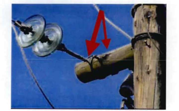
When insulators and wooden cross arms become dirty, small and steady leakage currents flow along the surface of the insulator and then into the wood itself. If this fire is not detected in time, it can cause the corresponding cross arm or the pole itself to break. A broken cross arm usually causes the outer phase conductor to hang between one and two meters above the ground.
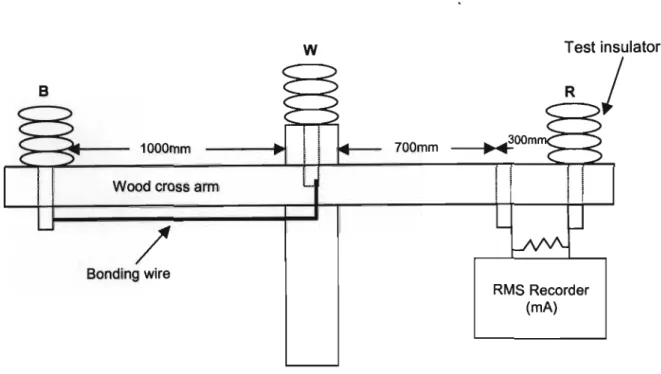
Safety is currently one of the highest priorities for Eskom Distribution, so there is a great need for pole top fire mitigation. This study is therefore aimed at inferring the effectiveness of implemented pole top fire mitigation techniques. 41 Figure 3 - 12: Laboratory test prepared for artificial pollution tests on wooden cross arms (Loxton, 1996). 42 Figure 3 - 13: Results of leakage currents at different lengths used and at different pollutions.
INTRODUCTION 1.1 Background
Motivation
The researcher focuses on the underlying mechanisms that cause burn-in, which underpin the performance of the Eskom distribution infrastructure and hinder the quality of business supply. In this study, the researcher provides statistics on the occurrence of Pole Top fires in KZN. The researcher also investigates the causes of the pole-top fires and provides an understanding of them.
A critical analysis of the effectiveness of technically feasible mitigation techniques over the past decade has been conducted. Therefore, this study aims to conclude whether the bonding mitigation technique that was implemented at Eskom Distribution actually reduces or even eliminates Pole Top fires or whether fires can still occur due to the combined phenomena of neutral displacement and electric field. The researcher also examines other technical alternatives to minimize Pole Top fires and proposes only those that are truly technically feasible.
Outline of chapters
For Eskom, incidents of the above nature create legal, financial, safety and publicity risks and should be minimized or even eliminated, while still providing affordable energy to the population. By analyzing a complex problem of this nature, possible and effective mitigation measures can be identified. The researcher also critically analyzes the different initial designs implemented since the early 1990s and then the different types of combustion experienced.
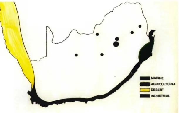
It focuses on the mechanisms of fire and its control parameters, field and laboratory investigations, bonding of line hardware and insulation coordination. Furthermore, the researcher explains why the phenomenon is common in KwaZulu - Natal although other areas use the same design of wooden pole structures. The last chapter concludes by highlighting the researcher's findings and whether the objectives of this study have been achieved.
POLE TOP FIRES IN KWAZULU -NATAL
The extent of Pole Top Fires in KZN
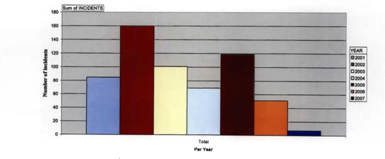
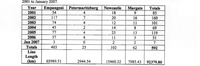
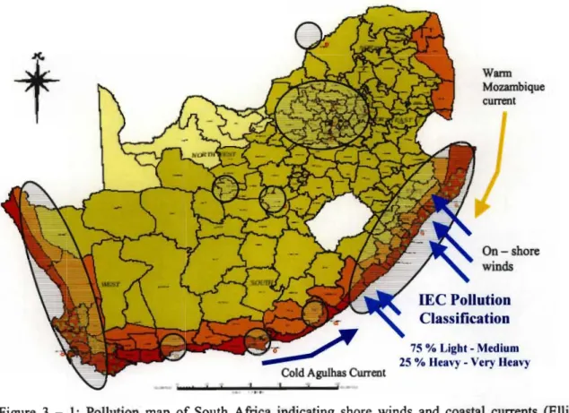
Accurate statistics of the phenomenon have been collected by the Eskom Distribution Plant Department and these are presented below for the FSA (Bouwer, 2006). The following tables and graphs show the number of pole top fire incidents and the total subsequent hours lost MYA. Note from the table that the number of incidents in Empangeni FSA is much higher than those in other areas.
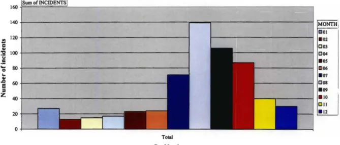
There are statistics available on pole fires on overhead 11 and 33kV lines for the same period and they are very similar. The data was also filtered and consolidated into the total number of incidents per month. The graph below illustrates the seasonal pattern of Pole Top Fires from January 1, 2001 through January 2007.
09 OOB .10
Various designs leading to different types of burning
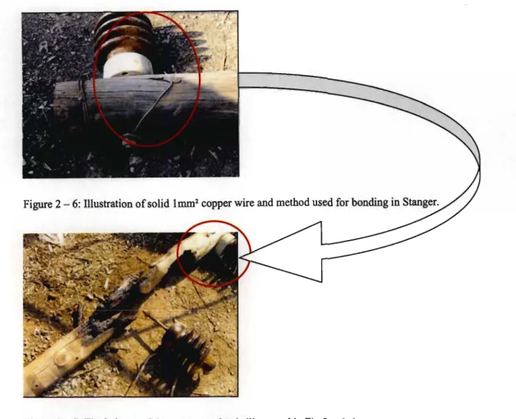
The bond provides an alternative means for leakage currents to flow away from the insulator and the wooden surface of the cross arm. As can be seen from Figure 2 - 5, the method did not work as the cross arm was badly burned. In this type of installation, the leakage current flowed in both the copper wire and the surface of the cross arm.
Thus, it is speculated that the burning started from the inner part of the cross wing. It was speculated that a higher stress gradient existed in the U-bolt brace than in the cross arm. There is sufficient evidence to suggest that the combustion started from the inside of the cross arm.
LITERATURE REVIEW
Severe tracking from an insulator base that was pressed against the surface of the crossarm. During the dusk and early morning hours, humidity and light wetting are common. The unbonded side of the wishbone was drilled 300mm from the outer insulator pin to accommodate a dummy pin to be fitted.
Many parts of the network near Mambrui experienced burning of wooden cross arms (Britten, 1995). Another goal was to deduce the applicability of the solutions used in the two organizations. Most of the fires occurred on the wooden cross arms and rarely on the main pole.
The replacement of the porcelain pin-type insulators of 33 kV (with a specific creep of 17 to 22 mm/kV) by porcelain line post insulators (with a specific creep of 25 mm/kV). A ground return leakage current on the order of 1 mA RMS means that the insulator leakage currents will typically exceed a few milliamps. Copper wire was secured in grooves filed 1000mm apart in the surface of the cross arm.
Further tests were carried out on the upper cross member to determine the effect of the retained dry strip in the center of the cross member. The silicon sheet was wrapped around the center of the cross arm and attached at both ends with a piece of copper wire. Distilled water was lightly sprayed over the entire surface of the cross arm and the insulator to wet the surfaces and thus trigger current activity.
Tests were also aimed at examining the area around the base of the isolator under clean and contaminated conditions. The base of the insulator developed sparks that were carried into the wood by the contamination dripping into the area. That is, leakage current amplitude of lmA (RMS) sustains the ignition of the wooden cross arm.
Artificial pollution tests on wood cross arms
CRITICAL ANALYSIS OF EFFECTIVE BONDING
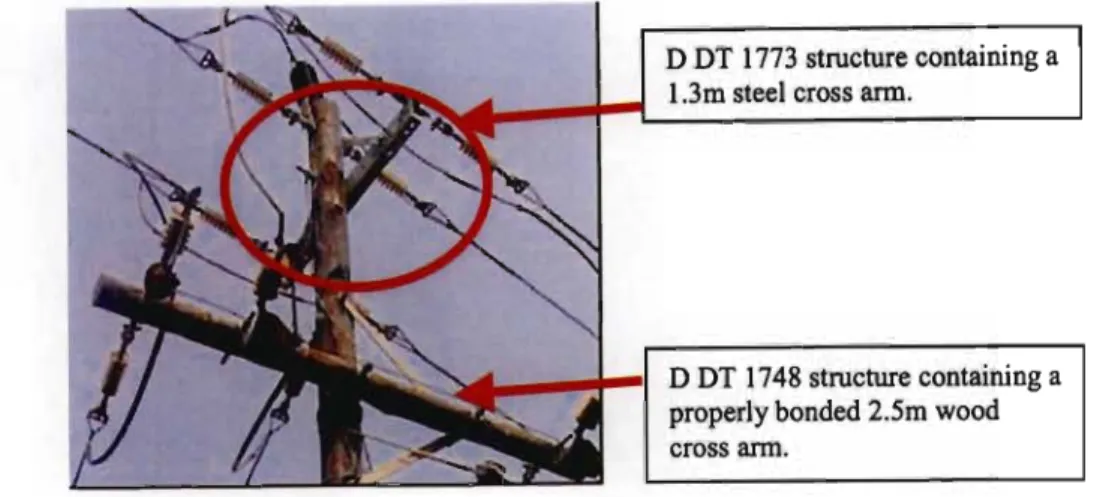
There were no visible signs of tracking or leakage current activity on the surface of the wooden cross arm. The post splintered at the through bolt between the wooden post and the steel cross arm. Likewise, the resistance of the wooden cross arm is very high (possibly also in the mega-ohm range).
The steel beam was separated from the wooden bar construction, and the wood was subsequently cross-sectionally determined. Long rod type silicone insulators with specific creepage of 31 mm/kV were used on the steel cross arm. The threaded rods that attached the steel cross arm and brace straps to the wooden bar were loose.
The underside of the steel cross was pressed tightly against the wooden post. There was little or no visible contamination on the post on the underside of the steel cross. There was no evidence of surface tracking/sparking from the underside of the steel cross to the wood surface.
The upper side of the steel cross had a small air gap of approximately 3 mm from the wooden post. There was also evidence of very light tracking/sparking from the corner edge of the upper side of the steel cross arm on the wood surface. Therefore, the distance from the base of the insulator to the surface of the wood is 5 mm.
Note that the cross arm spindle can be compared to the core of the cable.
CONCLUSIONS AND RECOMMENDATIONS
- l Conclusions
However, the researcher's research showed a poor implementation of the bonding principle before 2000. However, as highlighted in the literature review, it is recommended that the activity between the insulator spindle and the interior of the wooden cross arm be further investigated. along with the protection method. It is recommended that you apply fireproof paint to the inside of the threaded rod hole on the post and allow it to dry before installing the cross arm.
The same applies to the lower end of the bracing strap that supports the steel cross arm. This paint should be applied around the wooden bar and should cover the entire surface of the steel cross arm and the steel bracing strap that comes into contact with the wood. The idea is to retighten any loose threaded rods and maintain the effectiveness of the retarding paint.
If capless post insulators have been used, the leakage path between the edge of the insulator base and the spindle will be along the crossbar, leading to likely heating. To avoid this, a slotted disc (16mm) of galvanized steel (approximately 2mm x 110mm diameter) will need to be inserted between the insulator base and the crossbar to provide an alternative leakage path. The plate must be inserted so that the notch is perpendicular to the centerline of the cross.
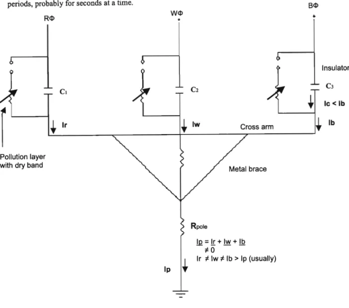
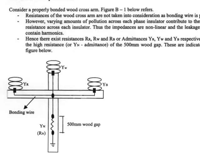
Intact structures: run the bonding wire up the pole, terminating 500mm below the three-phase circuit. The resistances of the wooden cross are not taken into account because the bonding wire is present. Note that the pole itself has a finite resistance to true ground and thus forms the power system ground.
This potential difference creates a high electric field that exists between the bonding wire and wooden surface or between the inside of the insulator spindle and the inside of the wooden cross arm. It is this high electric field that causes sparks between these surfaces and consequently burns to start from inside the cross arm.
EP 303 ASSEMBLED
Books 1
Measurement of Site Contamination Severity and Its Use in Insulator Sizing for AC Systems, Study Committee Working Group 04 Report No. 22kV Investigation of a wooden pole fire in KwaZulu - Natal: Effect of specific insulation creep on leakage current activity.