Chapter 5
Stormwater
TABLE OF CONTENTS
CHAPTER 5 STORMWATER
INTRODUCTION ... 1
5 PURPOSE ... 1
5.1 Performance Outcomes ... 1
5.2 Referenced Documents ... 2
5.2.1 Resource Management Plans ... 2
5.2.2 Building Code ... 2
5.2.3 External Standards ... 2
STANDARDS ... 4
5.3 Design Approach ... 4
Mandatory Matters ... 4
5.3.1 Stormwater effects ... 4
5.3.2 Water sensitive design ... 5
Good Practice ... 6
5.3.3 WSD device design ... 6
5.3.4 Catchment Planning ... 7
5.3.5 Safety in Design ... 7
5.3.6 Durability ... 8
5.3.7 Ownership and access ... 8
5.3.8 Easements for stormwater reticulation ... 8
5.4 System Design ... 9
Mandatory Requirements ... 9
5.4.1 System Components ... 9
5.4.2 Primary Stormwater System ... 9
5.4.3 Secondary Stormwater System ... 9
5.4.4 Debris flow ... 11
5.4.5 Freeboards... 11
5.4.6 Design Standards ... 12
5.4.7 Stormwater Quality ... 13
5.4.8 Stormwater Treatment Requirements (water quality) ... 13
5.4.9 Stream Bank Erosion Control and Stream Health ... 16
5.4.10 Infiltration requirements (base flows) ... 16
5.4.11 Extended detention requirements (stream bank erosion) ... 17
5.4.12 Stormwater Quantity Control ... 18
5.4.13 Detention requirements (Flooding) ... 18
5.4.14 Detention tanks ... 19
5.4.15 Detention basins, ponds and wetlands ... 19
Good Practice ... 20
5.4.16 Runoff calculations ... 20
5.4.17 Rainfall Data ... 21
5.4.18 Climate change ... 21
5.4.19 Seismic Design and Liquefaction ... 21
5.5 Design Solutions ... 22
Mandatory Matters ... 22
5.5.1 Open Channel Design ... 22
Good Practice ... 23
5.5.2 Piping of natural watercourses ... 23
5.5.3 Piped Reticulation ... 24
5.5.4 Pipe specifications ... 25
5.5.5 Pipe cover ... 26
5.5.6 Pipe connections ... 27
5.5.7 Manholes ... 27
5.5.8 Pumped stormwater systems ... 28
5.5.9 Non- pumped pressurised stormwater system ... 28
5.5.10 Inlets and outlets ... 29
5.5.11 Outfall water levels ... 29
5.5.12 Culverts ... 30
5.5.13 Culvert and Sump Blockage ... 30
5.5.14 Sumps ... 30
5.5.15 Discharge to soakage ... 32
5.5.16 Access to stormwater features ... 33
5.6 Construction and Installation ... 34
Mandatory Matters ... 34
5.6.1 General ... 34
5.6.2 Health and safety ... 34
5.6.3 Trenching ... 34
5.6.4 Bedding of pipes ... 36
5.6.5 Pipe installation ... 36
5.6.6 Manholes and access points ... 37
5.6.7 Concrete protection for pipes... 37
5.6.8 Groundwater and trench stops ... 38
5.6.9 Inspection and Testing ... 38
Mandatory Matters ... 38
5.6.10 General ... 39
5.6.11 Closed-Circuit Television (CCTV) Inspection ... 39
5.6.12 Pressure Testing ... 39
LIST OF TABLES
Table 5-1 Minimum Standards for Stormwater Design, Materials, Construction and Maintenance ... 2Table 5-2 Useful references for Stormwater Design, Materials, Construction and Maintenance ... 3
Table 5-3 Effects of Stormwater Discharges ... 5
Table 5-4 Minimum freeboard requirements ... 12
Table 5-5 Stormwater System Design Capacity Requirements Nelson ... 13
Table 5-6 First Flush Requirements ... 14
Table 5-7 Infiltration Requirements ... 17
Table 5-8 Extended Detention Requirements... 18
Table 5-9 Detention Requirements Summary ... 18
Table 5-10 Pipe Roughness ... 24
Table 5-11 Energy Loss ... 25
Table 5-12 Minimum Specification for Public Stormwater Pipes ... 25
Table 5-13 Pipe Cover Requirements ... 26
Table 5-14 Required Pipe Access Openings and Limiting Requirements ... 28
Table 5-15 Required Sump Locations and Limiting Requirements ... 31 Table 5-16 Water Stop Spacing ... 38
LIST OF FIGURES
Figure 5-1 Stormwater control points along the rainfall spectrum (adapted from Clayton & Schuler, 1996 and Auckland Council TR035/2013)... 4
CHAPTER 5 STORMWATER
INTRODUCTION
5 PURPOSE
The purpose of this section is to outline standards and good practice matters for the design and construction of stormwater systems for land development and subdivision in the Nelson and Tasman Districts. These aim to achieve flood management, environmental and amenity expectations in an effective and efficient matter. In all situations the provisions of the Nelson Tasman Land Development Manual (NTLDM) are also subject to the applicable Resource Management Plan (RMP).
The performance outcomes for the design and construction of stormwater systems sought by the standards and good practice matters in this document are as follows:
a) A management solution that is based on a holistic catchment-based assessment, including consideration of topography, soil and slope, vegetation, built development, existing drainage patterns, freshwater resources, stormwater network infrastructure, natural values and natural hazards;
b) An integrated design approach to stormwater management, which accommodates stormwater functions including access for maintenance and operations, as well as amenity, recreation and ecological values;
c) A network that manages stormwater flows to a standard that minimises people and property from harm or damage and nuisance effects, especially from risk to safety, health and well-being;
d) A management approach that aims to improve water quality;
e) Devices and design solutions that are robust, durable and easily maintained;
f) A whole-of-life operations, maintenance and replacement or renewal programme that is clearly described, costed, and can be afforded;
g) A stormwater system design that takes into account the foreseeable demands of future development;
h) A resilient network infrastructure that performs well against the risk of geotechnical, seismic, flood hazards and coastal hazards (erosion and inundation);
i) A design that maintains or improves values associated with freshwater resources, including riparian management and in-stream habitat values;
j) Stormwater assets that have high amenity value, and shared use of open-space areas where practicable and agreed to by Reserves and Facilities Manager;
k) A network that maintains a high visual amenity that enhances the value of adjoining property and neighbourhood values as a whole.
All performance outcomes are also subject to the applicable Resource Management Plan objectives and policies and appropriate bylaws, which take precedence over the requirements of the Nelson Tasman Land Development Manual (NTLDM).
The requirements set out in this chapter address matters that are specific to Council asset creation or activities that may have an impact on an asset. They are subject to the Nelson City and Tasman District Resource Management Plans as well as relevant National Environmental Standards and National Policy Statement: Freshwater Management.
Stormwater is also regulated within the Building Act and NZ Building Code (NZBC). As part of the building consent application process, stormwater run-off must be addressed by providing appropriate plans and specifications that demonstrate compliance with the performance requirements of NZBC clause E1,
“Surface Water”. The information required includes, but is not limited to, the size, fall (gradient) and setting out of the drainage, details of surface water sumps (eg. for drainage of a driveway surface), and provision of access points.
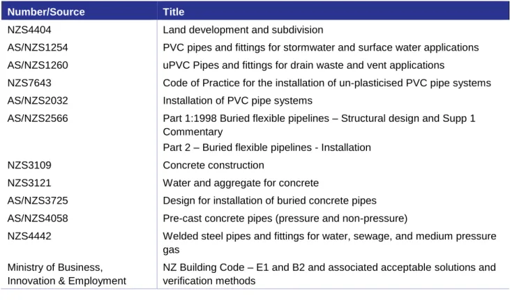
In addition to the standards of this document, the standards set out in Table 5-1 also apply unless specified otherwise. Where an Act or National Standards document is referenced, this shall be the current version including any associated amendments.
Table 5-1 Minimum Standards for Stormwater Design, Materials, Construction and Maintenance
Number/Source Title
NZS4404 Land development and subdivision
AS/NZS1254 PVC pipes and fittings for stormwater and surface water applications AS/NZS1260 uPVC Pipes and fittings for drain waste and vent applications
NZS7643 Code of Practice for the installation of un-plasticised PVC pipe systems
AS/NZS2032 Installation of PVC pipe systems
AS/NZS2566 Part 1:1998 Buried flexible pipelines – Structural design and Supp 1 Commentary
Part 2 – Buried flexible pipelines - Installation
NZS3109 Concrete construction
NZS3121 Water and aggregate for concrete
AS/NZS3725 Design for installation of buried concrete pipes AS/NZS4058 Pre-cast concrete pipes (pressure and non-pressure)
NZS4442 Welded steel pipes and fittings for water, sewage, and medium pressure gas
Ministry of Business, Innovation & Employment
NZ Building Code – E1 and B2 and associated acceptable solutions and verification methods
Table 5-2 sets out additional and related documents which may be useful references for designers.
Table 5-2 Useful references for Stormwater Design, Materials, Construction and Maintenance
Author / Organisation Title
Auckland Council Stormwater management devices in the Auckland
region. Auckland Council guideline document, GD2017/001 (GD01)
Auckland Council Water Sensitive Design for Stormwater, March
2015 Guideline Document 2015/004
Auckland Council Technical Report TR2013/018: Hydraulic Energy
Management - inlet and outlet design for treatment devices
Auckland Council Technical Report TR2013/040: Stormwater
Disposal via Soakage
NIWA New Zealand Fish Passage Guidelines, for
structures up to 4 metres, April 2018
Hamilton City Council Three Waters Management Practice Notes,
Hamilton City Council, HCC01- HCC07
Hamilton City Council Guidelines – Soak up your Stormwater
Ministry for Primary Industries (MPI) National Plant Pest Accord (NPPA) List
NZTA SP/M/022: 2013 - Bridge Manual
NZTA F2:2013 - Specification for Pipe Subsoil Drain
Construction
Water New Zealand NZ Pipe Inspection Manual 3rd Edition
New Zealand Society of Large Dams (NZSOLD) Dam safety Guidelines 2015
Christchurch City Council Waterways, Wetlands and Drainage Guide
Nelson City Council Nelson City Council/Department of Conservation
Living Heritage - Growing Native Plants in Nelson Tasman District Council Tasman District Council Native Plant Restoration
Lists
Nelson City Council/Tasman District Council Calculating minimum ground and floor levels for subdivision and new buildings, Tasman District Council and Nelson City Council, Inundation Practice Note 2019.
Nelson City Council/ Tasman District Council Wetland Practice Note for Nelson City and Tasman District Council 2019
Bioretention Practice Note for Nelson City and Tasman District Council 2019
Landcare Applying Low Impact Design and Water Sensitive
Design in Nelson Tasman, June 2016 Tasman District Council website Te Tau Ihu Mahi Tuna – Nelson/North
Marlborough Eel Management Plan
STANDARDS
This section outlines the main components of any stormwater network, and applied principles that underpin Council’s approach to stormwater management.
The following matters are requirements for the design of stormwater management:
Figure 5-1 Stormwater control points along the rainfall spectrum (adapted from Clayton &
Schuler, 1996 and Auckland Council TR035/2013).
Annual Exceedance Probability (AEP)
Rainfall depth
Zone 1: water quality control
Zone 2: stream channel erosion control
Zone 3: flood control
99% 1%
Note:
The distribution of rainfall events can be divided into three classes by recurrence interval. The first class has the most frequent rainfall events, which are targeted for water quality control and ground water recharge. Storms in zones two and three are water quantity storms, for which the control objectives are channel erosion and flood control (adapted from Clayton & Schuler, 1996).
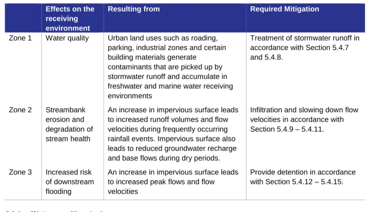
Table 5-3 Effects of Stormwater Discharges Effects on the
receiving environment
Resulting from Required Mitigation
Zone 1 Water quality Urban land uses such as roading, parking, industrial zones and certain building materials generate
contaminants that are picked up by stormwater runoff and accumulate in freshwater and marine water receiving environments
Treatment of stormwater runoff in accordance with Section 5.4.7 and 5.4.8.
Zone 2 Streambank erosion and degradation of stream health
An increase in impervious surface leads to increased runoff volumes and flow velocities during frequently occurring rainfall events. Impervious surface also leads to reduced groundwater recharge and base flows during dry periods.
Infiltration and slowing down flow velocities in accordance with Section 5.4.9 – 5.4.11.
Zone 3 Increased risk of downstream flooding
An increase in impervious surface leads to increased peak flows and flow velocities
Provide detention in accordance with Section 5.4.12 – 5.4.15.
a) Protect and enhance the values and functions of natural ecosystems;
b) Address stormwater effects as close to source as possible;
c) Mimic natural systems and processes for stormwater management;
d) Support inter-disciplinary planning and design where practicable and;
e) WSD principles shall be considered during the initial design and planning.
Note:
Effective implementation of WSD principles requires more planning and design input than traditional piped stormwater systems. Good planning and design early in the development process maximises the cost effectiveness of WSD. Further guidance on the implementation of WSD is available in the Auckland Council guideline document GD2015/004 (Water Sensitive Design for Stormwater).
a) Step 1: Project scoping;
i. Identify stakeholders
ii. Early consultation with Council iii. Define objectives and outcomes.
b) Step 2: Understanding the site’s constraints and opportunities;
i. Geology, slopes, groundwater, hydrology, zoning, vegetation, cultural values, etc ii. Minimise site disturbance, earthworks and compaction
iii. Limit impervious surface
iv. Preserve and utilise existing hydrology.
c) Step 3: Define stormwater mitigation requirements;
i. Identify detention, treatment and stream protection requirements ii. Identify stormwater management solutions and location
iii. Identify potential combined functions.
d) Step 4: Device design;
i. Determine device sizing and footprint of potential stormwater solutions ii. Undertake life cycle costing
iii. Iterations and refinements
iv. Design preferred stormwater management solution.
a) Wetlands;
b) Vegetated and grassed swales;
c) Bioretention (i.e. raingardens, tree pits, infiltration basins);
d) Rainwater tanks;
e) Permeable paving;
f) Green roofs.
a) Stormwater management devices in the Auckland region. Auckland Council guideline document, GD2017/001 (GD01);
b) Hamilton City Council Three Waters Practice Notes: HCC01 to HCC07;
c) Nelson City Council/ Tasman District Council, Bioretention and wetland Practice Notes, version 1, June 2017.
a) Surface permeability affecting on-site infiltration should be maximised to reduce runoff and optimise groundwater recharge and impervious surfaces should be minimised;
b) Existing drainage patterns and topographic features, including subsoil features of drainage, should be retained where possible, and restored if degraded through previous development. Stormwater management methods should mimic natural drainage processes where practicable;
c) Earthworks should be minimised to reduce the potential for erosion, soil compaction and loss of topsoil;
d) A treatment train approach to stormwater quality should be considered to target specific contaminants of concern. A treatment train may include combinations of on-site mitigation, minimising site disturbance, re-vegetation, instream and riparian habitat restoration, and communal off-site stormwater treatment;
e) Council may require further details about any device or method used in the proposed stormwater design, including whole-of-life cost implications.
a) Private drain – drain serving one property;
b) Common private drain – drain serving two to five properties;
c) Public drain – drain serving six properties or more and/or covered by easement in gross or is within road reserve.
a) Maintenance purposes;
b) Preserving the route for relaying the reticulation in the future;
c) Avoiding likely positions for buildings, garages, carports and retaining walls; and d) Located on the northern side of dwellings.
a) Within ROWs or driveways;
b) Outside probable building envelopes;
c) Clear of obstructions;
d) Adjacent to boundaries – but no closer than 0.6m to outside edge of the pipe or structure;
e) Parallel to boundaries.
This section outlines stormwater system design requirements relating to the key components of the total system and the capacity of them.
The following matters are mandatory requirements for the design of the stormwater system.
a) Natural systems such as streams (ephemeral, intermittent and permanent) and overland flow paths; and
b) Built systems such as constructed channels and drains, piped networks, manholes, inlets/
outlets, stormwater quality treatment devices (i.e. wetlands, swales, raingardens etc), detention dams, diversion devices, and pump stations.
a) Aligned with natural flow paths wherever possible;
b) Via roads, public walkways or right of ways wherever possible;
c) Kept clear of proposed building sites;
d) Protected by legal easements in favour of Council;
e) Subject to an encumbrance placed on the title of the land which prohibits ground reshaping and the erection of any barriers to the secondary flows;
f) Appropriately formed and/or hardened to make their presence obvious and durable;
g) Designed for public safety.
a) Legal easements in favour of Council and;
b) Consent notice on the title (top of bank to top of bank) to protect the drain or flowpath from development.
Pedestrian safety dflow x vave < 0.3 m2/s
Vehicle safety The height of the total energy line (water level + energy head) shall not exceed 300 mm above roadway surface at the low point of the cross section.
Flow along the road should not exceed dflow x vave < 0.3 m2/s, except with specific floodway design and additional protection.
Where:
dflow = flow depth in the channel adjacent to the kerb, eg, measured from the invert of the channel (m).
vave = average flow velocity of the flow (m/s).
Note:
A maximum depth is required for vehicle safety because small cars can float in depths exceeding 300mm.
Any sites that do not comply with the above thresholds require approval from the Engineering Manager and shall be clearly identified on engineering plans.
F = 3000/D, where:
F = freeboard in metres (limits 0.5m-5m)
D = distance to source (base of hill, entrance to gully) in metres.
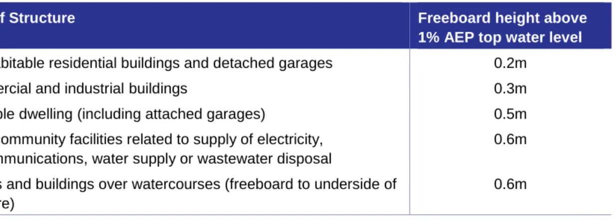
Table 5-4 Minimum freeboard requirements
Type of Structure Freeboard height above
1% AEP top water level Non-habitable residential buildings and detached garages 0.2m
Commercial and industrial buildings 0.3m
Habitable dwelling (including attached garages) 0.5m
Major community facilities related to supply of electricity, telecommunications, water supply or wastewater disposal
0.6m Bridges and buildings over watercourses (freeboard to underside of
structure)
0.6m
Note:
i) Structures need to comply with freeboard requirements of the NZ building code and those may be separate from and in addition to freeboard requirements in Table 5-5.
ii) Specific freeboard requirements apply to areas that are at risk of coastal inundation and shall be in accordance with Inundation Practice Note: Calculating minimum ground and floor levels for subdivision and new buildings, Tasman District Council and Nelson City Council, April 2018.
iii) Any proposed deviation from the freeboard requirements in Table 5-5 shall be approved by the Engineering Manager.
a) 500mm where surface water has a depth of 100mm or more and extends from the building directly to a road or carpark, other than a carpark for a single dwelling.
b) 150mm for all other cases Note:
The 500mm freeboard allows for waves generated by vehicles. Such waves will not be sustained unless there is at least 100mm depth of water and an unobstructed path from the point where the wave is generated to the building.
Table 5-5 Stormwater System Design Capacity Requirements Nelson
Nelson City Council Tasman District Council Primary systems: stormwater -
pipes culverts and open channels
Flood Management - streams and rivers
6.67% AEP + climate change (15-year ARI)
1%AEP + climate change (100-year ARI)
10% AEP + climate change (10-year ARI)
1% AEP + climate change (100-year ARI)
Secondary systems 1% AEP + climate change (100-year ARI)
1% AEP + climate change (100-year ARI)
Dam spillway failure and
freeboard sensitivity analysis Probable Maximum Precipitation (PMP).
Note:
Redevelopment of roads and parking areas is defined as works that involve the reconstruction and redesign of the road carriageway or parking area to allow for an increased capacity. It does not include isolated maintenance or restoration works such as resurfacing.
a) All State Highways, Arterial and Principal roads;
b) Collector roads with an actual or forecast average annual daily traffic (AADT) of greater than 5,000 at full development;
c) Parking areas, exposed to rainfall, greater than 1,000m2 total surface area or more than 50 (AADT), including access ways;
d) All roads and paved areas (including metaled surfaces) within new industrial and commercial developments;
e) Service stations;
f) Unpainted or treated building materials such as copper or zinc roofing.
a) Local access roads and cul-de-sacs within residential developments with AADT less than 5000 at full development;
b) Parking areas smaller than 1,000m2 or less than 50 AADT;
c) Footpaths and cycle paths;
d) Metaled roads;
e) Patios;
f) Sport fields;
g) Any pervious surface, including pervious pavement.
Table 5-6 First Flush Requirements
Device type First flush treatment requirement
Volume based treatment device 25mm of rainfall depth from the total area of high contaminant generating surface
Flow based treatment devices 10mm/hour of runoff from the total area of high contaminant generating surface.
a) Stormwater management devices in the Auckland region. Auckland Council Guideline Document, GD2017/001 (GD01);
b) Hamilton City Council, Three Waters Management practice notes HCC01 – HCC07;
c) Nelson City Council/Tasman District Council, Bioretention and Wetland Practice Notes, 2019.
Good Practice
Designing for treatment of contaminants in addition to the key contaminants of concern (5.4.7.2), including temperature increases, nutrients, gross pollutants and some household contaminants.
Designing for treatment of runoff from surfaces in addition to high contaminant
generating surfaces (5.5.8.2) such as lower hierarchy roads (< 5,000 AADT) and small carparks (<1,000m2), driveways and patios.
Implementation of catchment devices such as wetlands.
Education and increased awareness through signage.
i)
Note:
Design considerations for soft engineering are site-specific and their implementation should be carefully considered on a case-by-case basis.
a) Infiltration of stormwater into the ground and;
b) Extended detention.
Infiltration is an integral part of natural drainage processes and shall be integrated into the design of the stormwater system. Infiltration reduces stormwater runoff and contributes to groundwater recharge and base flows in streams. Infiltration of stormwater for greenfield, infill and brownfield developments shall be provided in accordance with Table 5-7 below.
Table 5-7 Infiltration Requirements
Situation Infiltration requirements
Development, greenfield, infill or brownfield, that creates no additional impervious area or where impervious surface is reduced.
None required.
Development, greenfield, infill or brownfield, located outside groundwater recharge zones*.
None required.
Development, greenfield, infill or brownfield, creating additional impervious surface greater than 50m2 and is located within groundwater recharge zones*.
A minimum of 5 mm of runoff from the newly created impervious surfaces* shall be infiltrated within 24 hours to offset the loss of the initial abstraction of 5 mm of rainfall that uncompacted pre-development pervious areas have.
*If at the time of consent application, the total newly created impervious surface is unknown, the developer should take into account an estimated total new impervious surface, based on the anticipated future use of the site and maximum allowable coverage percentage under the relevant zoning rules.
Note:
* Recharge zones are defined as:
i) Areas that are identified as having low risk for slope stability issues;
ii) Areas with a permeability rate of at least 5mm/hr (as determined through permeability test method described in in E1/VM1 Section 9.0); and
iii) Areas with a seasonal high ground water table no less than one meter below the surface.
Extended detention is required to detain and slow down flows from frequently occurring storm events.
Extended detention of stormwater for greenfield, infill and brownfield developments shall be provided in accordance with Table 5-8 below.
Table 5-8 Extended Detention Requirements
Situation Extended detention requirements
Development, greenfield, infill or brownfield, which does not create a direct discharge into a stream or open drain.
None required.
Development, greenfield, infill or brownfield, creating additional impervious surface greater than 50m2 and a new and direct discharge point into a stream or open drain (lined or unlined).
Implement extended detention according to the following:
i) Provide storage of the extended detention volume (EDV) that is the equivalent of a 50% AEP event with a two-hour duration, slowly release over 24-hours.
ii) Any volume that is infiltrated on site may be subtracted from the extended
detention volume.
Table 5-9 Detention Requirements Summary
Situation Detention requirements
Development, greenfield, infill or brownfield that generates no additional impervious area.
None required.
Development, greenfield, infill or brownfield, where the downstream network has sufficient capacity for the increased flows (based on maximum probable development of the catchment) and/or where there are no existing flood risks that would be increased as a result of the development.
None required.
(Network capacity to be confirmed by Council).
Greenfield development that results in additional impervious surface, where the downstream receiving network has
insufficient capacity for the increased flow (based on maximum probable development of the catchment) and/or where there are known flood risks downstream.
Provide detention so that post development peak flows shall not exceed pre-development peak flows for the 10% AEP (10-year ARI) and 1%
AEP (100-year ARI).
Brownfield and infill development that results in additional impervious surface, greater than 50m2 where the downstream receiving network has insufficient capacity for the increased flow (based on maximum probable development of the catchment) and/or where there are known flood risks downstream.
50 litres/m2 of additional impervious area.
Minimum 20mm orifice for detention up to 5000 litres. Otherwise drain in no less than 24 hours
a) Stormwater management devices in the Auckland region. Auckland Council Guideline Document, GD2017/001 section C5.0.
b) Hamilton City Council, Three Waters Management practice note, HCC06.
a) Side slope stability and safety considerations;
b) Ease of access and maintenance, including mowing and silt cleanout;
c) Shape and contour for amenity value;
d) The effectiveness of the inlet and outlet structure;
e) Secondary overflow options;
f) Dam or bank failure;
g) Silt traps;
h) Fish passage, habitats and birdlife enhancements;
i) Road frontage of not less than 30m width;
j) Pedestrian links to other reserves;
k) Safety fencing;
l) Vegetation islands, shading.
a) Stormwater management devices in the Auckland region. Auckland Council Guideline Document, GD2017/001 section C5.0.
b) Hamilton City Council, Three Waters Management practice note, HCC05.
a) Q = runoff.
b) C = runoff coefficient.
c) I = rainfall intensity.
d) A = area of catchment.
The following standards relate to the design of specific solutions used in the management of stormwater.
These standards are requirements for the design of specific stormwater management solutions.
e) Secondary flow corridors to carry the 1% AEP flows;
f) Recreational spaces for the community;
g) Habitat for aquatic flora and fauna to promote biodiversity;
h) Open channels shall be designed with appropriate riparian vegetation cover and incorporate natural features such as meanders, ponds and riffles, native plants, shading, fish passage and refuge, invertebrate and bird habitat;
i) The design shall include maintenance access without compromise of the riparian and in- stream ecological values. Additional land will be required to avoid this compromise;
j) The design of open channels based on Manning’s Formula calculations is acceptable unless unusual circumstances exist. Full details of the associated assumptions and calculations shall be presented to Council.
Mannings formula is Q = (AR2/3 S1/2) / n*
where:
Q = flow m³/s
R = hydraulic radius (m) S = slope of surface A = water section area, m².
*n = roughness coefficient
a) Overhanging vegetation: planting of riparian margins should be aimed at achieving 70% shading of a wetted width of three metres or less after 20 years of tree growth.
b) Meander patterns: the radii and wavelength of stream bends need to be appropriate to the location and simulate natural streams in a similar setting.
c) Bank shape: allow for variety in steeper bank shapes and flatter beach bars as deposition zones for sediment.
d) Water depth: allow for variety of water depths with deep pools and shallower sections such as rapids and riffles.
e) Substrate: Sufficient gravel thickness, cobble and woody debris are essential components for healthy streams.
f) Flood plain: Flat benches that are designed to flood in high flows may also provide for other functions such as spawning sites and capturing sediment that would otherwise clog the channel.
a) Resource consent will be required.
b) Pipes shall be used or subsoil drains (Type B) shall be laid at the invert level of the pipe and connected to manholes, to ensure groundwater levels are not forced to rise. Where pipe routes differ from the original stream course, sufficient protection from seepage in the original stream bed shall be provided.
c) Secondary overland flow paths shall be provided as per Section 5.4.
a) Excavation on existing services.
b) The future renewal of the assets.
c) The provision of additional future services.
Table 5-10 Pipe Roughness
Method Pipe Roughness
Mannings formula n = 0.013
Colebrook-White formula ks = 1.5mm up to 450mm pipe
ks = 0.6 for over 450mm pipes
Table 5-11 Energy Loss
Energy loss he = k v²/2g (h in metres, v in m/s)
Type K
Sharp pipe entry (from reservoir) 0.5
90° manhole (depending on radius) 0.5 to 1.0
Velocity head loss at outlet 1.0
Where:
k = coefficient of entrainment (dimensionless)
= 0.004 for smooth pipes
= 0.008 for cast-in-situ concrete culverts V = velocity (m/s)
R = hydraulic radius (m)
g = acceleration due to gravity (9.81 m/s)
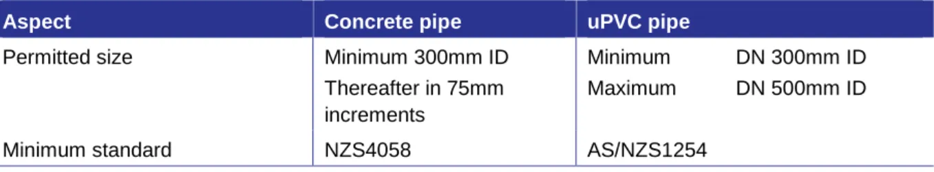
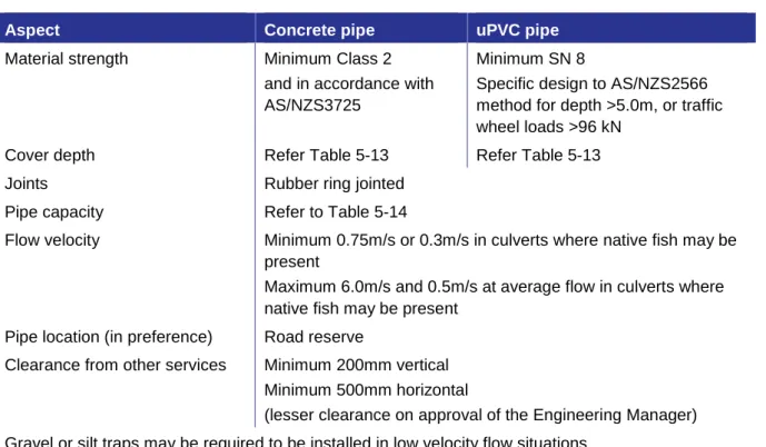
Table 5-12 sets out the minimum specifications for public stormwater pipe design.
Table 5-12 Minimum Specification for Public Stormwater Pipes
Aspect Concrete pipe uPVC pipe
Permitted size Minimum 300mm ID
Thereafter in 75mm increments
Minimum DN 300mm ID
Maximum DN 500mm ID
Minimum standard NZS4058 AS/NZS1254
Aspect Concrete pipe uPVC pipe
Material strength Minimum Class 2
and in accordance with AS/NZS3725
Minimum SN 8
Specific design to AS/NZS2566 method for depth >5.0m, or traffic wheel loads >96 kN
Cover depth Refer Table 5-13 Refer Table 5-13
Joints Rubber ring jointed
Pipe capacity Refer to Table 5-14
Flow velocity Minimum 0.75m/s or 0.3m/s in culverts where native fish may be present
Maximum 6.0m/s and 0.5m/s at average flow in culverts where native fish may be present
Pipe location (in preference) Road reserve
Clearance from other services Minimum 200mm vertical Minimum 500mm horizontal
(lesser clearance on approval of the Engineering Manager) Gravel or silt traps may be required to be installed in low velocity flow situations.
Table 5-13 Pipe Cover Requirements
Location of Pipe Minimum Cover Required
Concrete Pipe PVC Pipe Areas subject to highway traffic loading eg., within road carriageway 600mm 750mm Areas subject to light traffic loading outside road eg. ROWs,
driveways, car parks and berms
450mm 600mm
Areas never subject to traffic loading 300mm 450mm
a) The appropriate class of concrete pipe is specified, and cover is according to the manufacturer's specification. Details of pipe class design shall be determined by use of the pipe class software (http://www.cpaa.asn.au/General/design-software-pipeclass.html) and provided with engineering plans;
b) Or concrete pipes are concrete encased; or c) PVC pipes are concrete capped.
a) In all subdivisions, a stormwater system of a minimum 100mm diameter shall be provided to at least 1.0m inside the boundary of each lot (or body of each lot if served by ROW). Note:
The pipe end shall be painted green to denote that it is a stormwater pipe and each connection shall be marked by a 75mm x 25mm marker stake suitably identified.
b) On generally flat land, sloping at 1-in-50 or less, each connection shall be capable of serving the entire building area of the section by gravity.
c) On land steeper than 1-in-50 every effort shall be made to serve the entire section. Where this proves to be impossible and the servicing of the site is limited the area on each lot capable of being serviced shall be shown on the Engineering Drawing.
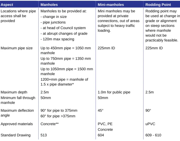
Table 5-14 Required Pipe Access Openings and Limiting Requirements
Aspect Manholes Mini-manholes Rodding Point
Locations where pipe access shall be provided
Manholes to be provided at:
- change in size - pipe junctions
- at head of Council system - at abrupt changes of grade - 120m max spacing
Mini manholes may be provided at private connections, out of areas subject to heavy traffic loading.
Rodding point may be used at change in grade or alignment on steep sections where manhole would not be practicably feasible.
Maximum pipe size Up to 450mm pipe = 1050 mm manhole
Up to 750mm pipe = 1350 mm manhole
Up to 1050mm pipe = 1500 mm manhole
1200+mm pipe = manhole of 1.5 x pipe diameter*
225mm ID 225mm ID
Maximum depth 2.5m 1.0m for public pipe 2.5m
Minimum fall through manhole
50mm 50mm
Maximum deflection angle
90° for pipe to 375mm 60° for pipe >375mm
45° 90°
Approved materials Concrete** PVC, PE
Concrete
uPVC
Standard Drawing 513 604 609 - 610
*Factory-made “T” manholes will be permitted for pipes of 1350mm diameter and over, subject to the approval of Council.
Design shall be generally consistent with Concrete Pipe Association of Australasia (CPAA) Guidance Note
a) The likelihood of blockage given the availability of debris (including sand for tidal outlets);
b) The likelihood of debris transport given the flow path slope and catchment land use;
c) The size of openings that may block; and
d) The consequences of that blockage including floor level flooding, unsafe flows, excessive erosion, structural damage or damage to historical areas.
e) The risk assessment may require allowance for 100% blockage of pipes greater than 1500mm in some circumstances.
Table 5-15 Required Sump Locations and Limiting Requirements Location Standard Back
Entry Sumps
Standard Back Entry Sumps with flow diverter
Double Back Entry Sump
Approved locations At each tangent point of the channel on the upstream side of road intersections where the grade is flatter than 1-in-10 (10%, 5.74 degrees).
At any low spot in a channel.
Serving any right-of- way.
At each tangent point of the channel on the upstream side of road intersections where the grade is equal to or steeper than 1-in-10.
Where the channel upslope of the sump is steeper than 1 in 10.
Where area of the catchment warrants the provision of adequate stormwater entry.
Where the length of kerb and channel draining to a low point is excessive.
At a low point at the head of a cul-de-sac or street where secondary flow paths flow through private property.
Minimum lateral pipe size
225mm ID 225mm ID 300mm ID
Standard Drawing 516 - 519
Maximum depth 1300mm
Maximum distance between sumps*
Standard kerb: 100m Mountable kerb: 60m
(Subject to specific design on a case-by-case basis) Approved materials Concrete
a) Lateral alignment of the sump top shall be within a maximum of plus or minus 10mm of the design line of the kerb and channel.
b) The skew of the sump top in relation to the kerb and channel alignment shall be within 10mm of being parallel.
c) The sump shall be placed within 20mm of being vertical and 20mm of the millimetres of the maximum depth.
d) The finished level of the sump shall ensure compliance with the tolerance requirements for kerb and channel finished level as per the Transportation section of this manual.
e) The vertical alignment of kerb and channel shall be designed to ensure that no low point requiring a standard sump will coincide with any kerb and channel curve of less than 50m radius (except at the turning heads of cul-de-sacs).
a) Detailed site-specific geotechnical investigation, including comprehensive soakage testing (in accordance with Auckland Council Technical Report TR2013/040: Stormwater Disposal via Soakage) across the proposed soakage areas.
b) An assessment of the predominant soakage paths and soakage rates, both vertical and horizontal that make up the soakage zone and confirm the extent of ‘horizontal’ soakage and the effects that this may cause on land stability, both of the current and future lot(s) and on any other adjacent property and or existing or future structures that are built or likely to be built within the soakage zone.
c) Specific documentation of the likely winter peak groundwater table level.
d) Detailed calculations, drawings and field soakage test results
e) Device design details for on-site stormwater disposal of primary and secondary flows f) System blockage shall be considered in the design of the system and a secondary flowpath
shall be kept unobstructed at all times.
g) Stormwater treatment shall be provided in accordance with 5.4.8.
a) An all-weather access track for trucks and wheeled excavators.
b) Three (3) metres wide for travel able to be accessed by an 8.2t axle weight rigid vehicle for its entire length.
c) 4m minimum width where excavators will swivel to access the feature and providing sufficient space for operation of plant to work on the feature.
The following requirements are mandatory in respect of the installation of stormwater management systems.
a) In a sand environment – sand.
b) For PVC and flexible pipes – NZTA M4 AP20 or as per AS/NZS2566, Appendix G.
c) For concrete pipes – NZTA M4 AP20 or as per AS/NZS3725, Table 6.
d) Specific design can be submitted for appraisal by Council on a case by case basis.
a) In areas subject to vehicle traffic where the cover of the pipe barrel is, or will be, less than that required for the class of pipe as specified by the pipe manufacturer.
b) In areas other than those covered above, where the cover over the barrel of the pipe is or will be less than 300mm, irrespective of the type or class of pipe.
Where water stops are required, they should be provided at the intervals shown in Table 5-16.
Table 5-16 Water Stop Spacing
Pipe Grade Maximum Spacing
1 in 15, 6.5% grade 3.8 degrees or steeper 12m
1 in 25, 4% grade, 2.5 degrees 15m
1 in 50, 2% grade, 1.15 degrees 30m
1 in 100, 1% grade, 0.57 degrees 60m
Note – Intermediate grades (and spacing) are determined by interpolation.
a) Environmentally sensitive areas;
b) Built-up or congested areas to minimise disruption and reinstatement;
c) Major road crossings;
d) Significant vegetation;
e) Vehicle crossings and areas with high quality paving surface;
f) Where there is a large number of existing services;
g) Pipes used for trenchless installation shall have suitable mechanically restrained joints, specifically designed for trenchless application, which may include integral restraint, seal systems, or heat fusion welded joints.
Mandatory requirements for piped network inspections and testing are as follows.
a) The pipe is horizontally misaligned or deformed by more than 5% of the pipe diameter.
b) The pipe has visible dips or ponding of water.
c) The pipe has visible defects, such as open or displaced joints, defective or protruding laterals, cracked barrels or similar defects.
TASMAN DISTRICT COUNCIL NELSON CITY COUNCIL
GROUP MANAGER INFRASTRUCTURE, NELSON
DATE
SECONDARY FLOW PATH IN PRIVATE
PROPERTY - GROUND / FENCE TREATMENT
TASMAN DISTRICT COUNCIL
GROUP MANAGER INFRASTRUCTURE, NELSON
DATE NELSON - TASMAN
RECHARGE AND SEASONAL SOAKAGE
502
TASMAN DISTRICT COUNCIL
GROUP MANAGER INFRASTRUCTURE, NELSON
DATE
WATERWAY CONCEPTS
°
°
TASMAN DISTRICT COUNCIL NELSON CITY COUNCIL
GROUP MANAGER INFRASTRUCTURE, NELSON
DATE NELSON - TASMAN
150 - 400mmØ OUTFALL DETAILS &
DRAINAGE WATERWAY CONCEPTS
504
TASMAN DISTRICT COUNCIL
GROUP MANAGER INFRASTRUCTURE, NELSON
DATE
TO STREAMS - DETAILS
TASMAN DISTRICT COUNCIL
GROUP MANAGER INFRASTRUCTURE, NELSON
DATE NELSON - TASMAN
INTAKE STRUCTURE
506
TASMAN DISTRICT COUNCIL
GROUP MANAGER INFRASTRUCTURE, NELSON
DATE
SCHEDULE
TASMAN DISTRICT COUNCIL
GROUP MANAGER INFRASTRUCTURE, NELSON
DATE NELSON - TASMAN
WITH DEBRIS TRAPS (TYPES A & C)
508
TASMAN DISTRICT COUNCIL
GROUP MANAGER INFRASTRUCTURE, NELSON
DATE
WITH DEBRIS TRAPS (TYPE B)
TASMAN DISTRICT COUNCIL
GROUP MANAGER INFRASTRUCTURE, NELSON
DATE NELSON - TASMAN
SECONDARY INTAKE DEBRIS GRILL
510
TASMAN DISTRICT COUNCIL
GROUP MANAGER INFRASTRUCTURE, NELSON
DATE
MANHOLE (1 OF 2)
TASMAN DISTRICT COUNCIL
GROUP MANAGER INFRASTRUCTURE, NELSON
DATE NELSON - TASMAN
MANHOLE - SECTIONS (2 OF 2)
512
* *
* *
TASMAN DISTRICT COUNCIL NELSON CITY COUNCIL
GROUP MANAGER INFRASTRUCTURE, NELSON
DATE
FLOW DIVERTER
(1 OF 2)
TASMAN DISTRICT COUNCIL
GROUP MANAGER INFRASTRUCTURE, NELSON
DATE NELSON - TASMAN
FLOW DIVERTER (2 OF 2)
514
TASMAN DISTRICT COUNCIL
GROUP MANAGER INFRASTRUCTURE, NELSON
DATE
& CHANNEL - PLAN & ELEVATION (1 OF 2)
TASMAN DISTRICT COUNCIL
GROUP MANAGER INFRASTRUCTURE, NELSON
DATE NELSON - TASMAN
& CHANNEL - SECTION (2 OF 2)
516
TASMAN DISTRICT COUNCIL
GROUP MANAGER INFRASTRUCTURE, NELSON
DATE
MOUNTABLE KERB & CHANNEL
TASMAN DISTRICT COUNCIL
GROUP MANAGER INFRASTRUCTURE, NELSON
DATE NELSON - TASMAN
GRATE (1 OF 2)
518
TASMAN DISTRICT COUNCIL
GROUP MANAGER INFRASTRUCTURE, NELSON
DATE
MECHANISM DETAIL (2 OF 2)
TASMAN DISTRICT COUNCIL
GROUP MANAGER INFRASTRUCTURE, NELSON
DATE NELSON - TASMAN
BERM SUMP (1 OF 2)
520
TASMAN DISTRICT COUNCIL
GROUP MANAGER INFRASTRUCTURE, NELSON
DATE
(2 OF 2)
TASMAN DISTRICT COUNCIL
GROUP MANAGER INFRASTRUCTURE, NELSON
DATE NELSON - TASMAN
YARD SUMP
522
TASMAN DISTRICT COUNCIL
GROUP MANAGER INFRASTRUCTURE, NELSON
DATE
TASMAN DISTRICT COUNCIL
GROUP MANAGER INFRASTRUCTURE, NELSON
DATE NELSON - TASMAN
MODIFICATION OF STANDARD SUMP GRATE
524
TASMAN DISTRICT COUNCIL NELSON CITY COUNCIL
GROUP MANAGER INFRASTRUCTURE, NELSON
DATE
INFILL BUBBLE - UP SUMP (SEALED
HOUSE DOWNPIPE CONNECTION ONLY)
TASMAN DISTRICT COUNCIL
GROUP MANAGER INFRASTRUCTURE, NELSON
DATE NELSON - TASMAN
STORMWATER PIPES
526
TASMAN DISTRICT COUNCIL
GROUP MANAGER INFRASTRUCTURE, NELSON