This is to certify that this project entitled "AC Motor Speed Control And RPM Count" is being done by the following students under my direct supervision. This project work was carried out by them in the laboratories of the Department of Electrical and Electronic Engineering under the Faculty of Engineering, Sonargaon University (SU) in partial fulfillment of the requirements for the degree of Bachelor of Science in Electrical and Electronic Engineering. The report titled as on “AC Motor Speed Control And RPM Count” was prepared to meet the requirement of our practicum program.
First of all, we would like to express our gratitude to the authority of the University for allowing us to do our internship. In particular, we would like to thank our respected teacher Jannatul Nazrana, Lecturer, Department of Electrical and Electronic Engineering, SU. Finally, we would like to thank again the honorable Vice-Chancellor of SU, Professor Dr.
This device is an integrated system; is built using a microcontroller, an alpha-numeric LCD module and an infrared system to detect the rotation of the fan whose speed is being measured. In automobiles, it is used as a gauge that indicates the speed (RPM) of the engine shaft driving the transmission, usually in thousands of revolutions per minute. Essential for measuring shaft or engine rotational speed in any vehicle.
This device enables the driver of the motor vehicle to track the rotating speed and thereby to adjust the accelerator and the gear to the driving conditions.
Project Outline
Summary
Benefits Of Using Microcontrollers
Different Types Of Microcontrollers
There are two types of microcontrollers - Harvard memory architecture microcontrollers and Princeton memory architecture microcontrollers.
Features Of Microcontrollers
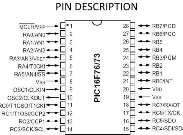
Microcontroller PIC16F73 Pin Diagram
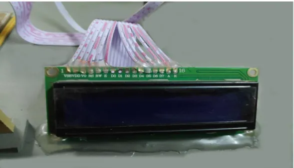
LCD Display
- LCD Display Pin Descriptions
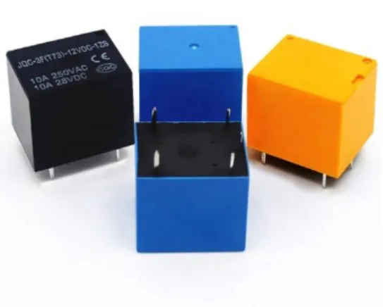
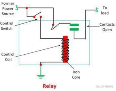
Relay
- Working Principle of Relay
- Uses of Relays
The small power relay has only one contact and the high power relay has two contacts for opening the switch. Power is supplied to the coil through the contacts of the load and control switch. Due to this magnetic field, the upper arm of the magnet attracts the lower arm.
If the contact is already closed, it moves in the opposite direction, thus opening the contacts. Relays are used to control high voltage circuits using low voltage signals. Similarly, they are used to control high-current circuits using low-current signals.
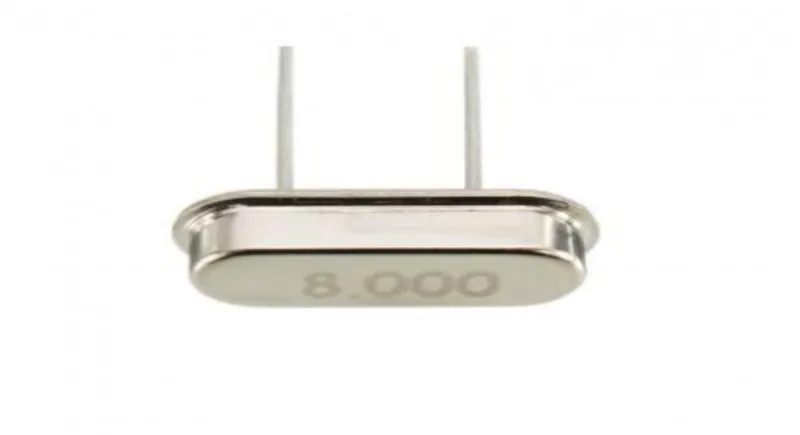
Crystal Oscillator
Step Down Transformer
Capacitor
Resistor
Diode
A P-N junction is the simplest form of diode which behaves as an ideal short circuit when forward biased and an ideal open circuit when reverse biased. Apart from simple PN junction diodes, there are different types of diodes, although the basic principles are more or less the same. So a special arrangement of diodes can convert AC to pulsating DC, and hence, is sometimes called a rectifier.
Voltage Regulator (7085)
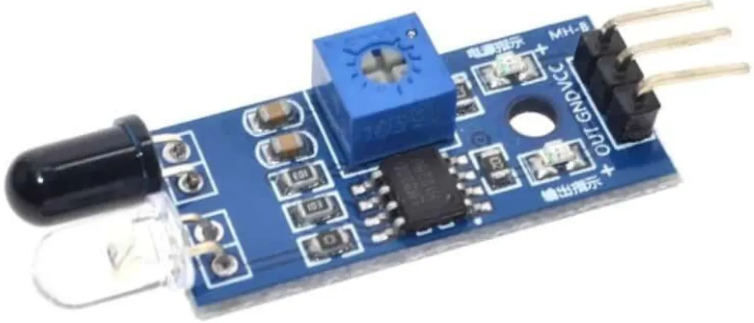
IR Sensor
- Uses Of IR Sensors
IR sensors are now widely used in motion detectors, which are used in building installations to switch on lights or in alarm systems to detect unwanted guests.
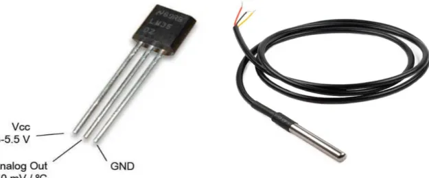
Temperature Sensor
DIAC
- DIAC Construction
- DIAC Working Principle
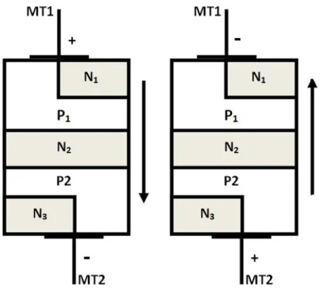
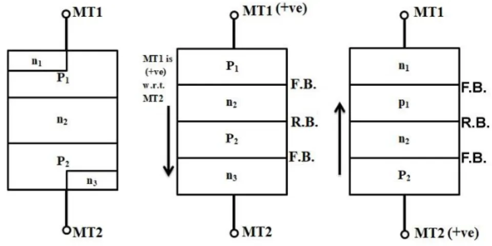
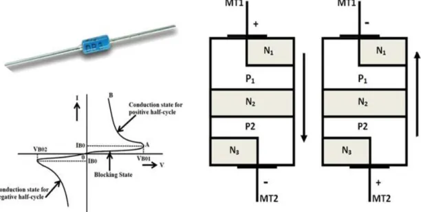
The construction of the DIAC will be quite similar to the structure of the transistor, but they have some differences such as the DIAC has no base terminal, all three layers have the same amount of doping, and it gives symmetrical switching properties in both polarities. of the applied voltage. As mentioned earlier, the DIAC has two terminals namely MT1 and MT2 and can supply current in both directions. DIAC is made of a five-layer structure; the layers closest to the terminals are the combination of positive and negative layers.
When the voltage is transferred to the terminals, the layer with respective polarity is activated after the voltage, this combination of both the polarities helps to operate the DIAC in both the directions. The picture above shows the clear operation of the DIAC with the polarities respectively. Consider the MT1 terminal as positive, then the P1 layer near MT1 will be activated, so the conduction will occur in the order of P1-N2-P2-N3.
When current flows from MT1 to MT2, the junction between P1-N2 and P2-N3 is forward biased and the junction between N2-P2 is reverse biased. Similarly, if we consider MT2 terminal as positive, the P2 layer near MT2 will be activated and the conduction will occur in the order of P2-N2-P1-N1. The current will flow from MT2 to MT1 and the junctions between P2-N2 and P1-N1 are forward biased and the junction Between N2-P1 is reverse biased.
TRIAC
- TRIAC Construction
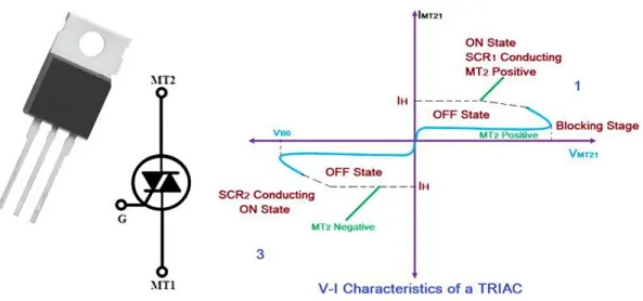
The gate terminal is designed in a way to have ohmic contact with both the N and P regions, which helps the device to be activated with both positive and negative polarities. The TRIAC can go into conduction if the applied voltage is equal to the breakdown voltage, but the preferred way to turn on a TRIAC is by providing a gate pulse, either positive or negative. If the gate current is high, a very small amount of voltage is sufficient to turn on the TRIAC.
Since the TRIAC is bidirectional and has the ability to turn on with either polarity of the gate pulse, it can operate in four different types of modes of operation as listed below. MT2 is positive relative to MT1 with positive gate polarity relative to MT1. MT2 is positive relative to MT1 with negative gate polarity relative to MT1.
MT2 is negative with respect to MT1 with a gate polarity negative with respect to MT1. MT2 is negative with respect to MT1 with a positive gate polarity with respect to MT1.
System Design And Development Page No
- Working Function Of Our Project
- Block Diagram Of Hardware Implementation
- Circuit Diagram Of Whole System
- Summary
- Introduction
- Cost Analysis
- Project Overview
- Before Start The System
- After Start The System
- AC Motor Speed Control Diagram
- Discussion
- Summary
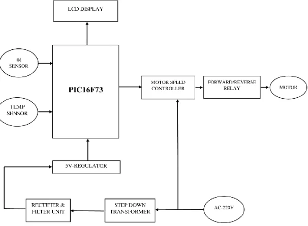
First, we supply 220 V AC in a step-down transformer. Then the transformer steps down the voltage to 12 V AC. At the output pin of this regulator, we get a constant 5V DC which is used for various devices in this project (such as microcontroller, LCD display, IR sensor, etc.). It provides an analog signal to the microcontroller and then the microcontroller converts it into a digital signal and sends it to the LCD screen.
We connect a crystal oscillator to pin number 9 and 10 that generate the clock pulse with the active microcontroller. The motor will make forward rotation when the relay switch is OFF and the motor will make reverse rotation when the switch is ON. Conduction rotation condition, the positive terminal of 220V AC is connected to the running terminal of the motor and the capacitor connected between the common terminal and the running one.
The condition of reverse rotation, 220V AC positive terminal connected to motor Starting terminal and capacitor connected between common and starting terminal. The button controls the gate current of the TRIAC through a circuit consisting of a DIAC and a capacitor. The output is given in rpm (revolutions per minute) and the number of digits increases from 3 to 5.
In Figure 4.3.2, we can see that the motor is running and the motor speed controller circuit is measuring this and sending it to the microcontroller. The microcontroller displays this on the LCD screen. Designing, constructing and designing analyzes of the circuit is the basic goal of our project. First we did a project, then we used this concept in this project by studying books, searching the internet and discussing it with my teacher.
First we discuss about System Control, use then we show the configuration of the project and after we show the project when it is working.
CONCLUSIONS Page No
- Limitations Of The Work
- Future Scopes
- Microcontroller
- Block Diagram Of Microcontroller
- Pin Configuration of Microcontroller
- Relay Structure
- Transformer
- Capacitor Construction
- Resistor Working Principle
- Voltage Regulator Working Block Diagram
- LM 7805
- DIAC Working with Application Circuits
- TRIAC Symbol & V-I Characteristics Curve
- TRIAC Symbol
- Connection Diagram of AC Motor RPM Count
- Before Start The system
- After Start The system
- Project Cost Analysis
If we use any other board like Adriano Mega, we can add many other functions. There are many possibilities for development in this project, for example we can use a LASER instead of a motor control circuit.