Smart Attendance System
BY
Md. Farukul Islam ID 151-15-5022
This Report Presented in Partial Fulfillment of the Requirements for the Degree of Bachelor of Science in Computer Science and Engineering
Supervised By
Moushumi Zaman Bonny Senior Lecturer Department of CSE
Daffodil International University
DAFFODIL INTERNATIONAL UNIVERSITY
DHAKA, BANGLADESH DECEMBER 10, 2018
APPROVAL
This Project titled “SMART ATTENDANCE SYSTEM”, submitted by Md. Farukul Islam (151-15-5022) to the Department of Computer Science and Engineering, Daffodil International University, has been accepted as satisfactory for the partial fulfillment of the requirements for the degree of B.Sc. in Computer Science and Engineering (BSc) and approved as to its style and contents. The presentation has been held on December 10, 2018.
BOARD OF EXAMINERS
Dr. Syed Akhter Hossain Chairman
Professor and Head
Department of Computer Science and Engineering Faculty of Science & Information Technology Daffodil International University
Narayan Ranjan Chakraborty Internal Examiner
Assistant Professor
Department of Computer Science and Engineering Faculty of Science & Information Technology Daffodil International University
Md. Tarek Habib Internal Examiner
Assistant Professor
Department of Computer Science and Engineering Faculty of Science & Information Technology Daffodil International University
Jahangirnagar University
DECLARATION
We hereby to declare that, this project has been done by us under the supervision of Moushumi Zaman Bonny, Senior Lecturer, Department of CSE, Daffodil International University. We also declare that neither this project nor any part of this project has been submitted elsewhere for award of any degree or diploma.
Supervised by
Moushumi Zaman Bonny Senior Lecturer
Department of Computer Science and Engineering Daffodil International University
Co-Supervised by
Saiful Islam Lecturer
Department of Computer Science and Engineering Daffodil International University
Submitted by
Md. Farukul Islam ID: 151-15-5022
Department of Computer Science and Engineering Daffodil International University
ACKNOWLEDGEMENT
First, we express our heartiest thanks and gratefulness to almighty God for His divine blessing makes us possible to complete the final year project/internship successfully.
We really grateful and wish our profound our indebtedness to Moushumi Zaman Bonny, Senior Lecturer, Department of CSE Daffodil International University, Dhaka.
Deep Knowledge & keen interest of our supervisor in the field of “Development Project”
to carry out this project. Her endless patience, scholarly guidance, continual encouragement, constant and energetic supervision, constructive criticism, valuable advice, reading many inferior drafts and correcting them at all stage have made it possible to complete this project.
We would like to express our heartiest gratitude to Dr. Syed Akhter Hossain, Professor and Head, Department of CSE, for his kind help to finish our project and also to other faculty member and the staff of CSE department of Daffodil International University.
We would like to thank our entire course mate at Daffodil International University, who took part in this discussion while completing the course work.
Finally, we must acknowledge with due respect the constant support and patience of our parents.
ABSTRACT
This project is designed focusing on changing the behavior of our traditional attendance system. The main goal of this project is to handle the daily registration and calculating the attendance more easily and efficiently. The combination of an Android application and IOT device can make it happen. The target is to register the attendance via the application very easily. The device will hold the information of section and department of a person. A single scan can get the result. Further processing like saving the result, printing the result, uploading the result to a portal or database can be done by the application. Administration of a company or institution can handle and select who can use the application. Those who will use the application could select and scan a particular section or department based on his requirement. Uploading the result to the portal will calculate the ratio of attendance and absence of a person. For educational institutions, the portal will even calculate the mark based on their attendance. Implementation of this project can be a huge breakthrough. This attendance system is able to cope up with this digital era.
TABLE OF CONTENTS
CONTENTS PAGE NO
Board of Examiners i
Declaration ii
Acknowledgements iii
Abstract iv
CHAPTER
CHAPTER 1: INTRODUCTION
01-031.1. Introduction 01
1.2. Motivation 01
1.3. Objectives 02
1.4. Expected Outcome 02
1.5. Report Layout 03
CHAPTER 2: BACKGROUND
04-062.1. Introduction 04
2.2. Related Works 04
2.3. Comparative Studies 05
2.4. Scope of the Problem 05
2.5. Challenges 06
CHAPTER 3: REQUIREMENT SPECIFICATION
07-163.1. Business Process Modeling 07
3.2. Requirement Collection and Analysis 08
3.3. Use Case Modeling and Description 08
3.4. Activity Diagram 09
3.5. Logical Data Model 10-13
3.6. DFD (Data Flow Diagram) 14-15
3.7. Design Requirements 16
CHAPTER 4: DESIGN SPECIFICATION
17-224.1. Front-End Design 17
4.2. Back-End Design 07
4.3. Interaction Design and UX 19
4.4. Implementation Requirements 22
CHAPTER 5: IMPLEMENTATION AND TESTING
23-295.1. Implementation of database 23
5.2. Implementation of Front-End Design 23
5.3. Implementation of Interaction 25
5.4. Testing Implementation 26-29
CHAPTER 6: CONCLUSION AND FUTURE SCOPE
30-316.1. Discussion and Conclusion 30
6.2. Limitation 30
6.3. Scope of Further Development 31
REFERENCES
32-33APPENDICES
34-41Appendix A: Project Reflection 34
Appendix B: Related Diagrams 40
LIST OF FIGURES
FIGURES PAGE NO
Figure 3.1: Flow Chart of the system 07
Figure 3.2: Use Case Model of the system 09
Figure 3.3: Activity Diagram 10
Figure 3.4: Entity Relationship Diagram of the system 13
Figure 3.5: DFD Level-0 of the system 14
Figure 3.6: DFD Level-1 of the system 15
Figure 4.1: Dependencies and Libraries of Android 18
Figure 4.2: List of Android permissions 18
Figure 4.3: Web and Android login table structure 18
Figure 4.4: Web and Attendance table structure 19
Figure 4.5: Android login screen 19
Figure 4.6: Initial scan results with the filter code screen 20
Figure 4.7: Final Result after filtering screen 20
Figure 4.8: Web login screen 21
Figure 4.9: Web attendance portal 21
Figure 4.10: Web attendance portal with an attendance table 22
Figure 5.1: Android login screen code 23
Figure 5.2: Android login design 24
Figure 5.3: Web portal code 24
Figure 5.4: Web portal design 25
Figure5.5: Screenshot of attendance server 26
Figure A.1: Screenshot of application files of Android 33
Figure A.2: Screenshot of application files of Web 36
Figure B.1: Screenshot of directory file of Android 39
Figure B.2: Screenshot of directory file of Web 39
Figure B.3: Screenshot of XAMPP server 40
LIST OF TABLES
TABLES PAGE NO
Table 3.1: Entities and their Attributes 11
Table 3.2: Attributes of Login 11
Table 3.3: Attributes of Initial Scan Result 12
Table 3.4: Attributes of Attributes of Class Code 12
Table 3.5: Attributes of Final Result 12
Table 3.6: Attributes of Attendance Details 12
Table 4.1: List of the screen of Android platform 17
Table 4.2: List of the screen of the Web platform 17
CHAPTER 1 Introduction
1.1. Introduction
Time and technology is the most valuable part of life. Everyone may hear of a quote
“Time is Money”. We are in an era where we can only be successful by utilizing time.
And time utilization is only possible by using the latest technology. According to statistic organization Statista, a statistic named “Global digital population as of October 2018”
reveals that there are more than 4.1 billion of the world population uses internet [1]. And still, in our country, most of the organizations take attendance by paperwork or by inserting into computer one by one. This takes time and sometimes may seem boring by someone who takes and registers attendance every day. In educational organizations, if the class time is short and students are large in number, taking attendance can take more or less 20% of the class time. To reduce the cost of time and to make the system easier, I have developed this project named “Smart Attendance System”. The idea is to develop an android application and IOT based device which can take attendance by just scanning for once, collect information, register them into the required database and last of all count the number of objects automatically.
1.2. Motivation
Most of the schools and colleges of our country use register books to take attendance. In my university, the existing system is online based but still manual. Teachers have to call the names or IDs and mark them in a sheet and upload it to the database. Or in a fingerprint based attendance system, everyone has scan their fingers one by one to register their attendance. Nowadays different universities and organizations are focusing on making everything online based. Here, Attendance system is a challenging part for all the organizations. So, to make the attendance system more effective and user-friendly,
Life is being easier day by day with the help of technologies. Then why not make our attendance system automated where it will be much easier.
1.3. Objectives
The objectives of the proposed system are as follows
Admin has all the type of authority.
To deal with an automated system in an easy way and efficient mannered.
Finding out a better solution than the existing one.
Analyzing the problems of the present systems.
Designing and implementing a complete, reliable and effective automated attendance system.
Designing the database.
Determine the customized software to be used.
Prepare the whole project (Coding phase).
Testing properly before releasing the project.
Recheck and repair (when necessary) any part of the proposed system before going for the final entrance.
1.4. Expected Outcome
This device is trustworthy. Electronic Devices are Error Free. They work based on how they are instructed. As it works with Android and the program it is carrying, no error is possible if there is any power issue in the chip or in the application.
It can work very fast. The application can scan and count very fast. As it needs only to turn on Wi-Fi and then scan with the application.
Both the application and chip is easy to use. The person to take attendance can do it by just opening the application, scan the available networks by clicking the scan button, insert the code for department, batch and class or section, filter the desired students and
click the register button to save the result. Users only have to switch on the device to give their attendance. And of course, charge the device when needed.
A web page is also available to see the results from the database and how many marks a student get for a certain amount of class given by the total marks for attendance.
1.5. Report Layout
The discussion about the introductory part of the project is in Chapter 1. Where Chapter 2 holds the discussion about the background. Background work includes the related work of this project and what this system offers comparing with the existing systems. In Chapter 3, the information about requirement specification is described. How the system works on a logical level is described in detail with related diagrams. Chapter 4 contains the details about design specification. How the project is implemented including the design of front end and back end configuration. Chapter 5 is about implementation and testing. Various types of testing that are done to find out the problems and errors in this system. In Chapter 6, information about the conclusion and future scope of this project is described.
CHAPTER 2 Background
2.1.Introduction
When we face problems, we invent a new way to solve the problem. This trend makes us civilized. And in this era, everything we do is being well furnished and digitalized. There is no such field where technology has not reached and developed anything yet. It is easy to work in a field of developing a project. On the other hand, it is also challenging. While the biometric system is still being developed, implementing such a system can be considered a step ahead. By fixing my goal, I have taken every preparation. This chapter reveals all my background studies to implement my project including the related works like this project and the challenges I faced during the implementation.
2.2.Related Works
Before I started working with this project, I searched for smart attendance systems that are available right now. And I came to know about some projects that are actually smart.
But the main problem of all those projects is they all take more time to register students, which is the main motivation of my project.
Some of the projects are
“IOT based smart attendance system” where an RF-ID (Arduino based) reader reads the particular ids of student and every student has to scan their id to get registered.
“QR based attendance system” where a device scans the QR codes of students by a camera and registers the students one by one. There is also barcode reader based project available that also works like this.
There is no such project still available that can register attendance at a time for a certain number of students.
2.3.Comparative Studies
According to my study in this field, this project is different from the existing systems. If this project is a success, it can open a new scope for various institutions. And I have the confidence that this project can play an important role in our institution. As Android devices are available this project is also easy to use the system. Some of the features may be similar to the existing systems. But the main focus of this project is very unique.
This system offers
Every student has a Wi-Fi enabled chip with a unique id.
All the authority is handled by the admin.
Attendance is stored in an online database.
There is no access of student to the portal.
Filtering a particular section.
Counting the number of attendance.
Storing them into the database section.
Admin can modify the database via an online admin portal.
Admin has to log in to the system to modify the database.
Mark of attendance is calculated by the online portal.
Fine of absence can also be calculated.
2.4. Scope of the Problem
The limitations of existing systems are a scope of this project. This system can reduce time than others. All at once is better than one by one for sure. This system can register all at once rather than one by one like others. In traditional registration, there is a huge waste of time. There are 5 to 10 minutes of time can be saved by this system in every class hour. Teachers or authorities do not have to calculate attendance mark and fine of absence anymore.
2.5.Challenges
There lie difficulties with great work. This system is a step ahead in comparison of other smart attendance systems. So the challenges are also more. As I have to work with android platform along with web and IOT device, it took so much effort to implement this project. The major challenges are
Building the Wi-Fi scanner to scan the devices.
Filtering particular students from the available Wi-Fi.
Passing the results to a different platform.
Storing the data to the database by giving the attendance to the present student in just a single submission and giving absence to others.
Making an application for only admins where there is no access to students.
Making the web portal for admins to modify and get the fines and marks of students.
To make sure the best outcome for this system and to overcome others.
And finally, making the whole system as user-friendly and as reliable as possible.
CHAPTER 3
Requirement Specification
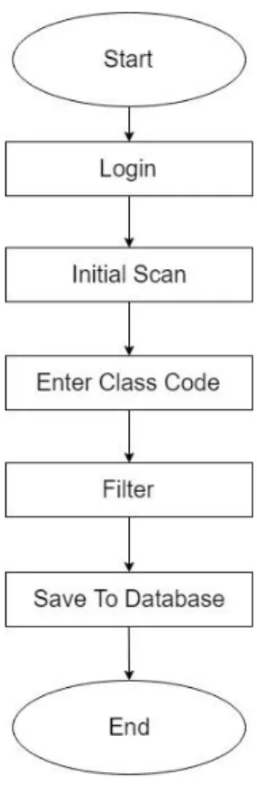
3.1.Business Process Modeling
Business process modeling is important to represent a system [2]. To analyze, improve and automate the system, process model like flow chart, activity diagram helps a lot.
Flowchart of the system is given below.
3.1.1. Flow Chart of the Proposed System
Visual diagrams or graphs can be more effective to describe a model than with words.
Here flow chart is given to explain the process clearly [3].
This flow chart shows the overall process of this system.
3.2.Requirement Collection and Analysis
Requirement collection and analysis or requirement engineering determines the user expectations for a new model or developed product. The features are called requirements.
Requirements have to be countable, relevant and detailed. These requirements are also called functional specifications.
3.2.1. Requirement Collection
To collect the requirements needed to survey some customer and organization to know their requirements. The online survey helped to understand the best features of similar projects and implement those to make it more efficient.
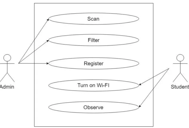
3.3.Use Case Modeling and Description
Use case modeling is needed to organize the requirements of this system [4]. The interaction of actor and the system for the different environment can be shown by use case model. Different goals of a system can be described in the same diagram. To know more about use case modeling, below description may help.
The boundary indicates the relation of the system with its surroundings. How the actors and individuals are related to the system according to their requirements and roles. It specifies the roles that are played the system with its users.
The use of use case model is this system is-
It organizes functional requirements and relations.
The goal of the system is defined easily.
The interactions of users are also described by this.
The path of starting and destination can be recorded.
The main flow of the system is described by the use case model.
The use case model of this system is given below.
Figure 3.2: Use Case Model of the system
3.4. Activity Diagram
Another important diagram to understand the basics and dynamic aspects of the system is an activity diagram [5]. The flow of work of a system is shown by the activity diagram. It is also one kind of flow chart that indicates the flow of work from one step to another.
The workflows from a mother node to its child node. The child node then becomes the mother node of its next step. The workflows may be sequential or can be branched. This type of diagram deals with the flow by joining them with arrows.
Though the main goal of the activity diagram is similar to the other four diagrams, it can explain the behavior of a system. Where the other four diagram shows the flow from one activity to another with messages. Thus the operation of the system can be described by an activity diagram.
Activity diagram can indicate the execution of the system using a step up and step down techniques of engineering.
Figure 3.3: Activity Diagram
3.5. Logical Data Model
As the analysis of business rules and to discover the attributes and relationship between different elements, now it is needed to develop an ERD (Entity Relationship Diagram) model. ERD describes the system in detail and performs logical representation between the data of this system.
3.5.1. Entities
The entities we get after performing analysis on system data which are represented in a rectangular shape in the diagram
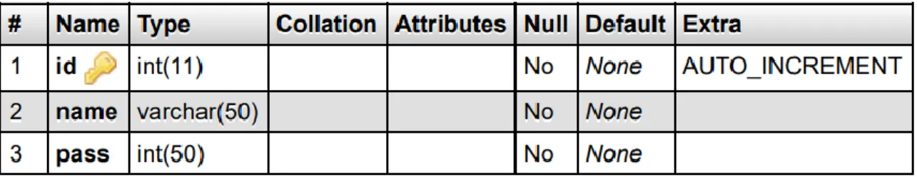
Login: Valid ID and password of admin.
InitialScanResult: Result that is found by searching initially.
ClassCode: The code that contains the department, batch, and section.
FinalResult: The result after filtering with the code.
AttendanceDetails: Details of Attendance.
3.5.2. Attributes
Attributes are properties of an entity. The entities we get by analyzing the system.
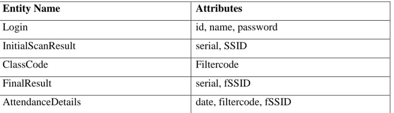
Table 3.1: Entities and their Attributes
Entity Name Attributes
Login id, name, password
InitialScanResult serial, SSID
ClassCode Filtercode
FinalResult serial, fSSID
AttendanceDetails date, filtercode, fSSID
Description of attributes of different entities is given below.
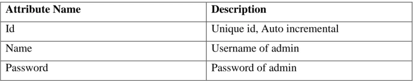
Table 3.2: Attributes of Login
Attribute Name Description
Id Unique id, Auto incremental
Name Username of admin
Password Password of admin
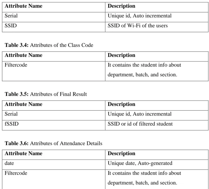
Table 3.3: Attributes of Initial Scan Result
Attribute Name Description
Serial Unique id, Auto incremental
SSID SSID of Wi-Fi of the users
Table 3.4: Attributes of the Class Code
Attribute Name Description
Filtercode It contains the student info about
department, batch, and section.
Table 3.5: Attributes of Final Result
Attribute Name Description
Serial Unique id, Auto incremental
fSSID SSID or id of filtered student
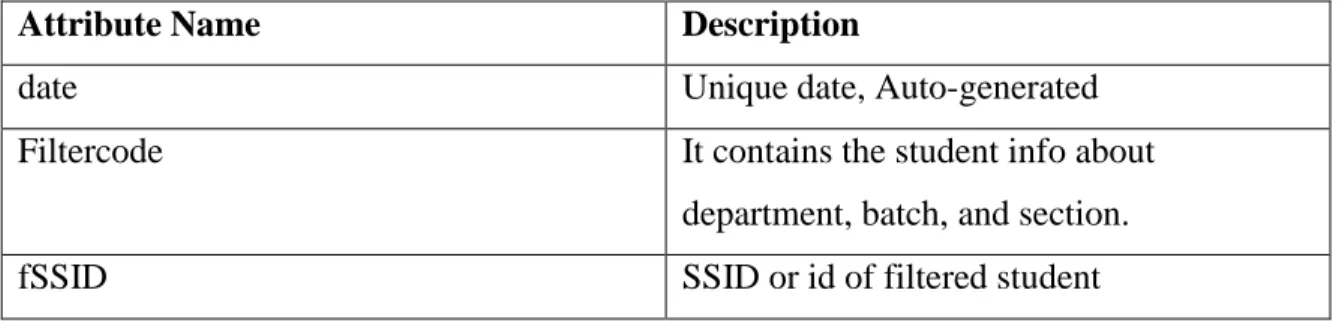
Table 3.6: Attributes of Attendance Details
Attribute Name Description
date Unique date, Auto-generated
Filtercode It contains the student info about
department, batch, and section.
fSSID SSID or id of filtered student
3.5.3. Entity Relationship Diagram
Entity relationship diagram is one kind of summary of all data structure of system [6].
For this system, the entity relationship diagram represents the database and some of the app field that is important for this system. The relationship between tables is also shown in this diagram. To know the flexibility and to observe the visual diagram, simplicity is a major concern. ERD helps to make it simple also. The interaction or communication of the entities is observable here.
The rectangular boxes represent entities of the system.
Four types of relationship belong to the entities.
Relationships are represented by –
o That represents a very strong relationship between entities.
There are three types of attributes that appear in this diagram.
Key attributes are represented by –
o It uniquely indicates a particular entity.
Attributes themselves are represented by –
Multilevel attributes are represented by – o It can contain multiple values.
ERD can be called as the blueprint of the database of a system.
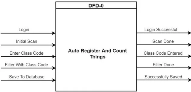
3.6. DFD (Data Flow Diagram)
To map the flow of information in a system, the Data Flow Diagram is needed [7]. DFD uses defined symbols like rectangles, circles, and arrows along with text labels. These symbols show the flow of information like data inputs, outputs, storage and flow between every destination.
DFD is very simple but helpful to understand the depth and level by digging into deeper to describe how the data are being handled.
There are two DFD levels that are used for this system: Level-0 and Level-1[8].
3.6.1. DFD Level-0
The top-level data flow diagram is a context diagram (Level-0). Level-0 DFD only contains one process node that indicates the function of the entire system and its relationship with other entities.
Level-0 DFD for this system is given below.
Figure 3.5: DFD Level-0 of the system
3.6.3. DFD Level-1
Level-1 DFD is used to know the sub functionality also along with the Level-0 information about the system. Each of the functions deals with one or more flow of data.
It generalizes the basic process of a system by providing deeper system knowledge.
Level-1 DFD can represent all the functionality of a system as a whole. The interaction of the system with the database is also shown by this level of DFD diagram.
Figure 3.6: DFD Level-1 of the system All of the above figures are drawn by using draw.io [9]
3.7.Design Requirements
Android
HTML
CSS
PHP
Java Script
MySqlCHAPTER 4 Design Specification
4.1. Front-End Design
Front end design includes the visual part of a project or a system. Here in this system, the following screens are available.
In this project, there are two platforms. One is Android and the other is Web.
Table 4.1: List of the screen of Android platform 1 Login
2 Initial scan list with filter code entry field 3 Filtered list screen with register button
Table 4.2: List of the screen of the Web platform 1 Login
2 Attendance table of whichever section admin wants
4.2. Back-End Design
This system offers some cool features to make taking attendance so easy. But it was difficult to implement this system as this contains two platforms to work with.
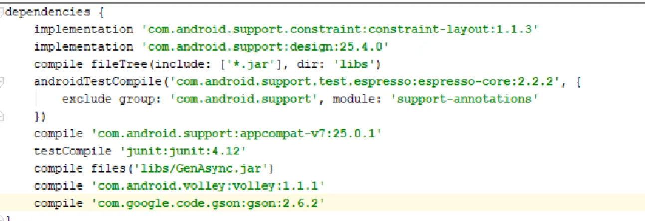
In the Android platform, there are many libraries that are included to implement the Wi- Fi scanner. Many variables are used to store data. Some of them are global and volatile as they are meant to store data to print values to a certain field. And some of them are used to pass values to the web platform. As this system has to print and pass more than one string, there are array lists and array adapters also.
To pass the values to from one activity to another activity I have used putExtra and getExtra methods.
To pass the values from Android platform to Web I have used JSON parsing with the help of GSON library [10].
All the dependencies with included libraries are given in the figure below [11].
Figure 4.1: Dependencies and Libraries of Android
Permissions that are needed to implement the system are given in the figure below [12].
Figure 4.2: List of Android permissions
And the back end of Web platforms includes below database table formation.
Figure 4.3: Web and Android login table structure
Figure 4.4: Web Attendance table structure 4.3. Interaction Design and UX
Interaction design is the user interface of a system. The screen view of a system by which a user can interact with. As for all system, the user experience is a matter of concern. No system is complete and good without a good user feedback.
The admin of this system is the only one who can use and operate this program. Both the Android application and web application is designed for the admin of this system.
Android user interface figures are given below.
Figure 4.6: Initial scan results with the filter code
Figure 4.7: Final Result after filtering
Figure 4.8: Web login screen
Figure 4.9: Web attendance portal
Figure 4.10: Web attendance portal with an attendance table
4.4. Implementation Requirements
Requirements for implementing Front End
This system is implemented with Android and Web programming. For Android, I have used Android Studio [13]. And for Web part, I have used Sublime Text [14].
Requirements for implementing Back End
To implement the database I have used XAMPP to connect the database with PHP and database is MySql database [15] [16].
Summary of languages and tools
Android Studio
Sublime Text
XAMPP
PHP
MySql
CHAPTER 5
Implementation and Testing
5.1.Implementation of database
To store all data and to use them back in both Android and Web application, every system needs a database. To implement the database, I have used XAMPP server and MySql language. Apache server of MySql server is also needed to run the Web application by localhost server.
The same database is required to run both Android and Web application.
5.2.Implementation of Front-End Design
Designing the front end of these two applications requires Android XML for Android and HTML and CSS and Bootstrap for the web [17]. An Android emulator and a web browser are needed to run the programs that are used to see the front end for Admin.
Sample File for Android design is given.
The above figure is the written code. The user interface of this code is given below.
Figure 5.2: Android login design Sample File for Web design is given below.
Figure 5.3: Web portal code
The above figure is the written code. The user interface of this code is given below.
Figure 5.4: Web portal design
5.3.Implementation of Interaction This system is implemented on two layers.
View layer: The user interface of two applications.
Database layer: Where every data is going to be stored.
By viewing the user interface, a user interacts with the system using the database. And all the interactions are made up of some code.
Figure 5.5: Screenshot of attendance server
5.4.Testing Implementation
A systems quality assurance is a matter of concern. It is very important to assure that the product quality is meeting its goal. The only way to assure the system stability and to assure that the quality is meeting the goal is to test the system more than once. By using different testing methods a tester can identify the errors and problem. And it helps the developers to solve the problems by further development. Testing is also important to make the developers know is there any lack of something to implement that is a must to satisfy the users of a system.
5.4.1. Testing
All the errors and problems may not be found by just one testing method [18]. To check the system stability and to find errors, I have used different methods that are discussed below.
5.4.3. Unit Test
Unit test of a system uses white-box testing on a large scale. I have used this technique in all level for this system. It is one of the most efficient methods to identify problems and errors. As this system is made up of two different platforms, it required two-step of the testing unit. For each unit, the testing techniques were applied. Testing of this system was in code level. The different input may cause different types of result. And some type of result may cause an error.
To identify the errors of this system, the unit test was done in these formats.
List of Unit test for checking Android operations
Input parameters and arguments are in the same number or not.
Defining the variable types are right or not.
If the attributes of parameters and arguments are same.
To check the database connectivity is perfect.
To perform the initial scanning correctly, all the android permissions are given or not.
All the libraries that are needed are imported or not.
Declaring the URL for transmitting data via LAN before building the application.
To check if the values are passing to the required activity.
Data hash mapping for passing values are correct or not.
Data receiving by server response needed to check.
Filtering the desired result is working or not.
Converting the initial scan results and filter code to lowercase to perform the filter to work properly is checked.
As it may change the number of attendance every day, can the system pass a different number of data with regular data (Class Code) by the JSON array?
List of Unit test for checking Web operations
If the input parameters and arguments are in the same number or not.
The type of parameter and arguments need to be the same.
Database connection needs to be checked if it is correct.
Can a user login to the application by just editing the URL?
Name of input parameters and back-end parameters are same or not.
All the inputs are stored in the database correctly or not.
To check if all the exceptions are handled correctly.
5.4.4. Integration Test
Integration test discusses the issues that are associated with multiple problems when verifying program formation. To test the system integration I have used Black box testing method. The test is done at various levels. After performing the tests, all the results are combined with one another and compiled to identify if there is any kind of error. Assume that, when the initial scan is done, a user needs to enter the class code. If the class code satisfies any item on the initial list it needs to satisfy the registration also. So by performing all the tasks one by one we can tell if there is any error or not. Also, there are signup forms for both platforms. And they use the same database. By performing this testing method to both the application, anyone can find errors if there is any. When all the errors of a system can be handled smoothly, we can tell the system as well integrated [19].
5.4.5. Validation Test
Validation test is another important method to ensure system stability. It provides the clearance of a system to meet its functional requirements. By checking both the final applications for various input environments and users we can find the systems validation.
5.4.7. System Test
System testing checks the system to work in the different device of the same platform to check the overall functionality and performance. System testing was done by checking the Android application in multiple android devices and the Web application in the different browser.
By using all the testing techniques the errors of this system are removed both from code level to the user interface level in both the platforms.
5.5.Test Result and Reports
There were many types of errors I had to face while implementing this system. That includes network error, library error, input error, message error, variable format error and so many. Lots of problems were solved by handling the exceptions and removing code error.
Some of the major problems are listed here.
Not declaring the variable type as they are meant to be.
Not including the libraries.
IP address of the server was not matching.
Filtering with lowercase while the list contains uppercase values.
Passing values to a different activity in an inappropriate way.
Getting the errors from the server in Android platform due to Web application problem.
Multiple values were not stored due to passing to the array to the server in a wrong manner.
And so many syntax errors.
All these problems are solved to get this well build system and to assure the best of it to the users.
CHAPTER 6
Conclusion and Future Scope
6.1. Discussion and Conclusion
This system will speed up the process of taking attendance and will make it easier. The use of the latest technology will help the admin in many ways. Not only this system can take attendance fast but also it can count the attendance in order to notify the admin about the amount of student or person that are present. The student will get a device that will be their ID that works via Wi-Fi. So they do not need an ID card anymore. They will also feel comfortable with the help of this smart system. I will try to make an application for the student too. That application will notify them about their attendance and the obtained marks they get. It will save time and reduce paperwork. No chance of losing any sort of data. The system will come with more upgrades and a new feature in the future. It will be more upgraded with its web interface layout.
Every man always wants to find a way to make their life easier and more comfortable.
Every day we have to waste time for our daily attendance in many organizations. So, I have decided to create a system application for saving the user’s time. The saved time can be used for various valuable work or even to be relaxed from the monotony of working so long.
6.2. Limitation
There exists limitations in every system. This system also has the following limitations.
There is a chance of getting proxy attendance from the students.
Teachers have to count the student manually and match it with the application count to get rid of proxy attendance.
There is no application for students yet.
6.3. Scope of Further Development Scopes of future development are
In the future, we intend to implement artificial intelligence.
Will implement a notification system.
System features will be upgraded day by day for its better use.
The system will implement new UI if needed for good looks.
Add more features.
To add image processing to this system.
REFERENCES
[1] Information about “Global digital population” from <<
https://www.statista.com/statistics/617136/digital-population-worldwide/>>, last accessed on 13- 10-2018 at 2:14 am.
[2] “Business process modeling”, available with examples <<
https://creately.com/blog/diagrams/business-process-modeling-techniques/>>, last accessed on 15-10-2018 at 1:36 pm.
[3] “Flow chart”, available with examples at << https://creately.com/blog/diagrams/business- process-modeling-techniques/#flowchart>>, last accessed on 16-10-2018 at 2:10 pm.
[4] To understand “Use case model” <<https://online.visual-paradigm.com/tutorials/use-case- diagram-tutorial/>>, last visited on 19-10-2018 at 12:30 am.
[5] When to use “Activity diagram” <<https://www.visual-paradigm.com/guide/uml-unified- modeling-language/what-is-activity-diagram/#when-to-use-activity-diagram>>, last visited on 20-10-2018 at 10:00 am.
[6] All about “ER diagram” <<https://www.lucidchart.com/pages/er-diagrams>>, last visited on 20-10-2018 at 10:20 am.
[7] “Data flow diagram” with examples available at <<https://www.smartdraw.com/data-flow- diagram/>>, last visited on 21-10-2018 at 10:20 am.
[8] “Data flow diagram” all levels <<https://www.visual-paradigm.com/guide/data-flow- diagram/what-is-data-flow-diagram/>>, last visited on 22-10-2018 at 11:50 am.
[9] Draw diagrams online <<https://www.draw.io/>>, last visited on 24-10-2018 at 11:00 am.
[10] Android GSON library <<https://stackoverflow.com/questions/37048731/gson-library- in-android-studio>>, last visited on 11-10-2018 at 1:20 pm.
[11] Android dependency <<https://developer.android.com/studio/build/dependencies>>, last visited on 12-10-2018 at 1:25 pm.
[12] Android permissions <<https://developer.android.com/guide/topics/permissions/overview>>, last visited on 12-10-2018 at2:30 pm.
[13] Android Studio available at << https://developer.android.com/studio/ >>, last visited on 20- 10-2018 at 4:40 pm.
[14] Sublime text available at << https://www.sublimetext.com/>>, last visited on 21-10-2018 at 8:00 pm.
[15] XAMPP available at << https://www.apachefriends.org/index.html>>, last visited on 29-10- 2018 at 4:20 pm.
[16] All about MySQL << https://www.mysql.com/>>, last visited on 12-10-2018 at 4:40 pm.
[17] Information about HTML, CSS, JavaScript available at << https://www.w3schools.com/>>, last visited on 15-10-2018 at 1:20 am.
[18] All types of system testing available at <<https://smartbear.com/learn/automated- testing/software-testing-methodologies/>>, last visited on 26-10-2018 at 4:40 pm.
[19] About “Software integration testing” <<
http://softwaretestingfundamentals.com/integration-testing/ >>, last visited on 27-10-2018 at 5:20 pm.
APPENDICES
Appendix A: Project Reflection
For Android, Minimum SDK version is 15 and compile SDK version is 25.
Here is the list of java and XML files that exists in the Android application.
Figure A.1: Screenshot of application files of Android
From them, one java file written code is included here.
RegisterActivity.java
package com.example.android.arct;
import android.support.v7.app.AppCompatActivity;
import android.os.Bundle;
import android.app.ProgressDialog;
import android.view.View;
import android.widget.TextView;
import android.widget.Toast;
import android.widget.Button;
import java.util.ArrayList;
import java.util.HashMap;
import java.util.List;
import java.util.Map;
import com.google.gson.Gson;
import com.android.volley.Request;
import com.android.volley.RequestQueue;
import com.android.volley.Response;
import com.android.volley.VolleyError;
import com.android.volley.toolbox.StringRequest;
import com.android.volley.toolbox.Volley;
public class RegisterActivity extends AppCompatActivity { List<Data>arrlist;
ArrayList<String>arrayList;
TextView textView;
String newArray;
Button Register;
RequestQueue requestQueue;
ProgressDialog progressDialog;
String HttpUrl ="http://192.168.43.36/arct/attendance.php";
@Override
protected void onCreate(Bundle savedInstanceState) { super.onCreate(savedInstanceState);
setContentView(R.layout.activity_check);
arrayList = new ArrayList<String>();
textView=(TextView) findViewById(R.id.textView);
Register = (Button) findViewById(R.id.ButtonRegister);
requestQueue = Volley.newRequestQueue(RegisterActivity.this);
progressDialog = new ProgressDialog(RegisterActivity.this);
Bundle extras = getIntent().getExtras();
Bundle get=getIntent().getExtras();
String table= get.getString("filter");
arrayList= extras.getStringArrayList("mylist");
String str ="";
for(String b:arrayList){
str+="\n" +p+". "+b;
p++;
dt=new Data(b,table);
arrlist.add(dt);
}
Gson g= new Gson();
newArray= g.toJson(arrlist);
textView.setText(str);
Register.setOnClickListener(new View.OnClickListener() {
@Override
public void onClick(View view) {
UserRegistration();
} });
}
public void UserRegistration(){
progressDialog.setMessage("Please Wait, We are Inserting Your Data on Server");
progressDialog.show();
StringRequest stringRequest = new StringRequest(Request.Method.POST, HttpUrl, new Response.Listener<String>() {
@Override
public void onResponse(String ServerResponse) { progressDialog.dismiss();
Toast.makeText(RegisterActivity.this, ServerResponse, Toast.LENGTH_LONG).show();
} },
new Response.ErrorListener() {
@Override
public void onErrorResponse(VolleyError volleyError) { progressDialog.dismiss();
Toast.makeText(RegisterActivity.this, volleyError.toString(), Toast.LENGTH_LONG).show();
} }) {
@Override
protected Map<String, String> getParams() {
Map<String, String> params = new HashMap<String, String>();
params.put("arr",newArray);
return params;
};
RequestQueue requestQueue =
Volley.newRequestQueue(RegisterActivity.this);
requestQueue.add(stringRequest);
} }
Here is the list of HTML, PHP and CSS files that exists in the Web application.
Figure A.2: Screenshot of application files of Web From them one java file written code is included here.
index.php:
<?php include('server2.php');
?>
<!DOCTYPE html>
<html lang="en" >
<head>
<meta charset="UTF-8">
<title>Admin Login Form</title>
<link rel="stylesheet" href="css/logstyle.css">
</head>
<body>
<div id="login">
<h1>Welcome To Admin Panel</h1>
<form action="index.php" method="post">
<div class="field-wrap">
<label>
User Name<span class="req">*</span>
</label>
<input type="text" name="user_name" required autocomplete="off"/>
</div>
<div class="field-wrap">
<label>
Password<span class="req">*</span>
</label>
<input type="password" name="user_pass" required autocomplete="off"/>
</div>
<button type="submit" name="login" class="button button-block"/>Log In</button>
<div class="content">
<!-- notification message -->
<?php if (isset($_SESSION['success'])) : ?>
<div class="success" >
<h3>
<?php
echo $_SESSION['success'];
unset($_SESSION['success']);
?>
</h3>
</div>
<?php endif ?>
<?php if (isset($_SESSION['success1'])) : ?>
<div class="success" >
<h3>
<?php
echo $_SESSION['success1'];
unset($_SESSION['success1']);
?>
</h3>
</div>
<?php endif ?>
<?php if (isset($_SESSION['failed'])) : ?>
<div class="success" >
<h3>
<?php
echo $_SESSION['failed'];
unset($_SESSION['failed']);
?>
</div>
<?php endif ?>
</div>
</form>
</div>
</div><!-- tab-content -->
</div><!-- /form -->
<script
src='http://cdnjs.cloudflare.com/ajax/libs/jquery/2.1.3/jquery.min.js'></script>
<script src="js/index.js"></script>
</body>
</html>
Appendix B: Related Diagrams B.1. Directory file for Android
Figure B.1: Screenshot of directory file of Android B.2. Directory file for Web
Figure B.2: Screenshot of directory file of Web
B.3. XAMPP
Figure B.3: Screenshot of XAMPP server B.4. PHP MyAdmin
Figure B.4: Screenshot of PHP MyAdmin server
![Figure 3.6: DFD Level-1 of the system All of the above figures are drawn by using draw.io [9]](https://thumb-ap.123doks.com/thumbv2/filepdfnet/11085756.0/26.918.142.773.326.821/figure-dfd-level-figures-drawn-using-draw-io.webp)