This is to confirm that this project and thesis titled "Construction and Design of Wireless Tachometer System" has been carried out by the following students under my straightforward convoy and this work has been paddled out by them in the Department of Electrical and Electrical Engineering under the Faculty of Engineering in Påskelilje International University in a partial completeness, which is essential for the degree of Bachelor of Science in Electrical and Electronics Engineering. Rezwanul Ahsan, Department of Electrical and Electronic Engineering, DIU for inspiring us with his friendly cooperation, sincere guidance and continuous encouragement during the project work. Shamsul Alam Head, and all the teachers from the Department of Electrical and Electronic Engineering for their help, support and constant encouragement throughout the project work.
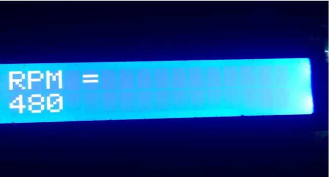
We are grateful to the authors of valuable research papers and books that we have used as reference for this project. To identify the rotation of the fan whose acceleration is being measured, here we have to use which consists of a component that plays the main role called a microcontroller, secondly an alpha-numeric LCD display and an IR sensor. The counted pulse reading is now displayed on the LCD screen in RPM which is revolutions per minute.
INTRODUCTION
- introduction
- Problem Statement
- Objective
- Objective of the project
- Scopes
- Methodology
- Organization of the Report
When the ebony tape surface is encountered by the infrared beam, transistor 2N3904 and both the phototransistor will turn off immediately. A digital tachometer can be designed in several ways, as the main control unit of the scheme here we choose this method. As the detection mechanism of the rotation of any axis, the infrared transmission mechanism is applied here.
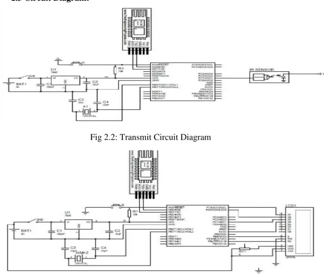
In this way, for each rotation of the shaft of any machine, it will send an output pulse. At the end of the process, the result of the rotation will be displayed in the alphanumeric LCD screen. The first chapter describes an idea about our project construction and design of wireless tachometer system, Brief description of the project, problem statement, scope and methodology.
SYSTEM REVIEWS
- Introduction
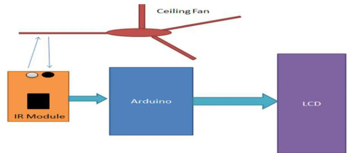
- General Block Diagram
- Description of Block Diagram
- Working Process
- Counting of the revolution per minute
- Regulating the speed of motor
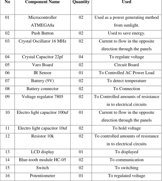
- List of Components used in Circuit
- HARDWARE AND
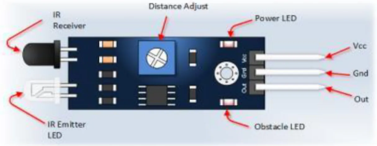
IR sensor module consists of detector infrared rays called photodiode and an IR transmitter. On the rotating object is glued a reflective pull-down which can be a disc or fan with an IR sensor. Passing the reflective extraction, the phototransistor receives the reflected wave coming from the IR sensor as IR waves.
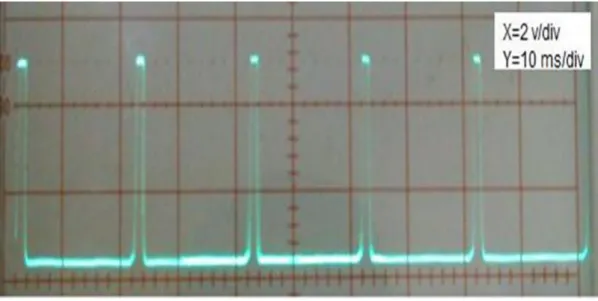
The conduction of the phototransistor is more than before at that time and the voltage across the 68K resistor increases at that time. The figure seen below is the waveform that we get from the above process result. At digital pin 2 of the ATMEGA8a, an emitter from the phototransistor is being attached.
In the emitter waveform shown above, there will be an interruption at each upper branch. The number of interrupts occurred in a given time is measured by incrementing a variant using the interrupt dwell routine. The Millis() functions are used to determine the time that is exceeded at the time of the count cycle.
At PWM pin 9 its base is attached to the ATMEGA8a care of the current gating R1 resistor. At analog pin A0 of the ATMEGA8a the wiper of the rabbit control R4 POT is attached. The program used to run digital tachometer using ATMEGA8a is attached at the bottom of the book.
Therefore, there will be a break in the transmitter waveform for each top shot.
COMPONENT DESCRIPTION
- Introduction
- Microcontroller ATMEGA8a
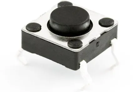
- Push Button
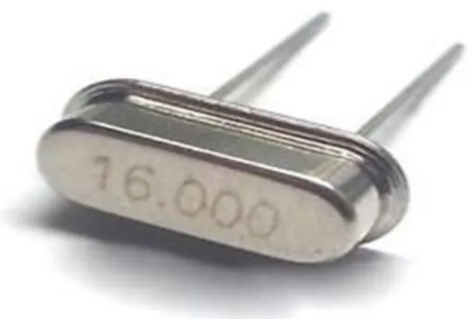
- Crystal Oscillator 16 MHz
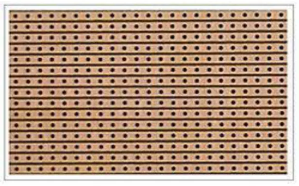
- Varo Board
- IR Sensor
- Working Principle of IR Obstacle Sensor
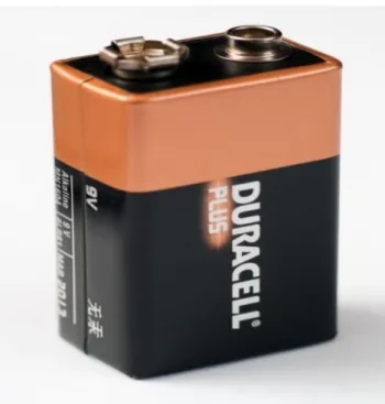
- Battery (9V)
- Voltage regulator 7805
- Working
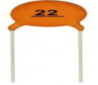
- Electrolytic capacitor 100 of 10uf
These different electrical characteristics of the ceramic capacitors should group them into "application classes". As of the year 2013, there were two groups of standards in use, one coming from the “International Electro Technical Commission (IEC)” and another coming from the now defunct “Electronic Industries Alliance (EIA)”. Ceramic capacitors, especially MLCCs (multilayer ceramic capacitors), are the most commonly made and used capacitors in electronic materials. The different ceramic materials used for ceramic capacitors, par-electric or ferroelectric ceramics, affect the capacitors' properties and electrical behavior.
In the early days, the first Vero board produces different wiring boards that are actually a prototype. If any obstacles have appeared in front of the sensor, they can be found out by a probe that uses IR energy to detect. The definition of IR emitter is an LED that can emit radiation that is infrared in nature.
The receivers are made in the form of a transistor known as a phototransistor and a light emitting diode known as a photodiode. The 9 volt battery, which is a common size and shape of battery that was pioneered by mainstream transistor radios. This format, which is mercury oxide batteries, has not been made for many years because of the content named mercury.
Most 9 volt alkaline batteries are made from 6 different 1.5 volt LR62 cells covered in a suitable casing. Here, we discuss about IC 7805. Voltage regulator IC 7805 is authentically a member of a 78xx number of voltage regulator ICs. The XX present in the 78xx represents the value of the tuned output voltage that the discrete IC provides.
The secondary of the transformer is also attached to the bridge rectifier (a dedicated IC or a stack of 4 1N4007 diodes can be used).
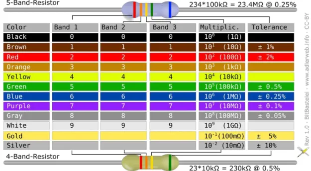
3.11 10k Resistor
- Resistor color code
- LCD Display
- Blue-tooth module HC-05
- Switch
- Potentiometer 10k
- Cost Analysis
- Cost Sheet
- Conclusion
Early 1920s is the time when the electronic color code was developed by the Radio Manufacturers Association (RMA). After this, another association called the Radio Electronics Television Manufacturers Association (RETMA) started to develop the color code. These standards define a letter and number code in integration with the color code for resistors and capacitors respectively.
Instead of a color code, resistance values are marked with alphanumeric codes printed on the surface. LCDs are widely available that display arbitrary images (as in a general-purpose computer display) or well-arranged images with low information content that can be exposed or invalidated, such as predefined words, numbers, and seven-segment display, as in a digital watch. The HC-05 Bluetooth module can be used in a Master or Slave configuration, making it an excellent solution for wireless communication.
This serial port Bluetooth module is fully qualified Bluetooth V2.0+EDR (Enhanced Data Rate) 3Mbps modulation with complete 2.4GHz radio transceiver and baseband. It uses CSR Blue core 04 external single chip Bluetooth system with CMOS technology and with AFH (Adaptive Frequency Hopping Feature). The Bluetooth module HC-05 is a MASTER/SLAVE module. Quantifying the instrument called a potentiometer is essentially a voltage divider used to quantify electrical potential (voltage); the components are an implementation of the same principle, hence its name.
Potentiometers are also commonly used electrical controls, devices such as volume controls on audio equipment. Potentiometers consist of a resistive element, a sliding contact (wiper) that moves along the element and thus makes good electrical contact with one of its parts, electrical terminals at each end of the element, a mechanism that moves the wiper also from one end, the other and the housing, which contains an element and a wiper. Many inexpensive potentiometers are made with a resistive element (B) assembled in an arc of a circle, usually a little less than a full turn, and a wiper (100) that slides over this element as it rotates and makes electrical contact.
In this system, five main components and a few tools are used for construction. This project is used to save energy and increase voltage.
SOFTWARE ANALYSIS
- Introduction
- Description of our Software
- The compiled window of my code is shown below
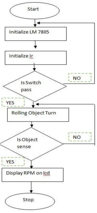
- Flow Chart of Diagram
With a C/C++ library called "Wiring", which makes many conventional i/p or o/p concepts very easily displayed via the ATMEGA8a IDE. Although users only need to define two functions to make a program executable, ATMEGA8a programs are implemented in C/C++,. A smart Fire base Data Recovery System is used by us in this application. Our design is very simple and it is easy to use for all customers.
Each grocery list is very easy to use and all data is stored in our database system.
RESULT AND DISCUSSIONS
- Calculated output
- Tachometer data Output
- Data output dc motor
- Proposed assembly for the wireless tachometer Transmitter system
- Proposed assembly for the wireless tachometer Receiver system
- Result
- CONCLUSION
- Conclusion of the project
- Advantages
- Disadvantages
- Future Scope
Here we can see that 1.01% is the error of our microcontroller predicted tachometer and 2.43% is the percent error of the existing tachometer. The major advantage is that no physical contact with the rotating shaft is required to quantify its speed. The IR LED emits infrared light to the rotating disk and the photodetection diode receives the reflected light beam.
This special arrangement of sensors is located about an inch away and faces the rotating disc. If the surface of the disc is rough and dark, the reflected IR light will be negligible. A scintilla of white paper glued to the rotating disk is just enough to reflect the incident IR light as it passes in front of the sensor, transpiring once per second. rotation (shown below).
If the entire disc surface is shiny and reflective, use a piece of ebony paper instead so that part will absorb the IR light once per spin. In both cases, a pulse will be generated at the output of the signal conditioning circuit for each complete rotation of the disc. A device used to measure the rotational speed of a shaft or disc is known as a tachometer or tachometer or tachometer.
It is an arbitrary combination that one is used for the engine in the automotive industry and the other for the speed of the vehicle. The termination of the emitter/detector circuit that sent +5v rising edge signals to the microcontroller is done by a fan. The LCD output of the same value from the rpm counter corresponded to the actual fan speed and was correct.
The disadvantage of this device is that it cannot work in daylight due to the sensors used instead of laser.
APPENDIX A