Design and Development of a Search and Rescue Robot
BY
Sabbir Ahmed Akkhar ID: 161-15-7534
Pranto Sharma ID: 161-15-7539 Mohammad Fahim Jamali
ID: 161-15-7545
This Report Presented in Partial Fulfillment of the Requirements for the Degree of Bachelor of Science in Computer Science and Engineering.
Supervised By
Mr. Md Abbas Ali Khan
Lecturer
Department of CSE
Daffodil International University Co-Supervised By
Mr. Md Sadekur Rahman
Assistant Professor Department of CSE
Daffodil International University
DAFFODIL INTERNATIONAL UNIVERSITY
DHAKA, BANGLADESH DECEMBER 2019
ii
©Daffodil International University
ACKNOWLEDGEMENT
First, we express our heartiest thanks and gratefulness to almighty Allah for His divine blessing makes us possible to complete this project successfully. We feel grateful to and wish our profound our indebtedness to, Mr. Md. Abbas Ali Khan Lecturer, Department of CSE, Daffodil International University, Dhaka. Deep Knowledge & keen interest of our supervisor in the field of wireless network influenced us to carry out this project. His endless patience, scholarly guidance, continual encouragement, constant and energetic supervision, constructive criticism, valuable advice, reading many inferior drafts and correcting them at all stage have made it possible to complete this project.
We would like to express our heartiest gratitude to other faculty member and the staff of CSE Department of Daffodil International University for their kind help to finish our project
We would like to thank our entire course mate in Daffodil International University, who took part in this discuss while completing the course work.
Finally, we must acknowledge with due respect the constant support and patients of our parents.
iii
©Daffodil International University
ABSTRACT
Embedded system as name suggest that it is combination of hardware and software systems.
Robot which is architecture of controller and embedded in particular system which is part of hardware and software system. In this project, proposed a system which could be implemented for the save people from earth quick or any kind of natural deserter if people stuck under the building or any kind of narrow place where a even human can‟t help them. IN 21th century everyone wants a safe life, but the natural disaster or unexpected dangers can harm people anytime.[1]If some people stuck in unexpected situation and its uneasy for them, its take time to find out them and their location and it could be very dangerous for their health someone could die. This robot and go into the very narrow or destroyed place and detected human and give the location of victim and it save time and the life of the victims. By two way this robot could controlled by the octomoms system using its sensors and a wireless Android based application.
Its transited data via Bluetooth and it‟s also give the video stream of the work field. In this project I used two Arduino microcontrollers.
iv
©Daffodil International University
TABLE OF CONTENTS
CONTENTS PAGE
Approval i
Board of examiners i
Declaration ii
Acknowledgements iii
Abstract iv
List of Figures v-ix
CHAPTER
CHAPTER 01: INTRODUCTION 1-2
1.1Introduction 1
1.2Motivation 2
1.3Objective 2
1.4Expected Outcome 2
CHAPTER 02: BACKGROUND 3-4
2.1Related Work 3
2.2Scope of the problem 4
2.3 challenges 4
v
©Daffodil International University
CHAPTER 03: ROBOTICS SYSTEM WORKFLOW 5-8
3.1Introduction 5
3.2Sensors 6
3.3Sensors 7
CHAPTER 04: ANALAYSIS OF THE SYSTEM COMPONENTES 9- 15
4.1List of The Components 9
4.2Describe Following 10
CHAPTER 05: DEVELOPMENT 16-23
5.1Software Part 16
5.2Front-end Design of Android application 16
5.3Front-End Design of Robot 17
5.4Back-End Deign of Arduino IDE (Program the Robot) 19
5.5Camera Webserver with Arduino Uno 20
5.6Circuit Diagram 22
5.7Android Application Back-End 23
CHAPTER 06: CONCLUSION AND FUTURE WORK 24
6.1Future work 24
6.2Conclusion 24
vi
©Daffodil International University
REFERENCES 25
APPENDICS 26-27
Appendix A: project reflection 26
vii
©Daffodil International University
LIST OF FIGURES
FIGURES PAGE NO
Figure 2.1.1: USAR Robot of CMU 3
Figure 2.1.2: Packo after World Trade Centre disaster 4
Figure 3.1.1: Business model Diagram 5
Figure 3.2.1: Use Case 6
Figure 3.3.1: Working process of Ultrasonic Sensor 7
Figure 3.3.2: Working process OF PIR 8
Figure 4.2.1: Arduino Microcontroller MEGA 256 10
Figure 4.2.2: Arduino UNO Microcontroller 11
Figure 4.2.3: HC-05 Bluetooth module 12
Figure 4.2.4: Buzzer 12
Figure 4.2.5: Motor Driver 13
Figure 4.2.6: EPS 32 CAM 13
Figure 4.2.7: 1500mah Lipo Battery 14
Figure 4.2.8: 6F22 9v Battery 14
Figure 4.2.9: Arexx RP-5 Robot Tank Chassis 15
Figure 5.2.1: Android application Front-end View 16
Figure 5.3.1: Robot Front-end View 17
Figure 5.3.2: Robot Front-end View 18
Figure 5.3.3: Robot Front-end View 18
Figure 5.4.1: PIN mode Define and Define Components 19
Figure 5.4.2: Define condition to avoid obstacles 19
©Daffodil International University
viii
Figure 5.5.1: Pin mode Define and Define Components 20
Figure 5.5.2: Camera Server Setup 20
Figure 5.5.3: Esp 32 Cam Stemming 21
Figure 5.5.4: Esp 32 Camera Index 21
Figure 5.6.1: Circuit diagram for 1st part 22
Figure 5.6.2: Circuit diagram for 2nd part 22
Figure 5.7.1: Android application Back end work used Android Studio 23
Figure A.1: Pin Input and Output 26
Figure A.1.1: Check Front Distance 26
Figure A.2: Application View 27
©Daffodil International University
ix
CHAPTER 01 INTRODUCTION
1.1 Introduction
Before 250 B.C a Greek inventor and mathematician Ctesibius invented „Clepsydra or Water clock‟ that was one of the first robot. Earliest 1890‟s Nikola Tesla build a „remote control vehicle‟, Tesla is best known as inventor of A.C electrical power, radio, induction motor and others electronics devices. The first industrial robot ware probably „Unimates‟ created by George Devol and Josephe Engleberger between 1950, s to 60‟s. Eagleburger started the first robotics company, called „Unimation‟, and called him as a „father of Robotics‟.
After Eagleburger creation expectation of robotics field increases of multiple sector. Living 21‟st century without advanced technology life will be stationary, peoples are depending on technology, robots, thinking for human alternatives. Being thought IoT, Robotics, AI, Machine Learning are the structure of future technology. Embedded system and Robotics are the most effective field for modern technology, we know that embedded system is a programmed controlling and operating system with a dedicated function.[1] Combination of embedded system and robotics get real life workable engine or device. That engine or device could be operated by automatically or manually or using by command.
Now we can talk about modern and future era of Robotics, Robot will simply replace people on the job in fact then can essential for us, if we see the Amazon Echo Smart Speaker that incredible device are combination of embedded system so on, robotics and AI, everyone knows about human robot Sophia, using robot for every sector are increasing, for industrial purpose implementation of robots are increasing even they thinking about for robot workers which alternative for humans. Everything is for better living life , safety is the main expectation of everyone daily life, earth quick or apartment disaster for lake of soil test or planning many people lose their life this, our robot can safe many time to find out their location and its help to safe their life and the life risk of the risqué team .
1
©Daffodil International University
1.2 Motivation
▪
Currently, in our country we are facing some violence (terrorist) activity.
▪
Police, RAB, Army (SWAT) are trying to trace the correct location of the terrorist and try to arrest them even risking their life.
▪
On 24 April, 2013, Rana plaza tragedy which was a structural failure and 1134 people were death. Approximately 2,500 injured people were rescued from the building alive.
1.3 Objective
▪
This robot can save people from earth quick or any kind of natural deserter if people stuck under the building or any kind of narrow place where a even human can‟t help them.
▪
This robot also can save the life of army in battle field to trace the location and information of enemy.
▪
The feature of its camera, the robot can save people‟s life from terrorist attack or can count how many of enemy are there and also can trace which kind of weapon are using inbattlefield
1.4 Expected Outcome
▪
Our robot will be controlled by warless based on Android Application and it also make its own path is its need by sensors what we used.
▪
When the controller connected the robot to the application via Bluetooth and then its go the incident field and send data (VIDEO STREAM).
▪
When the robot finds the human send the application massage (HUMAN DECTED).
▪
This robot also uses in national security to get the Enemies position free of danger and safely.
▪
This system can work in night vision.
▪ It‟s mainly saved time to rescue or find out people passion.
2
©Daffodil International University
CHAPTER 02 RELATED WORK
2.1 Related Work
Natural disasters are often inexorable in most of the parts of the world, especially in Japan and USA. However, these two places are also renowned for their technological advancements and are hotbeds of robotic engineering and thus it is fair to assume that this is a well-researched topic in such areas.
▪
USAR (Urban Search and Rescue Robot): National Science Foundation funded Carnegie Mellon University, Pittsburgh to explore the use of autonomous robots in rescue research.
proposed necessary modifications in 2004 to the USAR built earlier by Carnegie Mellon researchers which was capable to navigate difficult terrain but lacked sensors for detection.
The robot consists of two-bicycle wheels and uses differential drive by altering speed of the left and right wheels, thereby assisting it to climb small obstacles. The wheels are controlled by PID that allows it to climb ramps and slopes. However, it is incapable of climbing stairs and cannot return back to position when overturned. Furthermore, it is much larger than our Rescuebot making it difficult to pass through narrow spaces and to break-away when trapped. For sensors, USAR uses pyroelectric sensors, USB camera, microphone and IR camera to perceive existence of life. [3].
Figure 2.1.1: USAR Robot of CMU [3]
3
©Daffodil International University
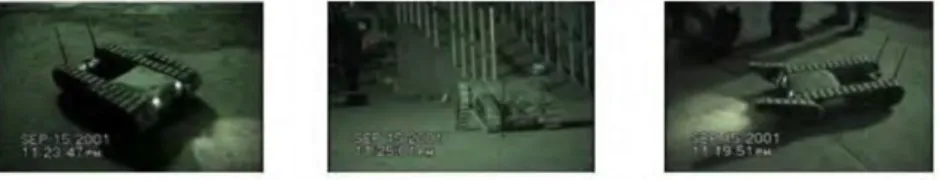
▪
CRASAR (Centre of Robot-Assisted Search and Rescue): University of South Florida constructed a robot in 2001 and according to [3] the robot is able to provide an overview of the place that the workers cannot reach. This robot was first used in the World Trade Centre Disaster in 2001.[3] It uses different detectors like millimeter wave radar for measuring distance, a camera for vision, a forward-looking infrared camera (FLIR) for the human heat detection and an SpO2 sensor to measure the oxygen quantity in blood. Using this, the user can figure if the victim is alive. The robot is entirely human controlled and sends information to the user per requirement.
Figure 2.1.2: Packo after World Trade Centre disaster 2.2 Scope of the problem
In our project first we plane what we are going to make. After decided we find the obstacles, we fin may problems which we will face on, some problem what we predict:
▪
Selection of the mother board.
▪ PIR sensor work purpose.
▪ Vehicle design.
▪ Power distribution.
2.3 Challenges
we face many challenges, it took 9 months to make our robot work properly. But our team know it‟s very obvious to face challenges, at last we make this with full of Confidence. Some Big challenges we faced.
▪ Short circuit & Circuit design.
▪ Circuit design.
▪ Vehicle design for every kind of surface it can run.
▪ We face a big problem to find the IP based camera for warless video streaming.
▪
Our robot chasses are compact to fit the components but it was difficult to design the robot very strong for outside effects.
4
©Daffodil International University
CHAPTER 03
HOW OUR ROBOTICS SYSTEM WORKS
3.1 Introduction
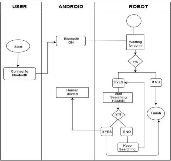
We have been developing our search and rescue robot for saving people if they get stuck in life threatening situation. Rescue team came to the incident field and start the robot and send the robot and they controlled from outside when the robot finds human then it sends data to the android application which is connected to the robot. In that place the robot finds human it will be stopped and create Buzzer sound to track the real place.
Figure 3.1.1: Business model Diagram
5
©Daffodil International University
3.2 Use Case
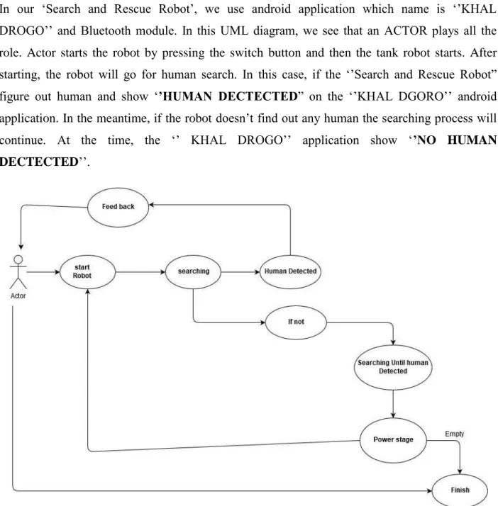
In our „Search and Rescue Robot‟, we use android application which name is „‟KHAL DROGO‟‟ and Bluetooth module. In this UML diagram, we see that an ACTOR plays all the role. Actor starts the robot by pressing the switch button and then the tank robot starts. After starting, the robot will go for human search. In this case, if the „‟Search and Rescue Robot”
figure out human and show „’HUMAN DECTECTED” on the „‟KHAL DGORO‟‟ android application. In the meantime, if the robot doesn‟t find out any human the searching process will continue. At the time, the „‟ KHAL DROGO‟‟ application show „’NO HUMAN DECTECTED‟‟.
Figure 3.2.1: Use case
6
©Daffodil International University
3.3 Sensors
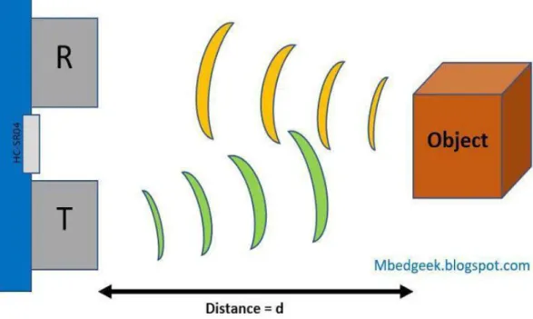
Ultrasonic Sensor: As sensor the Ultrasonic sensor it the best option and sense high level reliability. An ultrasonic sensor is an instrument that measure the distance of an object using ultrasonic sound wave.
Calculation of the Distance
In our module ultrasonic sensor calculate the distance:
L=1/2*T*C Here,
L= The distance
T= Is between the emission and reception time C= Is the sonic speed
(The value is multiplied by 1/2 because T is the time for go-and-return distance.)
Figure 3.3.1: Working process of Ultrasonic Sensor
7
©Daffodil International University
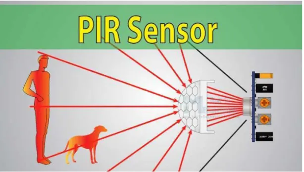
Passive Infrared Sensor (PIR): PIR sensor is a sensor that detect human moving approximately 10m from the sensor. The actual distance range is to 5m to 12m.
Figure 3.3.2: Working process OF PIR
8
©Daffodil International University
CHAPTER 04
ANALAYSIS OF THE SYSTEM COMPONENTES
4.1 List of The Components
▪
Microprocessor
1. Arduino Mega 2560.
2. Arduino Uno.
3. ESP 32 CAM Board.
▪
Sensors
1. Ultrasonic Sensor HC-SR04 2. PRI
3. Camera (ESP 32 CAM)
▪
Motors
1. DC motor 2. Motor Driver
▪
Power
1. 1500mah lipo battery.
2. 6F22 9v battery.
▪
Body1. Damping Balance Tank Robot Chassis.
▪
Connections 1. Jumper Wires▪
Lights
1. Two red led light(back).
2. One head light(front).
9
©Daffodil International University
4.2 Describe Following
Arduino Microcontroller MEGA 2560
Arduino mega is a microcontroller board on ATmega2560. It has 54 input and output pin (14 pins can be use in PWM output). It has power Jack, reset button, USB connection, an ICSP header, AC and DC adapter and or battery to get started. In our project we use this board to control the robot wheel and abstracted detector. the Bluetooth on this board connect the Android application. The PIR sensor also connected on this board. It supplies 5v to the all components attested on this board [5]
Figure 4.2.1: Arduino Microcontroller MEGA 256[5].
Arduino Microcontroller
For this project used Arduino UNO microcontroller, UNO Rev3 is a ATmega328P microcontroller board based, an 8bit microcontroller with 32kb flash memory and 2kb RAM.
UNO contains everything needed to support as microcontroller, simple connection it to a computer with USB cable, Arduino board has analogue and digital both of pins. Uno is open- source hardware, for import the software code use IDE. If we see the technical specifications- microcontroller is ATmega328, this operate voltage 5V, Input voltage(recommended) 7-12V and
10
©Daffodil International University
Input voltage(Limit)6-20V, Digital I/O Pins is 14, PWM Digital I/O Pins is 6, Analog Input Pins is 6, DC current per I/O pin 40mA, DC current for 3.3V 50mA, Flash memory 32kb, SRAM 2kb, EEPROM 1kb, Clock Speed- 16MHz,.
Figure 4.2.2: Arduino UNO Microcontroller [5]
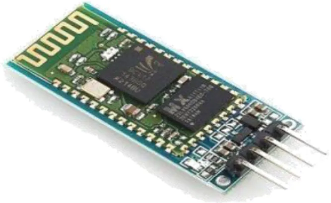
Bluetooth Module
HC-05 Bluetooth module used for this project. Communicate between android device and robot Bluetooth module will work for medium. Bluetooth specifications is: Bluetooth protocol- Bluetooth specification v2.0+EDR, frequency 2.4GHz ISM band, sensitivity- <= -84dBm at 0.1% BER, speed- asynchronous: 2:1mbps (Max) / 160 kbps, Synchronous: 1mbps/1mbps, Security- Authentication and encryption, power supply: +3.3V DC 50mA, working temperature:
-20 ~ +75 centigrade, Dimensions: 15.2*35.7*5.6mm.For this project with any Bluetooth support device could be communicate with this HC-05 Bluetooth module.
11
©Daffodil International University
Figure 4.2.3: HC-05 Bluetooth module
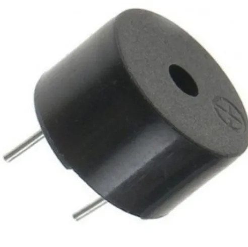
Buzzer
Buzzer is like alarming device; buzzer is use for alert in something. In our project when our robot finds Human the buzzers will make sound in that place for find the exactly that place.
Buzzer make a very important part.
Figure 4.2.4: Buzzer
Motor Driver
Control motors with Arduino you don‟t need to spend a lot of money, with many motor shield select the L298N H-bridge IC that can allows you to control the speed and also direction of two DC motors Need Arduino microcontroller, DC power supply 7-35V .The Motor driver is also programed for the wheel control ,how the robot go ahead or turned around .
12
©Daffodil International University
Figure 4.2.5: Motor Driver Eps 32 Cam
ESP 32 cam is a small size camera module and its low power consume device. this device is very easy easy to use in IOT project. we use this module to send video Stream to the android application Via Wi-Fi in 100-meter area.
Some features of ESP 32:
1. Support WIFI And Bluetooth.
2. OV2640 Camera with Flash.
3. SD Card Slot to Save Data.
Figure 4.2.6: EPS 32 CAM
13
©Daffodil International University
1500mah Lipo Battery
LiPo batteries exist in cells, each LiPo cell has a nominal voltage of 3.7V. If higher voltage is required, these cells can be connected in series to form a single battery.
Figure 4.2.7: 1500mah Lipo Battery
6F22 9v Battery
The nine-volt battery, or 9-volt battery, is a common size of battery that was introduced for the early transistor radios.
Figure 4.2.8: 6F22 9v Battery
14
©Daffodil International University
Body
The Arexx RP-5 Robot Tank Chassis is a tank track style base that is an ideal base for building mobile robots. The chassis has built-in motors and gearboxes which you can easily interface with PICAXE, GENIE, Arduino or any other microcontroller system, as well as radio control systems.
Some features of Robot Tank Chassis:
1. Dimensions: 175 X 135 X 60mm.
2. 2x 280 Type Motors.
3. 80:1 Gear Ratio.
4. Rubber Tank Tracks.
5. 6x AA Battery Holder Included.
6. It Can Go on Any Kind of Obstacles.
7. It‟s Very Strong and Less Damageable.
Figure 4.2.9: Arexx RP-5 Robot Tank Chassis
15
©Daffodil International University
CHAPTER 05 DEVELOPMENT
5.1 Software part
1. Arduino IDE (program the Robot).
2. Android Studio (For make the Android Application).
5.2 Front-end Design of Android application
For wireless connection we made an android application for start the robot, connect the Bluetooth, detection data, and also for the live video stemming view. We deigned the application use Android Studio.
1st part 2nd part 3rd part
Figure 5.2.1: Android application Front-end View
This application can be installed in any android devise and anyone can use this very easily. In 1st part just open the application after that just connected the Bluetooth and send the robot in the field and last part when the robot find the human it will send a massage in application HUMAN DETTED.
16
©Daffodil International University
5.3 Front-end Design of Robot
The robot is made from 15 other components which are mentioned in hardware part after the all connation it look like.
Figure 5.3.1: Robot Front-end View
17
©Daffodil International University
Figure 5.3.2: Robot Front-end View
Figure 5.3.3: Robot Front-end View
18
©Daffodil International University
5.4 Back-end Deign of Arduino IDE (program the Robot)
We Insert All Program To Arduino Via Arduino IDE.Here We Define Our All Component In Arduino And Pin Mode. Which Pin Will Give Us Input And Which Will Give Output.
Figure 5.4.1: Pin mode Define and Define Components.
Figure 5.4.2: Define condition to avoid obstacles
19
©Daffodil International University
5.5 Camera Webserver with Arduino Uno
Figure 5.5.1: Pin mode Define and Define Components
Figure 5.5.2: Camera Server Setup
20
©Daffodil International University
Out Come of Video Stream
Figure 5.5.3: Esp 32 Cam Stemming
Figure 5.5.4: Esp 32 Camera Index
21
©Daffodil International University
5.6 Circuit diagram
We use mainly two board for our robot. The two robots work one think but, in its body, the two board make the full process in two process (1) controlling the vehicle and decent human use sensor. (2) this board give the video streaming to the android application.
Figure 5.6.1: Circuit diagram for 1st part [4]
Here we use Arduino Mega as a Microcontroller board, 3 Ultrasonic sensor,2 buzzer, Motor driver with two DC motor, One PIR sensor and the power comes from 1500 lipo battery.
Figure 5.6.2: Circuit diagram for 2nd part [4].
22
©Daffodil International University
Here in 2nd part we the Arduino UNO with ESP 32 CAM set, OV 2640 camera (2 MP), tree LED light for dark mode and for power supply 1500 lipo battery.[6]
5.7 Android application Back-End
In our system, we connect between system and apps by using Bluetooth. In this android apps we use java programming language. Use “BLUETOOTH-SOCKET” is add for make configure between Bluetooth and BT hardware.
To receive data form robot BT in our application we use „‟INPUT STREEM‟‟ and caught the data in ‟‟BYTE STREEM‟‟ though „‟BUFFER READING‟ ‟Here, if our “PIR” sensor detected any human it will sent [„1‟] as parameter and the apps transform it to string “HUMAN DETECTED”. For sending data we use “output stream”. all those functions are activities errors handled by” TRY CASE” method.
Chapter 06
Conclution and future work
Figure 5.7.1: Android application Back end work used Android Studio.
23
©Daffodil International University
CHAPTER 06
Conclusion and Future work
6.1 Future work
1. Future scope of this robot to add night vision camera for finding people easily in dark zone.
2. Future scope to add robotic hand to carry daily needed item (water, food, fruits so on).
3. To add image classification for difference between any type human and other (cat, dog, stone).
4. In this time, we use normal chassis in our project but future scope to add steel body chassis.
5. Future scope to a add 9mm GLOCK 26 pistol capable for protect and rescue victim by shooting the criminal.
6. Future scope to add caterpillar tracks that allow it to climb over obstacles and travel in difficult terrain.
7. Future scope to add GPS sensor.
8. Future scope to add IR sensor for motion detection [3]
6.2 Conclusion
In our search and rescue robot mainly made for defensive people. Anyone means defense member and ordinary people can easily control the robot. Now-a-days we find most robots working for people in industries, factories. For instance, our robot is mainly help defense people to figure out criminal, the people who stack into the damage building. We can also use this robot in our national security, if police need to track some victim house or some place without any casualties. At last we say this robot is for save people life. we spend our may time and money to build this project.
24
©Daffodil International University
REFFERENCESS
[1] dspace.daffodilvarsity.edu.bd, available at << http://dspace.daffodilvarsity.
edu.bd:8080/handle/123456789/2463>>, last accessed on 28-10-2019 at 1.35 am
[2] dspace.daffodilvarsity.edu.bd, available at << http://dspace.daffodilvarsity.
edu.bd:8080/handle/123456789/2217>>, last accessed on 27-10-2019 at 11.56 am
[3] dspace.bracu.ac.bd/available at << http://dspace.bracu.ac.bd/xmlui/handle/10361/4348>>, last accessed on 16-10-2019 at 3.48 pm
[4] circuito.io, available at <<https://www.circuito.io/ >>, last accessed on 30-10-2019 at 5.39 pm
[5] store.arduino.cc, available at << https://store.arduino.cc/usa/mega-2560-r3>>, last accessed on 30-10-2019 at 6.18 pm
[6] randomnerdtutorials.com, available at << https://randomnerdtutorials.com/esp32-cam-video- streaming-face-recognition-arduino-ide/ >>, last accessed on 19-10-2019 at 2.26 am
25
©Daffodil International University
APPENDICES
APPENDIX A: PROJECT REFLECTION
1.
Ultrasonic Sensor, PIR, Motor Driver Based Code with Arduino Mega 256:Figure: A.1 Pin Input and Output
Figure: A.1.1 Check Front Distance
26
©Daffodil International University
2.
Android Apps View:Figure: A.2 Application View
27
©Daffodil International University
©Daffodil International University
![Figure 2.1.1: USAR Robot of CMU [3]](https://thumb-ap.123doks.com/thumbv2/filepdfnet/10816693.0/13.918.190.720.782.975/figure-2-1-1-usar-robot-of-cmu.webp)
![Figure 4.2.1: Arduino Microcontroller MEGA 256[5].](https://thumb-ap.123doks.com/thumbv2/filepdfnet/10816693.0/20.918.109.804.390.748/figure-4-2-1-arduino-microcontroller-mega-256.webp)
![Figure 4.2.2: Arduino UNO Microcontroller [5]](https://thumb-ap.123doks.com/thumbv2/filepdfnet/10816693.0/21.918.152.767.243.543/figure-4-2-2-arduino-uno-microcontroller-5.webp)