Fig.3.2 SEM photographs of grinding chips under dry, wet and MOL conditions at 10I'm feed during grinding. Fig.3.3 SEM photographs of grinding chips under dry, wet and MOL conditions at 20I'm feed during grinding. Fig.3,4 SEM photographs of grinding chips under dry, wet and MOL conditions at 30I's introduction during grinding.
Fig.3.5 SEM photographs of chip grinding under dry, wet and MOL conditions at 40I'm input during grinding. Fig.3.6 SEM photographs of chip grinding under dry, wet and MOL conditions at 10I'm input during grinding. Fig.3.7 SEM photographs of chip grinding under dry, wet and MOL conditions at 20I'm input during grinding.
Figure 3.B SEM photographs of chip grinding in dry, wet and MOL conditions at 30 I feed during grinding. Figure 3.11 Variation of the temperature of the grinding zone with feeding in dry, wet and MOL conditions during grinding.
ChaPter-1
Introduction
The grinding process is mainly characterized by high specific energy demand due to the large negative rake and high cutting speed, which results in very high temperature. Residual tensile stresses, if present in the soil sample, result in reduced static and dynamic strength and corrosion resistance, and lead to distortion immediately after processing and service life. Residual tensile stress also causes surface and subsurface microcracks, especially in the case of brittle materials.
Another obvious problem when grinding ductile and sticky materials is wheel loading, mainly due to the accumulation of chip particles in the grit spaces. In addition, wheel loading also causes increases in forces, temperature and vibrations, poor surface finish, redeposition, poor surface integrity etc. It seems that the high temperature in the grinding zone is the main problem and therefore methods have been tried over the years to address this to grab. problem.
Application of proper grinding fluids at times has reduced the above problems to some extent by cooling and lubrication of the grinding zone. The application procedures of these fluids are usually by flood cooling or in the form of jet or even mist.
Survey of the previous work
- Mechanism of chip formation and chip characteristics
- Control of grinding temperature
- Characteristics of ground surface
- Summary of the review
They suggested that the high number of spherical chips indicates heavy friction of the wheel with the workpiece. Kops and Shaw [1982J identified temperature in the grit, surface and subsurface of the workpiece as related to;. 1982] estimated temperature field and its history at the surface and subsurface of the workpiece using the finite element method.
The variation in the thermal properties of the work material with temperature was taken into account. Howes [1990] reported that the lubricating and cooling properties of the grinding fluids directly affect the surface integrity of the workpiece. Marshail and Shaw [1952] described burning as the appearance of the temper color on the soil surface due to high temperatures.
The normal and tangential forces and their ratio suddenly increase at the beginning of combustion. The dimensional accuracy and surface integrity of the workpiece is also degraded due to high temperature.
Objectives of the Present Work
ChaPter-2
Introduction
In this regard, it has already been observed through previous research that the proper application of MOL can play a vital role in providing not only environmentally friendly, but also some techno-economic benefits.
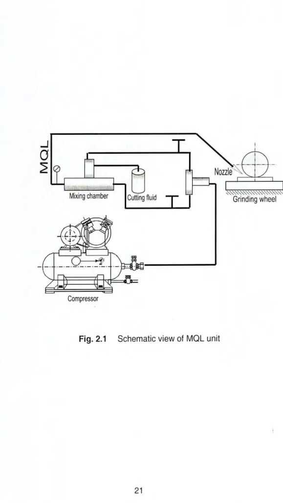
Design and Fabrication of the MQL Delivery System
The concept of minimum quantity lubrication, sometimes referred to as near-dry lubrication or microlubrication, has been suggested as early as a decade ago as a means of addressing environmental interference issues and occupational hazards associated with airborne cutting fluid particles on shop floors. of the factory. Minimizing cutting fluid also leads to economic benefits by saving lubricant costs and workpiece/tool/machine cleaning cycle time. The compressor supplies the high pressure air (3.5 bar) and the pump supplies the cutting fluid (200 ml/hour) from the cutting fluid reservoir tank.
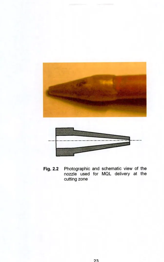
Air and cutting fluid are mixed in a mixing chamber so that the mixture contains the minimum amount of lubricants (MOL). The mixture of cutting fluid and air (MOL) is impinged at a high velocity through the nozzle at the chip tool interface.
Design and Fabrication of the Nozzle
ChaPler-3
Experimental Procedure and Conditions
Again, the cutting temperature is further increased by increasing the strength and hardness of steels for more specific energy requirements. Considering these facts, commonly used steels such as 42CrM04 steel and 16MnCr5 steel were used for these investigations. The position of the nozzle tip relative to the sanding plate was determined after many trials.
The MOL beam is directed in such a way that it reaches the grinding wheel and workpiece interface.
Experimental Results
- Microscopic study of the chips
- Grinding temperature
- Surface roughness
Fig.3.2 SEM photographs of particle gratings in dry, wet and MOL conditions at 10 IJrnin fed during grinding of 42CrMo4 steel. Fig.3.3 SEM photographs of grates under dry, wet and MOL conditions at 20 IJrn feed during grinding of 42CrMo4 steel. Fig.3.5 SEM pictures of chip grinding in dry, wet and MQL conditions at 40 ~ m infeed while grinding 42CrMo4 steel.
Figure 3.6 SEM photographs of chip grinding in dry, wet and MOL conditions at 10 J.lrn feed during grinding of 16MnCr5 steel. Figure 3.7 SEM photographs of chip grinding in dry, wet and MOL conditions at 20 IJmin feed during grinding of 16MnCr5 steel. Figure 3.8 SEM photographs of chip grinding in dry, wet and MOL conditions at 3D ~m feed during grinding of 16MnCr5 steel.
Fig.3.9 SEM photographs of grinding discs under dry, wet and MQl conditions at 40 11m input while grinding 16MnCr5 Steel. The temperature of the grinding surface was measured by simple technique using a constantan wire fitted in a thin slot provided by thread cutting at the middle portion of the work samples as indicated in Fig.3.10. Fig.3.11 and Fig.3.12 show the variation of the milling zone temperature observed in different environments at various inputs.
Figure 3.11 Temperature variation of the grinding area with feed in dry, wet and MOL conditions during grinding of 42CrMo4 steel. Figure 3.12 Change in temperature of the grinding zone with feed in dry, wet and MOL conditions during grinding of 16MnCr5 steel. The grinding characteristics of any material for any given wheel conditions and grinding process are also evaluated by the topography of the ground surface.
Surface characteristics include general textures, plastic deformation of bumps, oxidations and cracks, etc. The surface roughness of the milled samples was measured in transverse directions with a Talysurf (Surtronic 3+ roughness tester, Rank Taylor Hobson, UK) as shown. in Figure 3.13. Figures 3.14 and 3.15 show the variation of surface roughness observed in different environments at different feeds.
Fig.3.14 Change in surface roughness with indentation in dry, wet and MOL conditions during grinding of 42CrMo4 steel. Change in surface roughness with indentation under dry, wet and MOL conditions during grinding of 16MnCr5 steel.
ChaPter-4
Grinding Chips
At higher feeds of 30 pm and 40 pm, dry grinding produced almost similar types of chips suggesting similar mechanism of chip formation. Under wet grinding at the higher 30 pm and 40 pm inserts, the chips on their backs acquired a smooth appearance with central ridges produced by the top of the grates and the upper lamellar surfaces. Minimum quantity lubrication (MOL) on the other hand, provided small crushed chips also along with long lamellar chips, which indicate that cutting and breaking are the main chip formation mechanisms under such MOL conditions.
By studying the chip properties, it is clear that the mechanism of chip formation in dry and wet grinding is primarily shearing, plowing and rubbing. However, no indication was obtained regarding the change in the chip formation mechanism with the increase in feed. The chips obtained during grinding of 16MnCr5 steel at different feeds under different environments are shown in the figures from Fig.3.6 to Fig.3.9.
In the case of 16MnCr5 steel, spherical chips were almost absent in all environments, although all other types of chips were obtained especially in dry and wet grinding. This shows that here, too, the mechanism of chip formation is mainly shearing, plowing and rubbing. However, if we compare the images from fig.3.2 to fig.3.5 with the photos of 16MnCr5 steel chips (fig.3.6 to fig.3.9), it seems that the size of lamellar chips has decreased, which can be attributed to the greater hardness of 42CrM04 steel compared to steel 16MnCr5.
The number of broken chips also increased significantly in the case of 42CrM04 steel compared to 16MnCr5 steel under MOL condition. This indicates that under MOL grinding the mechanism of chip formation shifts further from shearing to breaking with increase in the work hardness. It was also observed that the sizes of the lamellar chips under MOL condition are smaller than those obtained under dry and wet milling.
Cutting Temperature
A simple technique using a constantan wire fitted into a thin slit provided by threading all the middle portion of the work samples was used to measure the grinding zone temperature. The experimental results shown in the Fig.3.11 and Fig.3.12 clearly indicate that the grinding zone temperature decreases due to minimum amount of lubrication. It is also noted that the cooling capacity of the MOL becomes higher at larger inputs.
Whereas, the cooling ability of the soluble oil has been rather poor and further decreased with the increase in feed, possibly due to its inability to reach the milling zone and film boiling at elevated temperature.
Surface Roughness
This can obviously be attributed to the lower temperature, the sharpness of the retained grit and less friction and plowing in MOL grinding.
ChaPler-5
MOL provided relatively more surface roughness compared to dry grinding, but lower compared to wet grinding, for less plastic deformation and friction, shear and fracture modes of chip formation, and retention of grain sharpness.
ChaPler-6