Once the route is established, all packets between a pair of communicating parties follow the same route through the network. A virtual circuit network is a cross between a circuit switched network and a datagram network. In Global Addressing, a source or a destination must have an address that can be unique within the scope of the network or internationally if the network is part of an international network.
SVCs are often called a dial-up service because the SVC is SVCs are often called a dial-up service because the SVC is established and terminated just like a telephone call. Before Frame Relay, some organizations used a virtual-circuit s it hin net ork alled X 25 that performed s it hin at the switching network called X.25 that performed switching at the network layer. X 25 has its own network layer This means that the user's data X.25 has its own network layer.
This means it can be easily used as a backbone network to provide p-services to protocols that already have a network layer protocol, such as the Internet. Frame Relay allows a frame size of 9000 bytes, which is suitable for all local area network frame sizes. Frame Relay is designed in this way to provide high-speed transmission capabilities for more reliable media and for higher-layer flow and error control protocols.
A virtual circuit in Frame Relay is identified by a number called a data link connection identifier (DLCI).
Frame Relay Layers
Frame Relay Frame
Extended address (EA) - The extended address (EA) bit indicates whether the current byte is the last byte of the address. An EA of 0 means there is another address byte to follow, an EA of 1 means the current byte is the last. Forward Explicit Congestion Notification (FECN) - The Forward Explicit Congestion Notification (FECN) bit can be set by each switch to indicate.
Backward Explicit Congestion Notification (BECN)‐p g ( ) The Backward Explicit Congestion Notification (BECN) bit is set (on frames traveling in the other direction) to indicate a congestion problem in the network. De-Eligibility (DE)- The De-Eligibility (DE) bit indicates the priority level of the frame. When set (DE= 1), this bit tells the network to drop this frame if it is congested This bit can be set to either to drop this frame if it is congested.
This bit can be set either by the sender of the frame (the user) or by any switch on the network.
Congestion Control in Frame Relay
Congestion Avoidance- To avoid congestion, the Frame Relay protocol uses 2 bits in the frame to explicitly warn the source and destination of the presence of congestion. BECN‐ The Backward Explicit Congestion (BECN) bit warns the sender of congestion in the network. The switch can use response frames from the receiver (full-duplex mode), or thep ( p ), switch can use a predefined connection (DLCI =1023) to send special frames for this specific purpose.
FECN‐ The FECN bit (forward explicit congestion notification) is used to warn the receiver about congestion in the network. However, the Frame Relay protocol assumes that the sender and receiver communicate with each other and uses some form of higher-level flow control. For example, if there is an acknowledgment mechanism at this higher level, the receiver can delay the acknowledgment, thus forcing the sender to slow down, delay the acknowledgment, thus forcing the sender to slow down.
Frame Relay vs. T‐line Network
Asynchronous Transfer Mode (ATM)
ATM Protocol Architecture
The protocol architecture shown in Figure 11.1 illustrates the basic architecture of a user-network interface. The ATM layer defines the transmission of data in fixed size cells and defines the use of logical connections. The use of ATM creates the need for an adaptation layer to support information transfer protocols that are not based on ATM.
AAL maps upper layer information to ATM cells that are transmitted over the ATM network, and then collects information from ATM cells for delivery to higher layers. Management plane:Management plane: Includes the management of the plane that performs the management functions related to the system as a whole and ensures coordination among all the planes, and the management of the layer that performs the management functions related to.
ATM Architecture
Connectivity between two endpoints is achieved through transmission paths (TPs), virtual paths (VPs), and virtual circuits (VCs). A transmission path (TP) is the physical connection (wire, cable, satellite, and so on) between an endpoint and a switch or between two switches. All cells belonging to a single message follow the same virtual circuit and remain in their original order until they reach their destination.
The first two VCs appear to share the same virtual path from switch I to switch III, so it is reasonable that these two VCs are joined together to form a VP. On the other hand, it is clear that the other two VCs share the same path from switch I to switch IV, so it is also reasonable to combine them to form a VP.
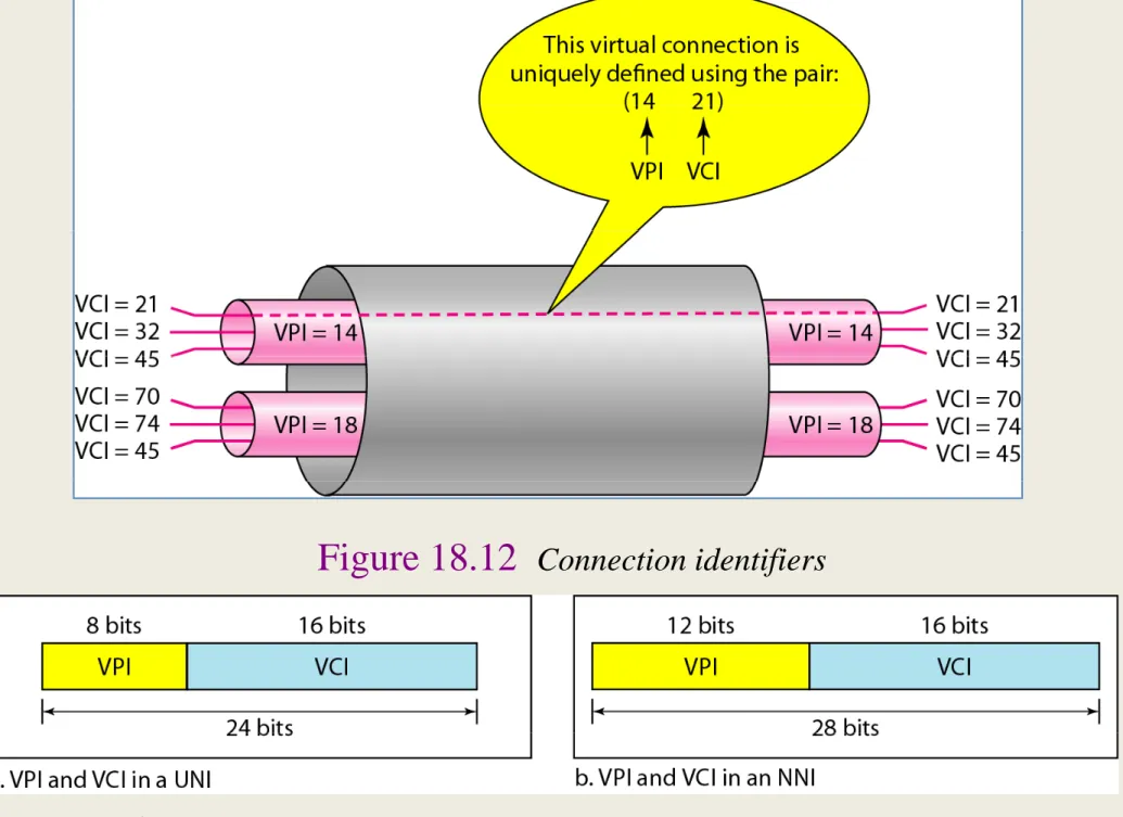
Identifiers
ATM Cells
ATM Services
ATM Services (Real‐Time Services)
ATM Services (NonReal‐Time Services)
An application using ABR specifies the maximum cell rate (PCR) it will use and the minimum cell rate (MCR) it requests. The main objective of GFR is to optimize the handling of frame-based traffic passing from the LAN through the router to the ATM backbone.
ATM vs Frame Relay
Frame relay uses variable length frames. y g
There is no flow control or error control