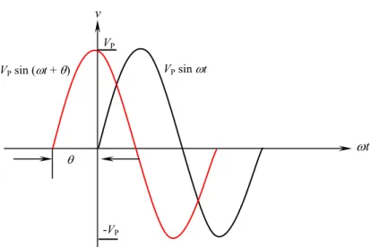
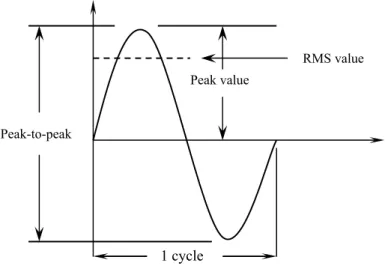
Where Vp is the maximum voltage, ω = 2πf is the angular velocity expressed in radians per second (rad/s), f is the frequency expressed in Hertz (Hz), t is the time expressed in seconds (s), and θ is the phase of the sinusoid expressed in degrees. Arc length is the distance along the arc of a circle from the origin to the end of the angle. The difference between the positive peak value and the negative peak value is called the peak-to-peak value of the sine wave.
This value is twice the maximum or peak value of the sine wave and is sometimes used to measure AC voltage. The value can be equal to zero if the specified moment is the time in the cycle during which the polarity of the voltage changes. The average value can be determined by summing a series of alternating current values (between 0° and 180°) and then dividing the sum by the number of current values used.
Also assume that the AC in Figure is increased until the temperature of the resistor is 100° C. However, the linear circuit does change the amplitude of the signal (amplification or attenuation) and shift its phase (causing the output signal to lead or lag the input).
Polar Form
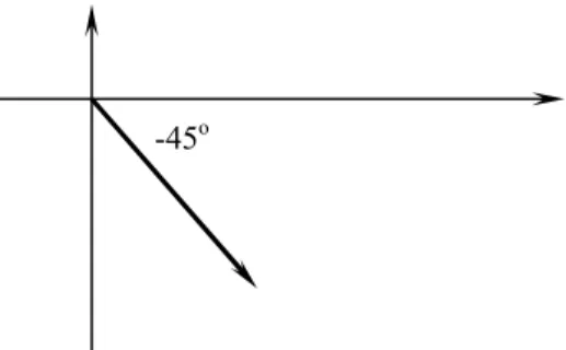
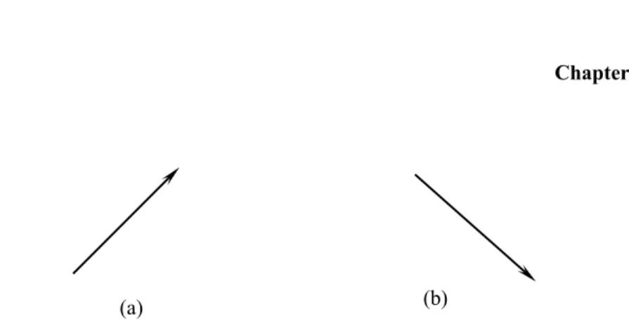
The polarity is very important: + means that the signal leads the reference; while – means that the signal lags behind the reference.
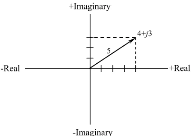
Rectangular Form
Transforming Forms
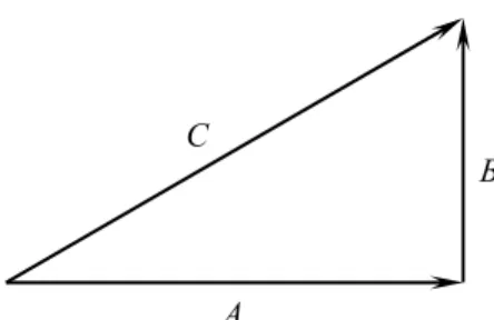
To convert from the polar to the rectangular form of a phasor, you need to convert C∠θ to A and B. From trigonometry, the cosine of an included angle relates to the length of the adjacent side and the length of the hypotenuse. In general, any load in rectangular form can be converted into polar form as follows.
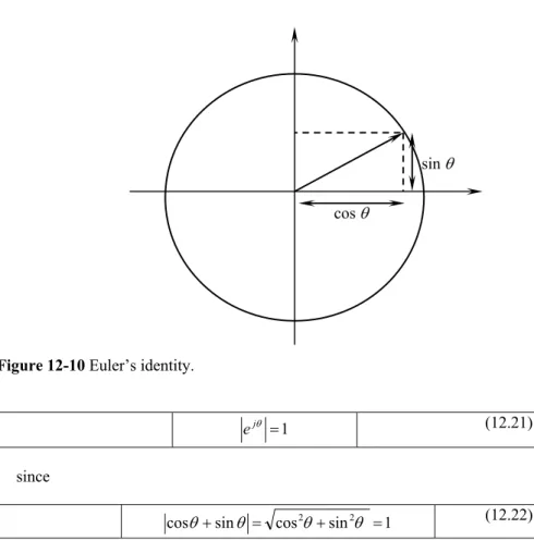
Euler’s Identity
Recall that writing Euler's identity is equivalent to equating the polar form of a complex number with its rectangular form. To multiply phasor quantities in rectangular form, multiply the numbers as if they were two binomials.
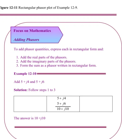
Simple Vector Addition
If two AC voltages, 90o out of phase, are added together by being connected in series, their voltage magnitudes do not add or subtract directly as with DC scalar voltages. Instead, these voltage quantities are complex quantities, and like the vectors above, add up in a trigonometric fashion. There is no suitable DC analogy for what we are seeing here with two AC voltages slightly out of phase.
With AC, two voltages can help or oppose each other to any degree between fully supportive and fully opposing, inclusive.
RESISTIVE LOADS
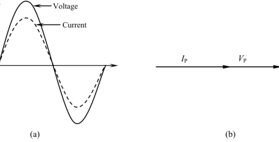
The voltage across the resistor is in phase with the current through the resistor since the phase angle is 0o. The 0o phase shift indicates that the voltage across the resistor is in phase with the current through it.
INDUCTIVE LOADS .1 Inductance
Inductive Reactance
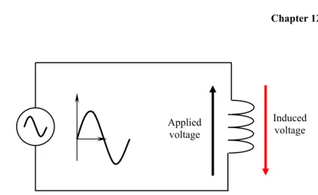
As the magnetic field changes magnitude and direction, a voltage is induced in the coil as shown in figure 12-17. The induced voltage can limit the flow of current through the circuit in a manner similar to resistance. Equation (12.32) states that the opposition an inductor presents to a sinusoidal current is proportional to the size of the inductor (L) and the value of the frequency.
Power in Inductive Load
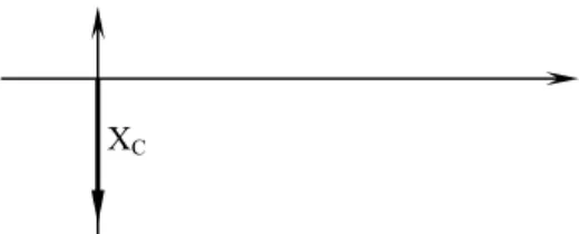
Therefore, the impedance of a capacitor is a frequency-dependent complex quantity, where the impedance of the capacitor varies as an inverse function of frequency. The capacitor acts as a short circuit at high frequencies, but behaves more like an open circuit at low frequencies. Equation (12.28) indicates that the resistance offered by a capacitor to a sinusoidal voltage is inversely proportional to the size of the capacitor (C) and the value of the frequency.
AC CIRCUIT ANALAYSIS
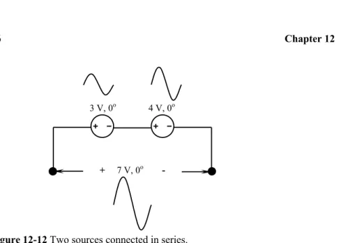
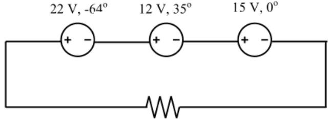
Consider three AC voltage sources in series (Figure 12-22) and use complex numbers to determine additive voltages. Graphically, the vectors add up in this way: The sum of these vectors will be a resultant vector that originates at the start point for the 22 V vector and ends at the end point for the 15 V vector. To determine the resultant vector's magnitude and angle without using graphics, we can convert and add each of these polar complex numbers into rectangular form.
What this means in real terms is that the measured voltage across these three voltage sources will be 36.80 V, which is 20.50o behind the 15 volts (0o phase reference). A voltmeter connected across these points in a real circuit will indicate only the polar magnitude of the voltage (36.80 V), not the angle. The same principle applies to AC ammeters: they indicate the polar magnitude of the current, not the phase angle.
Change the polarity of the three AC voltage sources from Example 12-25 (Figure 12-24) and use complex numbers to determine the additive voltages. Even though the angle is still written as 35o, the vector will be drawn 180o opposite as before: the resulting (sum) vector must start at the top left point (origin of the 22 volt vector) and end at the right arrowhead of the 15-V vector: The reversal of the connection on the 12-V supply can be represented in polar form in two different ways: by adding 180o to the vector angle (making it 12 V ∠215o), or by reversing sign of the magnitude (making it -12 V ∠35o).
POWER AND POWER FACTOR
Power Components
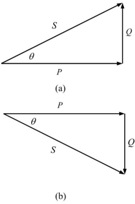
An example of reactive power used to provide a magnetic field is the magnetizing current consumed by a transformer or an electric motor. Whether a load consumes or supplies reactive power is a characteristic of the load itself. The relationship between these electrical power quantities is best realized using the power triangle shown in Figure 12-26 (a).
When an AC power is applied to a reactive load, the voltage is 90o out of phase with the current. When the instantaneous amplitudes of the voltage and current are multiplied, the resulting wave represents the instantaneous power of the reactor. Hence, the average power is zero, which means that reactive loads do not dissipate power.
Referring to Figure 12-26 (a), it can be seen that the base of the power triangle represents the real power component, while the vertical component represents the reactive power component. S = magnitude of power apparent in VA P = magnitude of real (active) power in W Q = magnitude of reactive power in VAR.
Power Factor
Because only the resistive part of an AC circuit dissipates power, we are interested in the resistive part of the impedance. The ratio of the circuit resistance to the amplitude of the circuit impedance is called power factor. In general, the power factor is related to the phase angle through the impedance diagram (Figure 12-26).
Leading and Lagging Power Factor
A leading power factor is one in which the current leads the applied voltage by a certain angle, as shown in Figure 12-27 (b).
THREE-PHASE AC CIRCUITS
Wye-Connected System
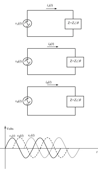
It is possible to connect the negative ends of these three single-phase generators and loads together so that they have a common neutral. In this case, four wires are required to feed three generators to a resistive load, as shown in Figure 12-29. The voltages between any two line terminals (a, b, or c) are called line-to-line voltages, and the voltages between any line terminal and the neutral terminal are called phase voltages.
Since the load connected to this generator is assumed to be resistive, the current in each phase of the generator will be at the same angle as the voltage. It is obvious that the current in any line is the same as the current in the corresponding phase.
Delta (∆) Connection
SUMMARY
PROBLEMS
12-12 Determine the power factor for each of the following circuit conditions and state whether it is leading or lagging. 12-13 Write the instantaneous equations for voltage and current for the phasor diagram shown in Figure 12-35 at a frequency of 800 Hz.