This is to certify that this project titled “IOT based Energy Meter and Bill Monitoring System” is being done by the following students under my direct supervision. This project work was carried out by them in the laboratories of the Department of Electrical and Electronic Engineering under the Faculty of Engineering, Sonargaon University (SU) in partial fulfillment of the requirements for the degree of Bachelor of Science in Electrical and Electronic Engineering. The report titled as on “IOT Based Energy Metering and Bill Monitoring System” has been prepared to fulfill the requirement of our practicum program.
First of all, we would like to thank the university authorities for allowing us to do the practicum. Coordinator, Department of Electrical and Electronics Engineering, SUSonargaon University, Dhaka, for his valuable and patient advice, kind help, cooperation and contribution of new idea. I would also like to thank Abul Bashar, the head of the department of SU, electrical engineering and electronics, professor dr.
LIST OF TABLE
INTRODUCTION
- Introduction
- Background
- Goal of the Work
- Problem Identification
- Project Objective
- Project Scope
Automation is a requirement in this era of information and communication technology where a smart control system is used to reduce or replace human operators in industry, offices or homes to produce certain goods or services. Load control and monitoring system is the subset of an automation system that allows us to intelligently control home appliances such as light, door, fan, air conditioner, etc. The load control and monitoring system can also ensure that home security and emergency systems are activated when needed.
This system is designed to be more user-friendly and easy to use at any level. The project is also designed to further vision work using minimal equipment at the lowest level of processing. The microcontroller is used as the heart of this Control and Monitoring System which controls all the operations involved.
THEORY OF THE PROJECT
Introduction
Hardware Used
Microcontroller
- ESP8266 Microcontroller
- ESP8266 Basic microcontroller
- Advantages of Microcontrollers
- Microcontrollers Applications
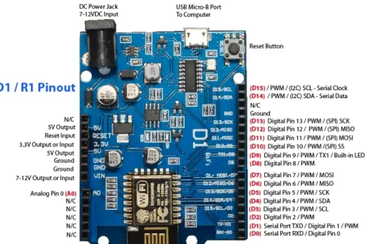
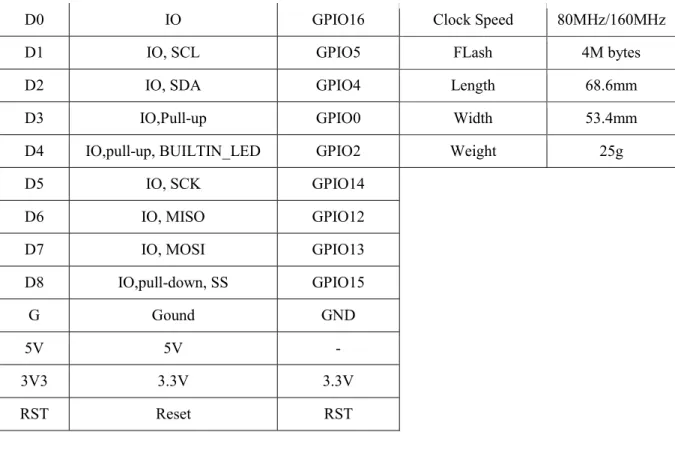
- WeMos D1 R1 Arduino Compatible ESP8266
- Technical Specs
- Resources
- WeMos D1 R1 Wi-Fi ESP8266 Board
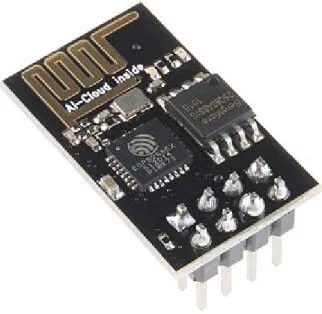
The ESP8266 is a low-cost Wi-Fi microchip with full TCP/IP stack and microcontroller capabilities manufactured by the manufacturer Express if Systems. This small module allows microcontrollers to connect to a Wi-Fi network and make simple TCP/IP connections using Hayes-style commands. However, at first there was almost no English-language documentation on the chip and the commands it accepted.
The ESP8285 is an ESP8266 with 1 MiB of built-in flash, allowing for Wi-Fi capable single-chip devices. The main advantages of microcontrollers are given. a) Microcontrollers act like a microcomputer without any digital parts. This WeMos development board is based on the ESP8266, which is a Wi-Fi communication IC built by Espressif.
At its core is a microcontroller that runs at a blazing 80 MHz and includes a built-in TCP/IP stack and transceiver that allows for Wi-Fi communications. This inexpensive option can not only add Wi-Fi capability to your next project, it can also run it. This board is a standalone microcontroller development board that can be easily programmed using the Arduino IDE.
Some of the peripherals provided by that ESP8266 include 9 GPIOs, 1 analog input, UART, SPI and TWI/I2C, and Wi-Fi. It operates at a logic level of 3.3 V and can be powered from the USB voltage or AC adapter input. The WeMos D1 uses the ESP 8266 microcontroller which is 2x faster than an Uno, has 160Kbs of RAM compared to an Uno's 2K and 100x the Flash memory.
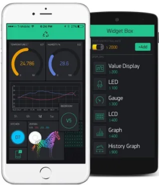
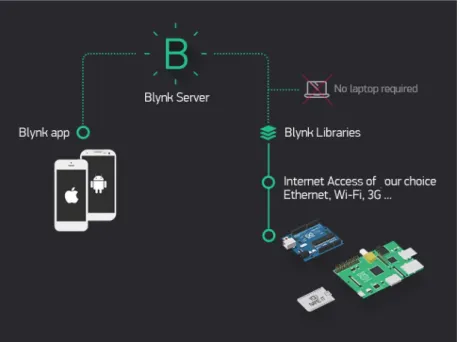
Blynk application Fundamentals
- Major features
Blynk app” It can remotely control hardware, it can display sensor data, it can store data, visualize it and do many other cool things. There are three main components in the platform: Blynk App - allows you to create amazing interfaces for our projects using various widgets.
Current Sensor
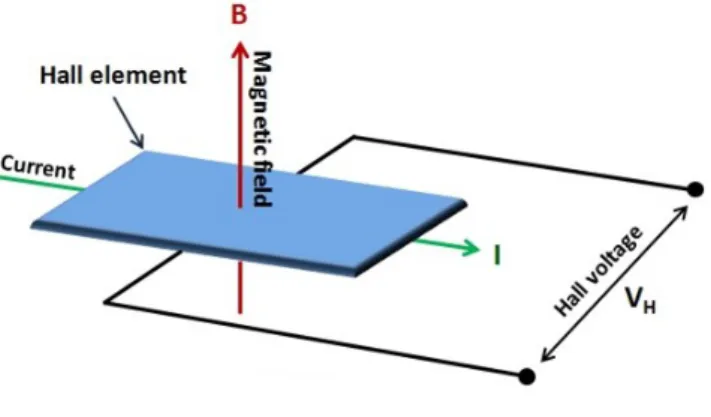
- Principle of Hall-effect
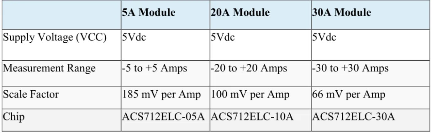
- Sensitivity and output of ACS712
- Sensor and Microcontroller connection
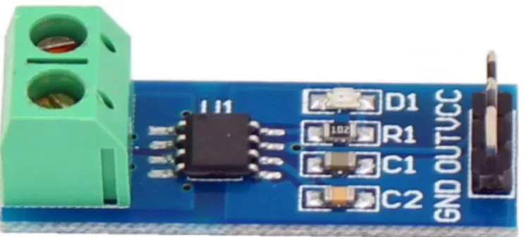
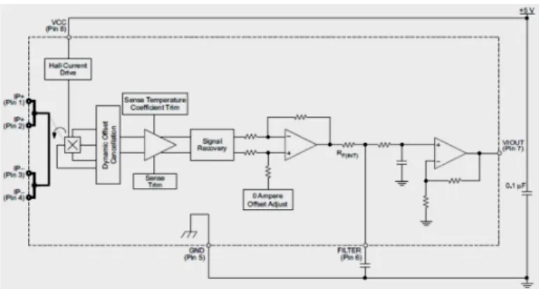
It consists of a precise, low-displacement, linear Hall sensor circuit with a copper conduction path located close to the die surface. The strength of the magnetic field is proportional to the magnitude of the current through the conduction path, providing a linear relationship between the output Hall voltage and the input conduction current. Since the terminals of this conduction path are electrically isolated from the sensor leads, the ACS712 device.
In low-frequency applications, it is often desirable to add a simple RC filter circuit at the output of the device to improve the signal-to-noise ratio. The ACS712 contains an internal resistor (RF) connected between the output of the on-chip signal amplifier and the input of the output buffer stage (shown below). It should be noted that the use of external capacitor increases the rise time of the sensor output and therefore sets the bandwidth of the input signal.
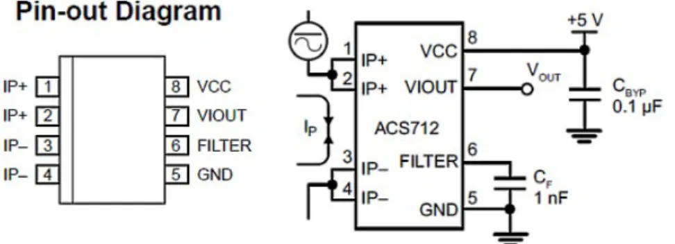
The output of the device is positive-sloping as increasing current flows through the copper conduction path (from pins 1 and 2 to pins 3 and 4). The ACS712-05B can measure current up to ±5A and provides an output sensitivity of 185mV/A (at +5V supply), which means that for every 1A increase in current through the conductive terminals in the positive direction, the output voltage also rises by 185mV. It should be noted that the ACS712 provides a metric output ratio, which means that the zero current output and sensitivity of the device is proportional to the supply voltage, VCC.
This feature is particularly useful when using the ACS712 with an analog-to-digital converter. The accuracy of any A/D conversion depends on the stability of the reference voltage used in the operation of the ADC. From this it can be seen that no fluctuation of the reference voltage will be a source of error in the analog-to-digital conversion of the ACS712 output signals.
The curve below shows the nominal sensitivity and transfer characteristics of the ACS712-05B sensor powered with a 5.0V supply.
Relay switch
- Principle
- Pin Description and Features
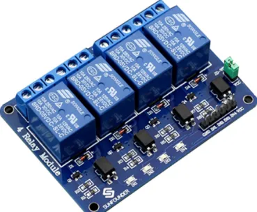
From the picture below, you can see that when the signal gate is low, the signal light will turn on and the 817c optocoupler (it transforms the electrical signals from the light and can isolate the input and output electrical signals) will conduct, and then the transistor will conduct, the relay coil will be electrified and the normally open relay contact will be closed. When the signal gate is high, the normally closed relay contact will close. So you can connect and disconnect the load by controlling the gate level of the control signal. The SRD-05VDC-SL-C relay has three high voltage terminals (NC, C and NO) which are connected to the device you want to control.
The other side has three low voltage pins (ground, Vcc and signal) which connect to Wemos D1 R1. When the relay receives a HIGH signal at the signal pin, the electromagnet is charged and moves the contacts of the switch to open or close. High quality Songle relay is used with single pole double throw, a common terminal, a normally open terminal and a normally closed terminal.
There are four fixed screw holes at each corner of the board, easy to install and adjust.
Transformer
Diode
Full wave rectifier
LCD Display
Buck Converter
Introduction
The integration of the modules is producing the system which can more or less be divided into two phases where the first phase is the output smart device system and the second phase is the input signal monitoring. The microcontroller, data signal converter, relay are in the first stage of the system and the device output is the second stage of the system.
System Overview
The full signal received by the WSN is then judged by the esp8266 and if there is a signal from the blynk application module then operate the relay to power the home appliance. There is a current sensor that monitors the current passing through it and sends the current reading to the microcontroller.
Operation using Arduino IDE
When the serial monitor shows "Ready to check RX & TX signal", the controller is ready to send and receive the data signal. Entering any data signal command, such as ON1, ON2, ON3, ON4, after sending this data serial monitor screen will activate or deactivate the corresponding relay.
Software Configuration
Circuit Diagram
RESULT AND DISCUSSION
- Introduction
- Output Results
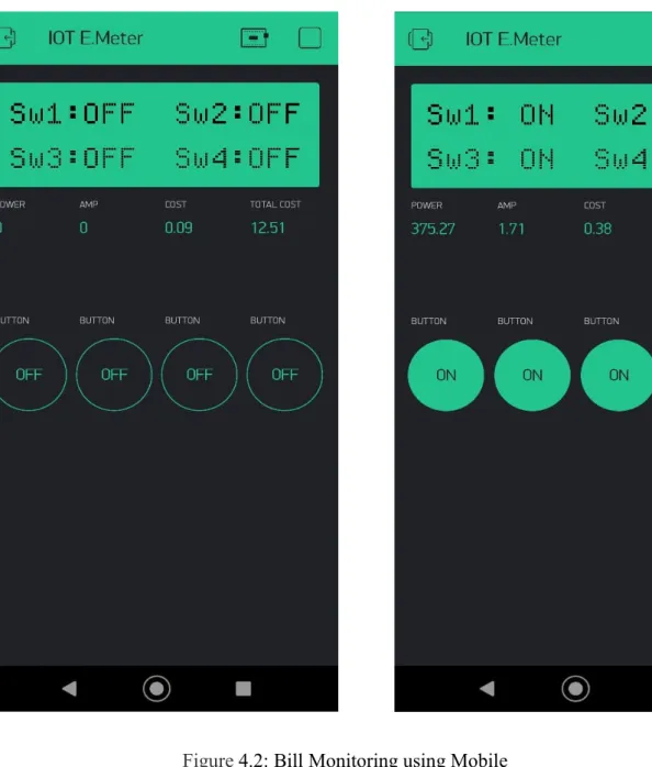
- Testing using Mobile Application
- Costing
- Discussion
The price of electronics is not stable for a developing country like Bangladesh, because Bangladesh never produces electronic parts, but imports from other developed countries, and during import, the price depends on the balance of foreign currency. Each time, a person is needed at the authority who will read the meters and issue a bill to the consumer. So, a smart energy meter provides automatic meter reading capabilities and can also detect meter failure by sending a message using IOT.
To indicate the output there are 4 lights so that we can see the output and make sure the module is working properly. Each WeMos D1 R1 pin needs to be programmed as needed, so it needs an Arduino IDE programming platform. The load control and monitoring system not only reduces the risk of electric shock, but also ensures human comfort, so it can also be used in industry to ensure human safety.
CONCLUSION
- Conclusion
- Application
- Advantage
- Limitation
- Future Recommendation
This load control and monitoring system can be improved by adding web server to store load and billing history which may require extra payment for domain server, voice control and camera system can also develop.
Determining the pedagogical conditions to form the readiness of future primary school teachers, Opción, Año 33. It is not necessary, but can positively affect the accuracy // Make sure that no current flows through the sensor at the moment. If you are not sure that the current through the sensor will not leak during calibration - comment on this method.