The report titled on improving the power factor of non-linear load using a boost converter with average current control. In electrical engineering, the power factor (PF) of an AC electrical system is defined as the ratio of the working power (measured in kilowatts, kW) absorbed by the load to the apparent power (measured in kilovolt-amps, kVA) flowing through the load. circuit.
Motivation
The continuous nature of the input current provides reduced levels of EMI without the use of additional filters. Some aspects on the design procedures of classical, interleaved and bridgeless boost converters are presented.
Aim and scope of the thesis
A uniform model g approximation for various control techniques based on the Fourier analysis of the input current is derived in [19], since it is possible to compare the transient response of three controllers. Moreover, the dynamic behavior of the converter when subjected to load steps is experimentally analyzed.
Advantages of high transmission voltage
Power Factor Improvement
Resistive loads in an electrical circuit have a power factor of unity, while for a purely inductive load the power factor is zero. This combination of inductive and resistive loads makes the power factor of the plant one value.
Working Principle
The lower the power factor, the greater the losses, or in other words, for the device to work efficiently, the power factor must be close to unity. The required capacitance value is a function of the type of electrical load in the device.
Installation Guidelines
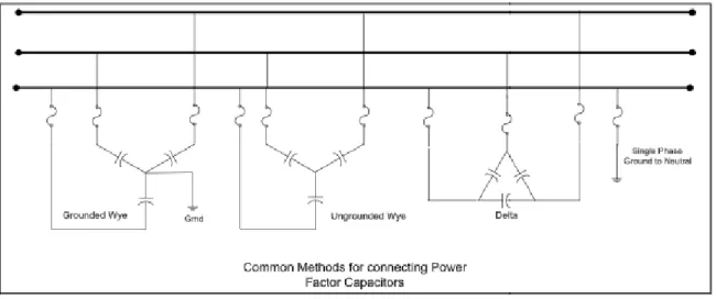
Grounded wye connections ensure faster operation of series fuses in case of capacitor failure. Grounded capacitors can bypass a line-to-ground surge and therefore exhibit a certain degree of self-protection against transient voltages and lightning surges.
Estimation of KVAR required to improve power factor
KVAR) required to improve the power factor of a load P (KW)
Case Study
Static Capacitor
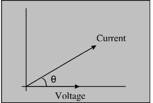
To improve the power factor, static capacitors are connected in parallel with devices operating at low power factors. Suppose there is a single load consuming a lagging current (I), and the power factor of the load is Cosθ, as shown in Figure 1. Note also that after the power factor improvement, the circuit current would be lower than at a circuit current with a low power factor.
Also, before and after the power factor improvement, the active component of current would be the same in that circuit because the capacitor only eliminates the reactive component of current. Also, the active power (in watts) would be the same after and before power factor improvement.
Advantages
Disadvantages
Synchronous Condenser
Phase Advancer
The phase amplifier can easily be used where the use of synchronous motors is unacceptable.
Disadvantage
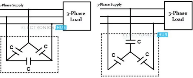
Power Factor Improvement in single-phase and three-phase star & delta connections
Good to know
Passive filters connected between the non-linear load and the series active power filter play an important role in compensating the harmonics of the load current. By connecting passive filters in series, the active power filter acts as a harmonic isolator. The passive filter can be tuned to the dominant harmonics of the load and can be designed to correct the power factor of the load displacement.
However, for industrial loads connected to the rigid supply, it is difficult to design passive filters that can absorb a significant portion of the load's harmonic current, and therefore their effectiveness deteriorates. For these types of applications, the passive filter cannot be precisely matched to the harmonic frequencies because they can become overloaded due to system voltage distortion and/or system current harmonics.
Principles of Operation
- Boost Converter with Average Current Control
- Power Factor with Different Loads
- Types of Power Factor Correction 1. Passive PFC
- Active PFC
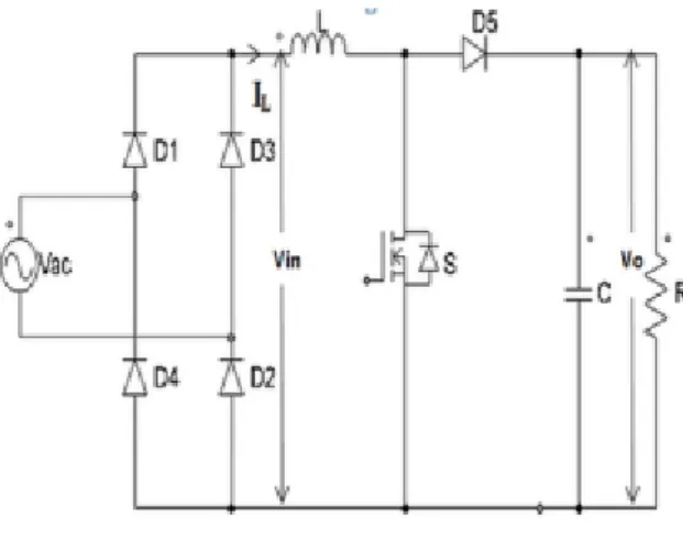
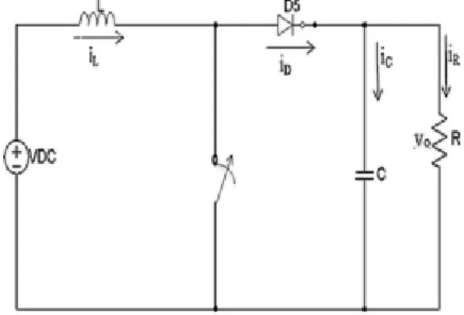
- Boost Converter
- Average Current Mode Control System specifications
- Summary
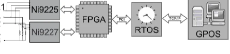
- THE SOFTWARE OF THE SYSTEM
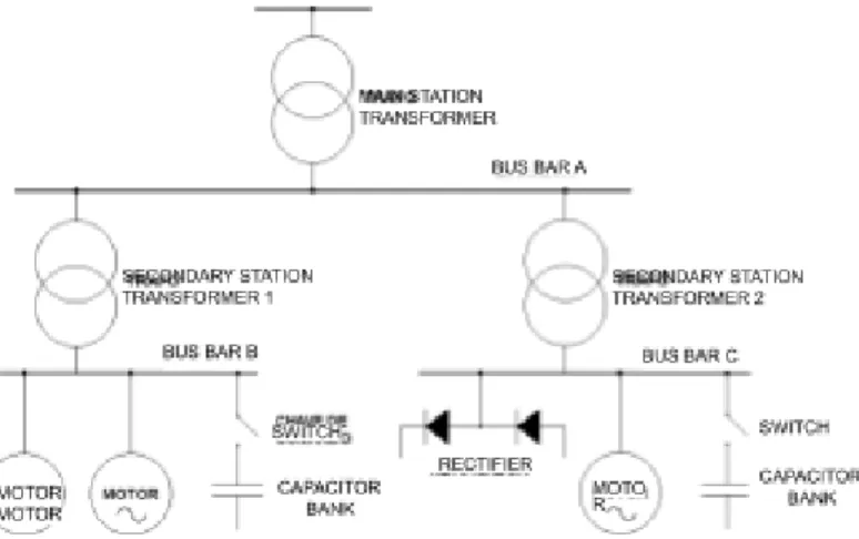
- CHARACTERIZATION OF NONLINEAR LOADS IN POWER DISTRIBUTION GRID
- PARAMETER DEFINTIONS
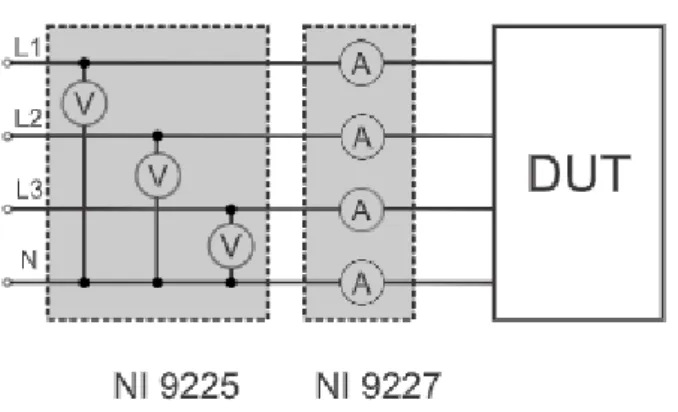
- MEASUREMENT SYSTEM
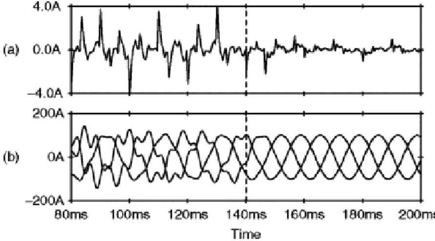
- MEASUREMENT RESULTS
- SUMMARY
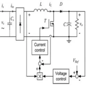
Power factor is defined as the cosine of the angle between voltage and current in an AC circuit. The gain modulator multiplies or is the product of the reference current and the error voltage from the error amplifier (defined by the output voltage). The average current control method resulted in improved performance and improved results (THD and PF).
In the results of the uncontrolled rectifiers, it can be seen that the harmonics are very high. At the same time, household consumption is expected to reach 40% of the total demand for electricity. We will then demonstrate our new results by implementing the theory and measurement tools on a set of nonlinear loads.
Similar conclusion can be made by comparing the Distortion (D) and the power of the first (fundamental) harmonic (P 1).
Chapter-4
General Perspective
Peak Current Mode Control Problems Poor noise immunity
APPLICATION NOTE-01
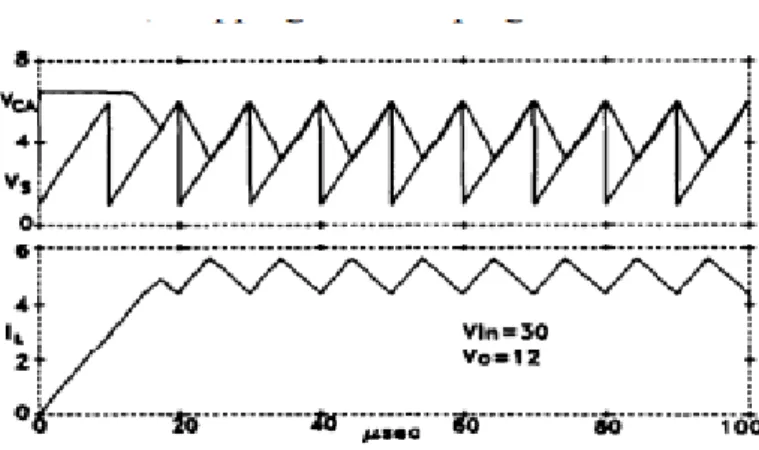
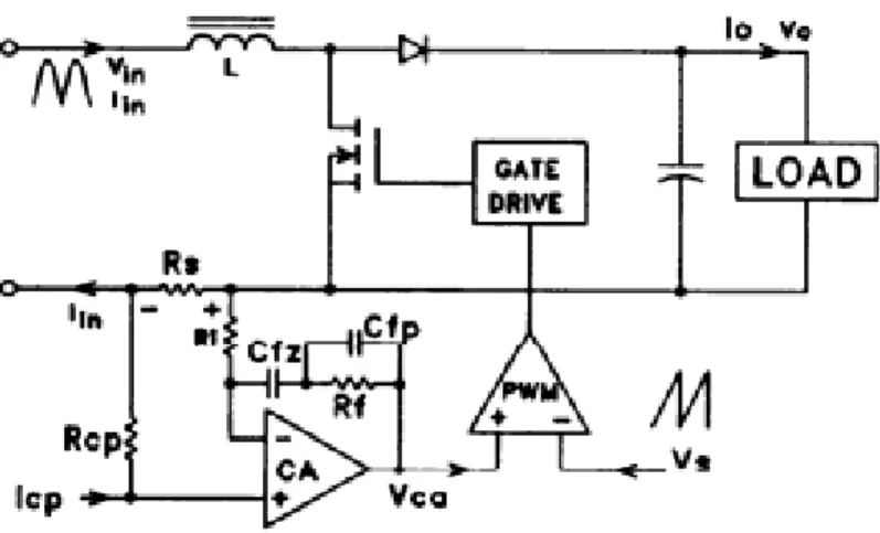
The amplified inductor current slope at one input of the PWM comparator must not exceed the oscillator ramp slope at the other input of the comparator. To avoid subharmonic oscillations, this out-of-time CA output slope must not exceed the oscillator ramp slope. The CA output slope is much less than the oscillator ramp slope, indicating that the CA gain is less than optimal.
Slope Calculation: Inductor Current Slope = Oscillator Ramp Slope Vo/L = Vs/Ts = Vsfs Where Vs is the p-p voltage of the oscillator ramp, Ts and fs are the period and switching frequency. Where Vs is the p-p voltage of the oscillator ramp, Ts and fs are the switching period and frequency.
APPLICATION NOTE-02
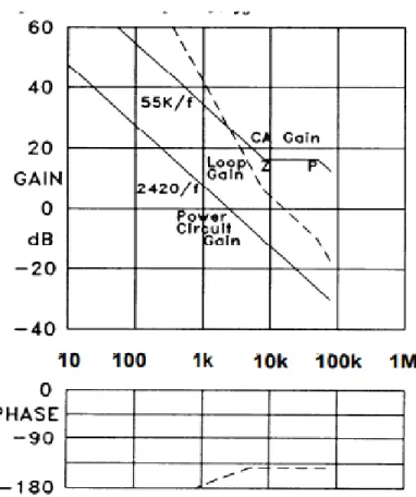
If you set the CA gain to the limit in (1), the crossover frequency will never be lower than one-sixth the switching frequency. Although the comparator actually turns off the on switch when the peak inductor current is reached, this peak current level is adjusted by the current amplifier so that the average current is correct. Note how the amplified and reversed downward coil current practically coincides with the oscillator ramp because the CA gain has been set to the optimum level according to equation (1).
Note also that if the CA gain is increased further, not only will the off-time slope exceed the oscillator slope, but the positive swing may reach the CA compliance limit, clipping or clamping the waveform. The reduced amplitude and slopes of the CA waveform due to the 100 kHz pole may indicate that the CA gain may be in.
APPLICATION NOTE-03
In the discontinuous mode, below the mode boundary, changes in Io require large duty cycle changes. Furthermore, the single-pole characteristic of continuous operation with its 90° phase lag disappears so that the gain of the current circuit is flat independent of frequency. With peak current mode control in the discontinuous mode, the peak/average current error becomes unacceptably large.
But in average current mode control, the high gain of the current error amplifier readily accommodates the large duty cycle changes necessary to accommodate changes in load current, thus maintaining good average current control. 2, when the current loop is closed, the voltage across the current sense resistor VRS& is equal to the current programming voltage VCP& (from the voltage error amplifier) at frequencies below fs.
APPLICATION NOTE-04
The closed-loop transconductance rolls off and assumes a single-pole characteristic at the open-loop transition frequency fs. Using the values for this application, the maximum GCA is 6.58, which is achieved by making RF/RI = 6.58. Note that (7) is almost identical to (2) for the buck regulator, except that the gain depends on Vo. which is constant), instead of VIN.
As with the previous example, with a flat gain error amplifier the phase margin at crossover is 90°.
APPLICATION NOTE-05
In a preregular high power factor application, the current is programmed to follow the rectified line voltage. As the rectified sine wave voltage and current approach, peaking at zero, the inductor current becomes discontinuous. Discontinuous operation can occur over a significant portion of the line cycle, especially when the line current is low at high line voltage and/or low power input.
The upper waveforms show the duty cycles of the switch and diode throughout the line cycle. The inductor current is continuous when the current is high, and the switch and diode duty cycles add up to 1.
APPLICATION NOTE- 06
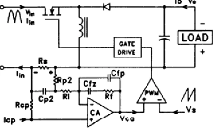
But if it is desired to use a buck or flyback topology to control input current in a high power factor application, then the chopped current waveform must be averaged through the power switch, a more difficult task. The flyback converter can be designed to operate in the discontinuous inductor current mode in this application. The discontinuous flyback converter is not difficult to (crudely) control by fixing the duty cycle during each line half cycle, but the peak currents through the power switch and rectifier are almost twice as high as with continuous mode operation.
In this example, the fly back converter operates in continuous mode when it is important to do so at high current levels, to keep the maximum peak current at half that of a strictly discontinuous fly back converter. Unlike the boost converter, the flyback input current is clipped so that the maximum 100kHz current passes through.
APPLICATION NOTE- 07
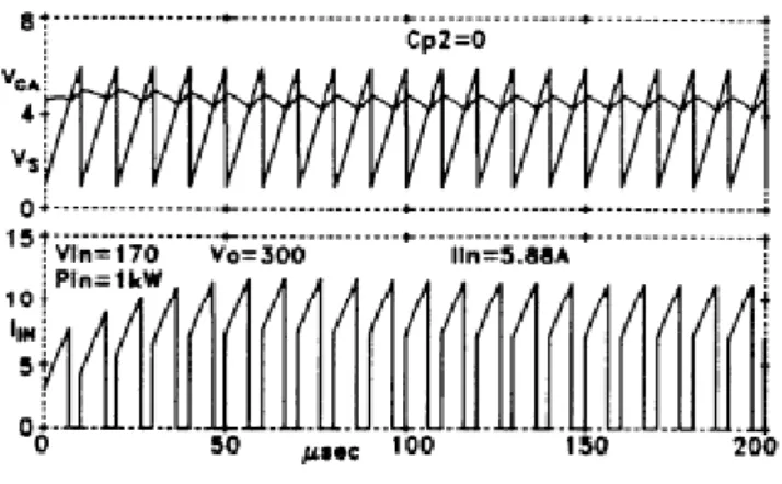
Turning now to the current error amplifier (Fig. 11), the input current (switch) clipped waveform is shown in Fig. The CA gain in the vicinity of 100 kHz is determined by the (RI,+RP2)CFP integrator. This is the same principle used in the previous two examples, but in those cases the inductor (whose current was being controlled) did most of the work.
The inductor provided the integration to provide the triangular ripple current waveform and the CA gain was close to this. The upslope of the CA output occurs when the switch is off and the 100 kHz current waveform is zero.
SUMMARY
Model design & Simulation
- Model Design
- PI controller
- Output current & Output voltage (Without power factor improvement)
- Input Current & Input Voltage with power factor improvement
- Output Current with power factor improvement
- SUMMARY
- Table of comparison
- Conclusion
- References
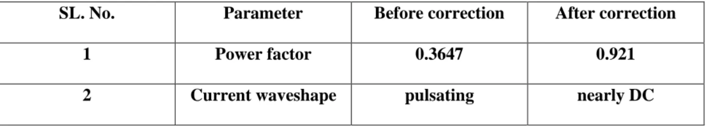
Here we show that input and output voltage waveform without power factor improvement in this graph we calculated that the waveform is distorted becomes of harmonics. In this circuit, the output current and output voltage are before adding the power factor improvement method. These two figure that the waveform pulsates about nature. After adding the power factor improvement method, the input current and input voltage are almost pure sinusoidal, calculated to reduce the harmonic arc.
The power factor of the source with the rectifier as a non-linear load is also very poor, the THD is quite high. After adding a boost converter with a control mechanism, the power factor is improved to the desired level and the THD is also reduced.