Power Generation Using Micro Hydro Turbine
A report submitted to the Department of Mechanical, Sonargaon University of Bangladesh in partial fulfillment of the requirements for the Award of Degree of
Bachelor of Science in Mechanical Engineering.
Submitted by
Md. Sona Mia ID: BME 1902018323 Md. Ashik Ali ID: BME 1902018218 Md. Al-Amin ID: BME 1902018233 Md. Zakir Hossain ID: BME 1902018301 Md. Kawser Howlader ID: BME 1703013254 Most. Rubina Akter ID: BME 1902018031
Supervised by Md. Shadrul Alam Assistant Professor
Department of Mechanical Engineering Sonargaon University (SU)
Dhaka-1215, Bangladesh
DECLARATION OF AUTHORSHIP
We do hereby solemnly declare that, the work presented here in this project report has been carried out by us and has not been previously submitted to any University/
Organization for award of any degree or certificate
We hereby ensure that the works that has been prevented here does not breach any existing copyright.
We further undertake to indemnify the university against any loss or damage arising from breach of the foregoing obligation.
Submitted By- Supervised By-
Md. Sona Mia Md. Shadrul Alam
BME 1902018323 Assistant Professor
Department of ME
Md. Ashik Ali Sonargaon University
BME 1902018218
Md. Al-Amin BME 1902018233
Md. Zakir Hossain BME 1902018301
Md. Kawser Howlader BME 1703013254 Most. Rubina Akter BME 1902018031
ACKNOWLEDGEMENT
First, we started in the name of almighty Allah. This thesis is accomplished under the supervision of Md. Shadrul Alam, Assistant Professor, Department of Mechanical, Sonargaon University. It is a great pleasure to acknowledge our profound gratitude and respect to our supervisor for this consistent guidance, encouragement, helpful suggestion, constructive criticism and endless patience through the progress of this work. The successful completion of this thesis would not have been possible without his persistent motivation and continuous guidance.
The authors are also grateful to Md. Mostofa Hossain, Head of the Department of Mechanical Engineering and all respect teachers of the Mechanical Engineering Department for their co-operation and significant help for completing the thesis work successfully.
[Authors]
Md. Sona Mia BME 1902018323
Md. Al-Amin BME 1902018233
Md. Ashik Ali BME 1902018218
Md. Zakir Hossain BME 1902018301
Md. Kawser Howlader BME 1703013254
Most. Rubina Akter BME 1902018031
ABSTARCT
Flowing water creates energy that can be captured and turned into electricity. This is called hydroelectric power or hydro-power. Hydro-power is considered a renewable energy resource because it uses the earth's water cycle to generate electricity. Water evaporates from the earth's surface, forms clouds, precipitates back to earth, and flows toward the ocean. As far as Bangladesh is concerned, only a small fraction of electricity is generated by hydro-power. The government has set a target of meeting five per cent of the electricity demand by 2015 by utilizing renewable energy, and 10 per cent by the year 2020.
Currently, renewable energies contribute to less than one per cent of the country's total electricity generation .The aim of our thesis is was to demonstrate and observe the demo hydro-power in micro-scale by our experimental setup which is completely new in concept .This thesis paper consists results of our findings and might help in case of utilizing this renewable energy potential.
TABLE OF CONTENTS
Declaration of Authorship i
Acknowledgement ii
Abstract iii
Table of Contents iv
Table of Figures vi
List of Tables vii
CHAPTER-1 INTRODUCTION
1.1 Introduction 1
1.2 Energy Scenario in BD 2
1.3 Objective 3
CHAPTER 2 LITERATURE REVIEW
2.1 Introduction 4
2.2 Hydro-electric Power 4
2.3 Hydro Site in BD 4
2.4 Literature Review 5
2.5 Summary 6
CHAPTER-3 HARDWARE AND SOFTWARE ANALYSIS
3.1 Required Instruments 7
3.2 Turbine 8
3.3 Mini Generator Motor 9
3.4 12V Battery 10
3.5 Inverter Circuit 11
3.5.1 CD 4047 12
3.5.2 MOSFET 14
3.6 Transformer 16
3.7 High Speed Pump 19
3.8 Digital Volt Ammeter 20
3.9 Smoothing Capacitor 21
3.10 Resistor 23
3.11 Proteus Software 24
CHAPTER-4 METHODOLOGY
4.1 Methodology 25
4.2 Block Diagram 25
4.3 Schematic Diagram 26
4.4 Working Principle 26
4.5 Our Final Project View 27
CHAPTER-5 RESULT AND DISCUSSION
5.1 Result 28
5.2 Discussion 29
CHAPTER-6 APPLICATION AND COST ANALYSIS
6.1 Project Cost Analysis 30
6.2 Advantages 31
6.3 Applications 31
6.4 Limitation 32
CHAPTER-7 CONCLUSION
7.1 Conclusion 33
7.2 Future Scope 33
Reference 34
LIST OF FIGURES
FIGURE NO FIGURE NAME PAGE NO
1.1 Operation of water Wheel 7
3.1 Turbine 8
3.2 Mini Gear Motor 9
3.3 Battery 10
3.4 Inverter Circuit 11
3.5 IC CD4047 12
3.6 Simple Inverter Circuit Using CD4047 13
3.7 MOSFET 14
3.8 MOSFET Diagram 15
3.9 Step UP Transformer 17
3.10 Full Wave Bridge Rectifier 17
3.11 Positive Half Cycle of Full Wave Bridge Rectifier 18 3.12 Negative Half Cycle of Full Wave Bridge Rectifier 18
3.13 High Speed Pump 19
3.14 Voltmeter Ammeter Dual Display 20
3.15 Capacitor 21
3.16 The Smoothing Capacitor 22
3.17 Two Common Resistor 23
3.18 Proteus Software Interface 24
4.1 Block Diagram 25
4.2 Schematic Diagram 26
4.3 Our Final System Overview 27
5.1 Efficiency Curve (Efficiency Vs Load) 28
5.2 Efficiency vs Flow Rate Carve 29
LIST OF TABLES
TABLE NO TABLE NAME PAGE NO
01 Project Cost Analysis 30
CHAPTER 1
INTRODUCTION
1.1 Introduction
Turbine is any of various devices that convert the energy in a stream of fluid into mechanical energy. The conversion is generally accomplished by passing the fluid through a system of stationary passages or vanes that alternate with passages consisting of fin like blades attached to a rotor. By arranging the flow so that a tangential force, or torque, is exerted on the rotor blades, the rotor turns, and work is extracted [1]. Turbines can be classified into four general types according to the fluids used as water, steam, gas, and wind. Although the same principles apply to all turbines, their specific designs differ sufficiently to merit separate descriptions [2]. Water turbine is a rotary machine that converts kinetic energy and potential energy of water into mechanical work. Water turbines may be defined as prime movers that transform the kinetic energy of the falling water into mechanical energy of rotation and whose primary function is to drive an electric generator.
One cubic meter of water can give about 9800 Joules of mechanical energy for every meter it descends and a flow of a cubic meter per second in a fall of 1 meter can provide 9800 W of power [3] studied on hydroelectric power plant design and a computer program was developed named Hydro Electric Plant Specification. This computer software was used for the rapid determination of plant specifications for different dams. [4] reported that household in this contemporary time uses electricity for domestic comfort. The researcher stated that most functions of our society were based on the use of energy. It was concluded that elaborate networks of energy supply had been developed in the last three centuries in which electricity was fed into communities by the transmission lines of the electric grid at high voltage.
According to the [5] stated that water cycle occurred naturally and this resulted to rainfall which transferred millions of tons of water annually to high elevations with significant potential energy. The river that flows on the planet carry the very high amounts of potential and kinetic energy, which currently turn the turbines of several hydroelectric
demand of the planet.[6] The commonly used turbine is Pelton wheel type, this turbine uses spoon shaped buckets to harness the energy of failing water. It consists of a rotor equipped with buckets along the whole periphery of the turbine. The buckets are of elliptical shape. The quantity of water discharged by the nozzle can be controlled by controlling the nozzle’s opening by means of needle placed in the tip of the nozzle [7].
A water turbine uses the potential energy resulting from the difference in elevation between an upstream water reservoir and the turbine exit water level (the tailrace) to convert this so-called head into work. Today, the primary use of water turbines is for electric power generation. Now they are mostly used for electric power generation. Water turbines are mostly found in dams to generate electric power from water potential energy [8]. The earliest known water turbines date to the Roman Empire. The horizontal water wheel with angled blades was installed at the bottom of a water-filled, circular shaft. The water from the mill-race entered the pit tangentially, creating a swirling water column which made the fully submerged wheel act like a true turbine [9]. The water wheel operation from converting the potential to kinetic energy as shown in Fig. 1.
Figure 1.1: Operation of a water wheel [1]
1.2 Energy Scenario In Bangladesh
The main sources of power generation are hydro-power, bio fuels, coal, and natural gas.
Large-scale hydro-power (>40 MW) generation has been established which leads to resettlements thus losing agricultural lands. The nation has a high dependency on natural gas and hydro-power for electricity generation but, as mentioned previously, low per
capita energy consumption. The reserve for these fossil fuels is depleting at a high rate. At present the country does not have any energy security, and this is why after the fossil fuels are completely consumed, the country will face severe energy crisis. That is a huge concern for the mass people of the country. On the other hand, the country is seriously affected by the natural calamities. Thus, energy sustainability is another important aspect that should be taken into consideration. All these factors lead to the inability to consider energy sustainability. Generating more power from fossil fuels to overcome the gap between demand and supply has made it even more difficult to attain energy sustainability due to their high depletion rate. As a result, the circumstances are such that alternative energy sources other than fossil fuels should be taken into consideration to have a secured and sustainable energy future.
The current reserves for fossil fuels in Bangladesh should be analyzed. Bangladesh has modest hydrocarbon resources and rich renewable energy sources especially in the form of traditional energy. The Natural gas reserves in Bangladesh are likely to be depleted before 2020 which will bring the power generation at a halt. In Barapukuria, the deposits of Coal may supply about 250 MW [8]. When the demands for electricity would exceed 11000 MW, emergency measures should be taken to conserve energy, to achieve high-efficiency plants, explore gas, and coal reserves to prevent the inevitable disaster due to the lack of power supply. The Government of Bangladesh is planning to tackle the situation by renting power systems and coal-fired systems. But more importantly energy supplies using RETs must be developed and utilized.
1.3 Objectives
We have some specific objectives for this project and they are pointed below:
To Design & Construct of aPower Generation Using Hydro Turbine.
To Implement of generate electrical power with the help of hydro turbine.
To Generate electric power, store it in battery and use use in AC load.
To study the system performance for future reference and improvement purposes.
CHAPTER 2
LITERATURE REVIEW
2.1 Introduction
In this section topics related to Power Generation Using Hydro Turbine System are included. These provide a sampling of problems appropriate for application of Power Generation Using Hydro TurbineSystem. The references are summarized below.
2.2 Hydro-electric Power
Photo of water spilling at dam hydroelectric power, or hydroelectricity, is generated by the force of falling water. (Hydro comes from the Greek word for water.) It’s one of the cleanest sources of energy, and it’s also the most reliable and costs the least. That means that TVA’s hydroelectric power plants are able provide electricity at a reasonable cost to families, schools, farms, factories, and businesses.
2.3 Hydro sites in Bangladesh
In February 1981, the Water Development Board and Power Development jointly carried out a study on the assessment of Small/Mini-Hydro-power Potential in the country. The committee explored 19 prospective sites for possible installation of small hydro-power plants. Later in the month of April 1984, Six Chinese experts visited Bangladesh and they identified 12 potential sites for development of mini hydro-power plant. Out of these sites, only Mahamaya Chara, near Mirersharai, close to Dhaka-Chittagong highway was identified as the best site for development of small hydro. Following are the sites that were identified.
In 2004 sustainable Rural Energy, Local government Engineering Department has explored some potential micro hydro sites in Chittagong which is listed in Most of the potential sites are situated in the Chittagong hill tracts (CHTs). It requires potential utilization of hydro-power and indigenous technical knowledge to utilize the existing opportunities in the CHT areas. Decentralization of micro-hydro-power units with local
implementation and management through self-reliance and the use of local natural resources will have significant impact on the remote tribal rural development.
Mr. Aung Thui Khoin set such an instance by setting up a micro-hydro-plant. The unit was constructed with wooden turbine and making an earthen dam on the flowing Hara Khal at remote hilly region of Monjaipara, Bandarban. About 10 kW electricity is being generated by this micro hydro-power unit that has illuminated 40 households of that village. That led to an agreement between LGED and innovator Mr. Aung Thui Khoin for a month long study. The objectives of the study were identification of micro hydro-power potential sites within the hilly regions and promotion of indigenous technologies for development of hydro-power. Possible integration with power generation and irrigation schemes was also under consideration. From the study, some prospective sites for micro-hydro-power development in three districts of CHT region were identified with the help of LGED officials, local communities, and head man. Various data are collected through the related instruments regarding the Micro-Mini-Hydro study at two selected places of (1) Shailopropat, Bandarban, and (2) Madhobkundu, Moulibhibazar.
2.4 Literature Review
Deshmukh and Bilolikar [1] studied the feasibility of grid extension and distributed generation considerating biomass and diesel based generation options and BEP (break even point) based optimization suggested it as a cheaper option than grid extension.
Monteiro [2]have studied the impact of integration of distributed resources on electricity distribution using a spatial support system. Geographical information systems (GIS) was used by Zhou Quan [3] to develop mathematical models of the substation location and capacity optimization and proposed a new multi period optimal selection algorithm of substation that can determine the reasonable location, capacity and time of substation operation.
Khator and Leung [4]reviewed the models related to the planning of substations and/or distribution feeders under two major groups: planning under normal conditions and planning for emergency and found the power distribution planning as difficult to ensure substation capacity (transformer capacity) and feeder capacity (distribution capacity) to
meet the load demands. A new methodology was developed by Monteiro [5] for automated route selection for the construction of new power lines based on GIS considering the environmental constraint, operation and maintenance and equipment installation costs associated with the slope of the terrain crossed by the power lines.
Jewell, Grossardt and Bailey [6]developed a new method to reduce public opposition to new lines by way of public participation in transmission line routing decisions and hence the time needed for the approval of new line construction. A fast algorithm was presented by Tram and Wall [7] to help select the proper conductors for feeder expansion plans including selection of optimal conductor type for each feeder segment to maintain an acceptable voltage profile along the entire feeder and minimize the capital investment and the cost of feeder losses.Urban, Bandars and Moll [8] developed six different scenarios of rural electrification for the period 2005-2030 using a regional energy model (REM) to assess the effect of green house gases (GHGs), primary energy use and the costs and compared the business-as-usual (BAU) scenario with different rural electrification scenario based on electricity from renewable, diesel and the grid. The results indicated that rural electrification with renewable energy tends to be the most cost effective option.
Kaundinya, Balachandra and Ravindranath [9]have studied the modeling and analysis of economic, environmental technical feasibilities of both grid connected and standalone system as decentralized power options, which was restricted to annualized life cycle cost (ALCC) methods.
2.5 Summary
Hydro is a major primary source of energy in Bangladesh especially in the north-eastern hilly regions. Promoting renewable energy sources for energy requirements in conjunction with alleviation of rural poverty, diversification of energy resources and reduction of oil imports are needed to shift the economic growth towards greater sustainability, as well as environmental and social stability. We try to do this project by reading the above literature, and we have been able to make our project successful by reducing the mistakes of last year's project.
CHAPTER 3
HARDWARE AND SOFTWARE ANALYSIS
3.1 Required Instrument’s
Hardware consists of interconnected electronic components which perform analog or logic operations on received and locally stored information to produce as output or store resulting new information. Here we user various hardware in this project. Details description is given below.
Hardware:
1) Turbine 2) Motor 3) Battery
4) Inverter Circuit 5) CD 4047 IC 6) MOSFET 7) Transformer 8) High Speed Pump 9) Volt Ammeter Meter 10) Smoothing Capacitor 11) Resistor
Software:
1)Proteus
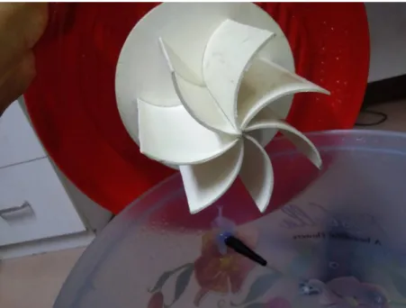
3.2 Turbine
A turbine is a rotary mechanical device that extracts energy from a fluid flow and converts it into useful work. The work produced by a turbine can be used for generating electrical power when combined with a generator. A turbine is a turbomachine with at least one moving part called a rotor assembly, which is a shaft or drum with blades attached.
Moving fluid acts on the blades so that they move and impart rotational energy to the rotor.
Early turbine examples are windmills and waterwheels. Gas, steam, and water turbines have a casing around the blades that contains and controls the working fluid.
Figure 3.1: Turbine
Operation Theory
A working fluid contains potential energy (pressure head) and kinetic energy (velocity head). The fluid may be compressible or incompressible. Several physical principles are employed by turbines to collect this energy. Impulse turbines change the direction of flow of a high velocity fluid or gas jet. The resulting impulse spins the turbine and leaves the fluid flow with diminished kinetic energy. There is no pressure change of the fluid or gas in the turbine blades (the moving blades), as in the case of a steam or gas turbine, all the pressure drop takes place in the stationary blades. Before reaching the turbine, the fluid's pressure head is changed to velocity head by accelerating the fluid with a nozzle. Pelton wheels and de Laval turbines use this process exclusively. Impulse
turbines do not require a pressure casement around the rotor since the fluid jet is created by the nozzle prior to reaching the blades on the rotor. Newton's second law describes the transfer of energy for impulse turbines.
3.3 Mini Generator Motor
Specification
Output: 12Volts DC, 100 RPM
Voltage Output: 0-50V DC
Maximum Generator Output: 15 Watts Feature
Optimized for wind turbine speeds
1/8” Shaft Diameter
The shaft a flat spot for attaching the blade
Generate 12 volts at 1000 rrpm
Two 3.16 spade terminals for power connection
Include separate blocking diode
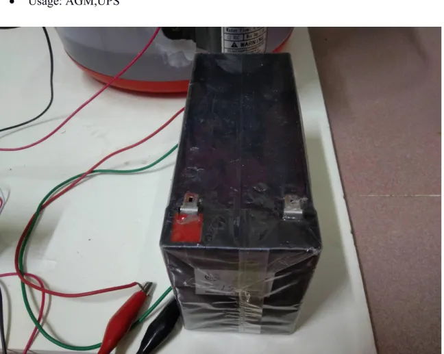
3.4 Battery
A twelve-volt battery has six single cells in series producing a fully charged output voltage of 12.6 volts. A battery cell consists of two lead plates a positive plate covered with a paste of lead dioxide and a negative made of sponge lead, with an insulating material (separator) in between.
Quick Details
Rechargeable 12v dc battery pack: 1PCS/CTN(according to the actual situation)
Production Capacity: rechargeable 12v dc battery pack:50000PCS/Month
Battery Production Lines: 5
Factory space: 6000m2
Voltage: 12V
Size: 522*240*220/225mm
Usage: AGM,UPS
Figure 3.3: 12V Battery
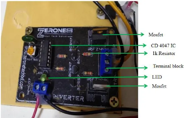
3.5 Inverter Circuit
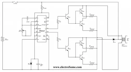
Here is the circuit diagram of a simple 100 watt inverter using IC CD4047 and MOSFET IRF540. The circuit is simple low cost and can be even assembled on a vero board. CD 4047 is a low power CMOS a stable/ mono stable multi vibrator IC. Here it is wired as an stable multi vibrator producing two pulse trains of 0.01s which are 180 degree out of phase at the pins 10 and 11 of the IC. Pin 10 is connected to the gate of Q1 and pin 11 is connected to the gate of Q2. Resistors R3 and R4 prevents the loading of the IC by the respective MOSFETs. When pin 10 is high then Q1 conducts and current flows through the upper half of the transformer primary which accounts for the positive half of the output AC voltage. When pin 11 is high Q2 conducts and current flows through the lower half of the transformer primary in opposite direction and it accounts for the negative half of the output AC voltage.
Figure 3.4: Inverter Circuit.
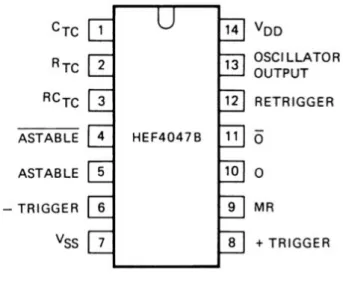
3.5.1 CD 4047
Inverter is a electrical device that converts DC Power to AC. We usually use the word Inverter for the device used in our households for mains power back up. It stores electrical energy in a battery and discharges it when need.
Figure 3.5: IC CD4047.
Our household inverters mainly have two parts, Battery Charging Circuit and Inverter Circuit. Battery charging circuit charges the battery when power is available, which may be mains power, solar power or any other sources and the Inverter Circuit convert the DC power stored in the battery to AC whenever needed.
There are basically three types of inverters,
Square Wave Inverters
Quasi Square Wave or Modified Square Wave Inverters
True or Pure Sine Wave Inverters
For basic requirements we can use Square Wave Inverters which is very simple, low cost and easy to make. But for driving inductive loads pure sine wave inverters are preferred.
Here we are dealing with a Simple Low Power Square Wave Inverter using CD4047. It doesn’t include battery charging circuit which is present in most of the inverters. It can be used to power up to 100w.
Inverter Circuit Diagram using CD4047
Figure 3.6: Simple Inverter Circuit using CD4047.
CD4047 is a low power IC capable of operating in either in astable or monostable mode.
Here it is wired in astable mode. It works by charging a capacitor (C2) through a resistor (RV1) as in every astable multivibrators. Variable resistor (RV1) is provided for adjusting the output frequency to exact 50Hz. The time period of the oscillation is given by the relation T = 4.40*R*C. For detailed working of the IC, please refer its datasheet. CD4047 has two outputs (pins 10 and 11) which are complementary to each other. These square wave pulses are pre amplified by TIP122 transistors.
This amplified current is used to switch 2N3055 transistors to drive the inverter transformer. Two 2N3055 transistors are connected in parallel to increase the current driving capabilities. The Zener Diode ZD1 and capacitor C2 is used to provide constant 9V for the IC. When the output at pin 10 is low, pin 11 will be high Q1, Q3, Q4 turns on, current flows through the upper winding of the transformer and we will get positive half cycle output. When the output at pin 10 is high, pin 11 will be low Q2, Q5, Q6 turns on, current flows through the lower winding of the transformer and we will get negative half cycle output.
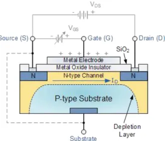
3.5.2 MOSFET
MOSFET’s operate the same as JFET’s but have a gate terminal that is electrically isolated from the conductive channel.
Figure 3.7 : MOSFET
As well as the Junction Field Effect Transistor (JFET), there is another type of Field Effect Transistor available whose Gate input is electrically insulated from the main current carrying channel and is therefore called an Insulated Gate Field Effect Transistor. The most common type of insulated gate FET which is used in many different types of electronic circuits is called the Metal Oxide Semiconductor Field Effect Transistor or MOSFET for short.
The IGFET or MOSFET is a voltage controlled field effect transistor that differs from a JFET in that it has a “Metal Oxide” Gate electrode which is electrically insulated from the main semiconductor n-channel or p-channel by a very thin layer of insulating material usually silicon dioxide, commonly known as glass. This ultra thin insulated metal gate electrode can be thought of as one plate of a capacitor. The isolation of the controlling Gate makes the input resistance of the MOSFET extremely high way up in the Mega- ohms ( MΩ ) region thereby making it almost infinite.
As the Gate terminal is electrically isolated from the main current carrying channel between the drain and source, “NO current flows into the gate”and just like the JFET, the MOSFET also acts like a voltage controlled resistor where the current flowing through the
main channel between the Drain and Source is proportional to the input voltage. Also like the JFET, the MOSFETs very high input resistance can easily accumulate large amounts of static charge resulting in the MOSFET becoming easily damaged unless carefully handled or protected. The symbols and basic construction for both configurations of MOSFETs are shown below.
Figure 3.8: MOSFET diagram
The four MOSFET symbols above show an additional terminal called the Substrate and is not normally used as either an input or an output connection but instead it is used for grounding the substrate. It connects to the main semi conductive channel through a diode junction to the body or metal tab of the MOSFET. Usually in discrete type MOSFETs, this substrate lead is connected internally to the source terminal. When this is the case, as in enhancement types it is omitted from the symbol for clarification.
The line in the MOSFET symbol between the drain (D) and source (S) connections represents the transistors semi conductive channel. If this channel line is a solid unbroken
line then it represents a “Depletion” (normally-ON) type MOSFET as drain current can flow with zero gate biasing potential. If the channel line is shown as a dotted or broken line, then it represents an “Enhancement” (normally-OFF) type MOSFET as zero drain current flows with zero gate potential. The direction of the arrow pointing to this channel line indicates whether the conductive channel is a P-type or an N-type semiconductor device.
3.6 Transformer
A transformer is an electrical device used to change the value of an alternating voltage.
Transformers are widely used in electrical work. They are encountered daily, in industrial, commercial and domestic situations. They vary in size from miniature units used in electronics to huge units used in power stations. The efficient transmission and distribution of electricity throughout the country would be impossible without the use of power transformers.
Center Tapped Step UP Transformer is a general purpose chassis mounting mains transformer. Transformer has 230V primary winding and center tapped secondary winding.
The transformer has flying colored insulated connecting leads ( Approx 100 mm long ).
The Transformer act as step UP transformer reducing AC - 230V to AC - 12V. The Transformer gives outputs of 12V, 12V and 0V. The Transformer's construction is written below with details of Solid Core and Winding. The transformer is a static electrical device that transfers energy by inductive coupling between its winding circuits. A varying current in the primary winding creates a varying magnetic flux in the transformer's core and thus a varying magnetic flux through the secondary winding.
This varying magnetic flux induces a varying electromotive force (E.M.F) or voltage in the secondary winding. The transformer has cores made of high permeability silicon steel. The steel has a permeability many times that of free space and the core thus serves to greatly reduce the magnetizing current and confine the flux to a path which closely couples the winding.
Figure 3.9: Step up Transformer Full Wave Bridge Rectifier
This type of single phase rectifier uses four individual rectifying diodes connected in a closed loop “bridge” configuration to produce the desired output. The main advantage of this bridge circuit is that it does not require a special centre tapped transformer, thereby reducing its size and cost. The single secondary winding is connected to one side of the diode bridge network and the load to the other side as shown below. The filtered full wave rectifier is created from the FWR by adding a capacitor across the output.
Figure 3.10: Full Wave Bridge Rectifier
The four diodes label led D1 to D4 are arranged in “series pairs” with only two diodes conducting current during each half cycle. During the positive half cycle of the supply, diodes D1 and D2 conduct in series while diodes D3 and D4 are reverse biased and the current flows through the load as shown below.
The Positive half Cycle: During the negative half cycle of the supply, diodes D3 and D4 conduct in series, but diodes D1 and D2 switch “OFF” as they are now reverse biased. The current flowing through the load is the same direction as before.
Figure 3.11: Positive Half Cycle of Full Wave Bridge Rectifier
The Negative Cycle:
Figure 3.12: Negative Half Cycle of Full Wave Bridge Rectifier
As the current flowing through the load is unidirectional, so the voltage developed across the load is also unidirectional the same as for the previous two diode full-wave rectifier.
3.7 High Speed Pump
Figure 3.13: High Speed Pump
Feature:
Pump Operating Voltage: 12V - 24V
Power: 120W Max
Working Pressure: 160Psi (10.5 Bar) Cutoff
Cutoff Automatic Switch
Flow (MAX): 10L/min
Pressure Adjustable Copper Head Water Spray
Water Pressure Limit : Adjustable
Sprayers Size : 20cm
Spray Distance: 9 m
Thread Diameter: 1.5cm
Main Material: Copper, Plastic
Power supply Voltage: 12V DC
Power supply Current: 5A
3.8 Digital Volt-ammeter
A voltmeter is an instrument used for measuring electric potential difference between two points in an electric circuit. It is connected in parallel. It usually has a high resistance so that it takes negligible current from the circuit. An ammeter (abbreviation of Ampere meter) is a measuring instrument used to measure the current in a circuit. Electric currents are measured in Amperes (A), hence the name. The ammeter is usually connected in series with the circuit in which the current is to be measured. An ammeter usually has low resistance so that it does not cause a significant voltage drop in the circuit being measured.
Figure 3.14: Voltmeter ammeter dual display
Features:
Display color: Red & Blue LED (dual display).
Display: 0.28″ LED digital.
Operating voltage: DC 4.5 ~ 30V.
Measure voltage: DC 0 ~ 100V.
Minimum resolution (V): 0.1V.
Refresh rate: ≥500ms / times.
Measure accuracy: 1% (± 1 digit).
Minimum resolution (A): 0.01A.
Operating Current: <20mA.
Measure current: 10A (direct measurement, built-in shunt).
Operating temperature: -10 to 65°c.
Operating Humidity: 10 to 80% (non-condensing).
Mounting cutout: 45.5mm x 26.1mm.
3.9 The Smoothing Capacitor
When there is a potential difference across the conductors (e.g., when a capacitor is attached across a battery), an electric field develops across the dielectric, causing positive charge (+Q) to collect on one plate and negative charge (-Q) to collect on the other plate.
If a battery has been attached to a capacitor for a sufficient amount of time, no current can flow through the capacitor. However, if an accelerating or alternating voltage is applied across the leads of the capacitor, a displacement current can flow.
Figure 3.15: Capacitor
An ideal capacitor is characterized by a single constant value for its capacitance.
Capacitance is expressed as the ratio of the electric charge (Q) on each conductor to the potential Difference (V). The SI unit of capacitance is the farad (F), which is equal to one coulomb per volt (1 C/V). Typical capacitance values range from about 1 pF (10−12 F) to about 1 mF (10−3 F). The capacitance is greater when there is a narrower separation between conductors and when the conductors have a larger surface area.
In practice, the dielectric between the plates passes a small amount of leakage current and also has an electric field strength limit, known as the breakdown voltage. The conductors and leads introduce an undesired inductance and resistance. Capacitors are widely used in electronic circuits for blocking direct current while allowing alternating current to pass. In analog filter networks, they smooth the output of power supplies. In resonant circuits they tune radios to particular frequencies. In electric power transmission systems, they stabilize voltage and power flow.
The full-wave bridge rectifier however, gives us a greater mean DC value (0.637 Vmax) with less superimposed ripple while the output waveform is twice that of the frequency of the input supply frequency. We can improve the average DC output of the rectifier while at the same time reducing the AC variation of the rectified output by using smoothing capacitors to filter the output waveform. Smoothing or reservoir capacitors connected in parallel with the load across the output of the full wave bridge rectifier circuit increases the average DC output level even higher as the capacitor acts like a storage device as shown below. Too low a capacitance value and the capacitor has little effect on the output waveform. But if the smoothing capacitor is sufficiently large enough (parallel capacitors can be used) and the load current is not too large, the output voltage will be almost as smooth as pure DC.
Figure 3.16: The Smoothing Capacitor with Full Bridge Rectifier
3.10 Resistor
Resistors are electronic components which have a specific, never-changing electrical resistance. The resistor's resistance limits the flow of electrons through a circuit. They are passive components, meaning they only consume power (and can't generate it). Resistors are usually added to circuits where they complement active components like op-amps, micro controllers, and other integrated circuits. Commonly resistors are used to limit current, divide voltages, and pull-up I/O lines.
The electrical resistance of a resistor is measured in ohms. The symbol for an ohm is the greek capital-omega: Ω. The (somewhat roundabout) definition of 1Ω is the resistance between two points where 1 volt (1V) of applied potential energy will push 1 ampere (1A) of current. As SI units go, larger or smaller values of ohms can be matched with a prefix like kilo-, mega-, or giga-, to make large values easier to read. It's very common to see resistors in the kilohm (kΩ) and megaohm (MΩ) range (much less common to see miliohm (mΩ) resistors). For example, a 4,700Ω resistor is equivalent to a 4.7kΩ resistor, and a 5,600,000Ω resistor can be written as 5,600kΩ or (more commonly as) 5.6MΩ.
All resistors have two terminals, one connection on each end of the resistor. When modeled on a schematic, a resistor will show up as one of these two symbols:
Figure 3.17: Two common resistor schematic symbols
3.11 Proteus Software
The Proteus Design Suite is a proprietary software tool suite used primarily for electronic design automation. The software is used mainly by electronics design engineers and technicians to create schematics and electronics prints for manufacturing printed circuit boards.
Figure 3.18: Our Project Design in Proteus Software
The first version of what is now the Proteus Design Suite was called PC-B and was written by the company chairman, John Jameson, for DOS in 1988. Schematic Capture support followed in 1990 with a port to the Windows environment shortly thereafter.
Mixed mode SPICE Simulation was first integrated into Proteus in 1996 and micro- controller simulation then arrived in Proteus in 1998. Shape based auto routing was added in 2002 and 2006 saw another major product update with 3D Board Visualization.
More recently, a dedicated IDE for simulation was added in 2011 and MCAD import/export was included in 2015. Support for high speed design was added in 2017.
Feature led product releases are typically biannual, while maintenance based service packs are released as required.
CHAPTER 4
METHODOLOGY
4.1 Our methodologies for the project
Our methodologies for the project:
Creating an idea for design and construction of aPower Generation Using Hydro Turbine System. And designing a block diagram & circuit diagram to know which components we need to construct it.
Collecting all the components of our system.
Setting up all the components in a PCB board & then soldering. Lastly, assembling all the blocks in a board and to run the system & for checking purposes.
4.2 Block Diagram
Figure 4.1: Block Diagram of Our System
4.3 Schematic Diagram
The schematic diagram here is representing the electrical circuit and the components of the project. Here we have used standardized symbols and lines.
Figure 4.2: Schematic Diagram of the Circuit
4.4 Working Principle
We will be powered by this battery system. So here we have a 12 volt battery. The connection of the high speed pump with the battery will turn the turbine. A generator motor is attached to the turbine. This will generate more power as the turbine rotates. An LED indicator is fitted to see if power is being generated. When the generator motor turns, power is generated from it and the LED will blink . The generated power will be stored in the battery. The current and voltage generated will be shown on a volt emitter meter. This generated DC voltage will convert AC to load with the help of inverter circuit. This is the main purpose of our system.
4.5 Our Final System View
Figure 4.3: Our Final System Overview
CHAPTER 5
RESULT AND DISCUSSION
5.1 Result
Now, it’s time to talk about the results. We have written our commands using the Arduino IDE and the following things can happen:
After power this project then it will be able to operate.
Here when we start our high speed pump with a battery.
The the water flow hit the turbine belt and rotate it.
For the reason of rotating the generator motor there produce energy.
The generated power will be stored in the battery.
The current and voltage generated will be shown on a volt emitter meter.
This generated DC voltage will convert AC to load with the help of inverter circuit.
Graph:
Figure 5.1: Efficiency Curve for a Francis turbine (Efficiency Vs Load)
Figure 5.2: Efficiency vs Flow Rate Carve
5.2 Discussion
While working on our project, we did face some difficulties as it is a very complex system but the end results, we came up with were quite satisfactory. We have put the whole system through several tasks to validate our work and also have taken necessary notes for future improvements. Some future recommendations that we have involves improvement in system design and wiring, adding features for more efficient.
CHAPTER 6
APPLICATION AND COST ANALYSIS
6.1 Project Cost Analysis
Table 01: Project Cost Analysis Sl.
no
Particulars Specification Qty. Unit Price (Taka)
Total Price (Taka)
1 Motor 1 700 700
2 Battery 12 Volt 1 1150 1150
3 Inverter Circuit 100 Watt 1 250 250
4 Water Container 15L 1 230 230
5 Volt-ammeter Digital 1 340 340
6 Turbine Hand Made 1 100 100
7 Transformer 3 Amp 1 360 360
8 High Speed Pump 12V 1 2500 2500
9 Others 1050
Total 6680/=
6.2 Advantages
There are many advantages of our project because of its accuracy. Some of the advantages are pointed out below:
• Hydro power is decentralized,
• Its Renewable,
• Robust
• Simple technology
• Takes small amount of flow to create power
• Environmentally friendly.
• No Oil consumption.
• Installation is simplified very much.
• Simple construction
• Easy of operation.
6.3 Applications
Some of the application areas of the project has been pointed out below:
This System Can Be Widely Used for power generation system .
Water turbines have been used for industrial power & power grids since the 19th century.
The main drawback of a water turbine is its size because it restricts the flow rate & the head can be controlled. The movement from these turbines to current turbines took about several years. So, this development occurred throughout the Industrial revolution with scientific methods & principles. They also used different new materials & designing techniques to develop these turbines. This article discusses an overview of a water turbine and it’s working.
Turbines are fundamentally work based on Isaac Newton’s third law because this law states that for each action there is also an equivalent and reverse reaction. Generally, Turbines are fixed in position so once water supplies throughout it then there is a drop
or air, the working principle is similar, the medium will move faster, the pressure is greater & the turbine spins will be faster.
6.4 Limitation
Every system have some limitations that’s why limitations of our project is given below.
Without turbine rotation there is no produce electricity.
CHAPTER 7
CONCLUSION
7.1 Conclusion
Hydro is a major primary source of energy in Bangladesh especially in the north-eastern hilly regions. Hydro power continues to grow around the world, it is important to show the public how feasible hydro systems actually are in a suitable site. The only requirements for hydro power are water sources, turbines, generators, proper design and installation, which not only helps each individual person but also helps the world and environment as a whole.
Run-of-river hydro turbine schemes generate electricity when the water is available and provided by the river. When the river dries-up and the flow falls below predetermined amount or the minimum technical flow for the turbine, generation will ceases.Necessity of exploring energy from alternative sources and impact of hydro as an alternative source has been presented.
7.2 Future Scope
We are thinking about adding many features to our project in the future to get more desirable outcomes. Some of the steps that we are thinking about taking are given below:
In future, we are looking forward to improving our whole system design to make it more efficient.
In future, we are thinking using in real life project.
REFERENCE
[1] Deshmukh and Bilolikar: "Basic design aspects of micro-hydro-power plant and its potential development in Malaysia", National Power and Energy Conference (PECon) Proceedings, Kuala Lumpur, Malaysia, 2006.
[2] Monteiro: "Layman's guidebook on how to develop a small hydro site", Published by the European Small Hydro power Association (ESHA), Second edition, Belgium, June, 2005.
[3] Zhou Quan: "Micro-hydro-power", Resource Assessment Handbook, An Initiative of the Asian and Pacific Center for Transfer of Technology, September, 2002.
[4] Khator and leung : European Small Hydropower Association (ESHA): "Energy recovery in existing infrastructures with small hydro power plants", Sixth Framework Programme, Publication by Mhylab, Switzerland, June, 1997.
[5] Monteiro and Anoop Kumar: "Small hydro power – A review", International Journal of Thermal Technologies, Vol. 1, NO. 1, pp. 107-110, December, 2005.
[6] Jewell, Grossardt and Bailey: "Feasibility study of microhydro-electric power generation at Sapchari Waterfall, Khagrachari, Bangladesh", Journal of Applied Science, Vol. 9, No. 2, pp. 372- 376, 2006.
[7] Tram , Wall and Bard Jackson: "State-of-the-art in mini-hydro electrical design", Renewable Energy Review Journal, Vol. 4, No. 2, pp. 47-55, December, 1988.
[8] Urban, Bandars and Moll et al.: "Appropriate low head microhydro systems for Bangladesh", Second International Conference on Electrical and Computer Engineering (ICECE), Dhaka, Bangladesh, pp. 216-219, 26-28December, 2009.
[9] Kaundinya, Balchandra and Ravindranathet al.: "Application of cross-flow turbine in off-grid Pico-hydro renewable energy systems", Proceeding of the American-Math 10 Conference on Applied Mathematics, pp. 519- 526, 2009.
![Figure 1.1: Operation of a water wheel [1]](https://thumb-ap.123doks.com/thumbv2/filepdfnet/11889446.0/10.892.259.639.628.861/figure-1-1-operation-of-a-water-wheel.webp)