UNIVERSITI TEKNIKAL MALAYSIA MELAKA (UTeM)
FAKULTI KEJURUTERAAN ELEKTRIK (FKE)
PROJEK SARJANA MUDA
BEKU 4933
TO STUDY, DESIGN & DEVELOP A SMALL SCALE PROTOTYPE OF MICRO HYDRO SYSTEM WITH AUTOMATIC VALVE CONTROL
Tie Chin Ho
“I hereby declare that I have read through this report entitle “To Study, Design & Develop A Small Scale Prototype Of Micro Hydro System With Automatic Valve Control”
and found that it has comply the partial fulfilment for awarding the degree of Bachelor of Electrical Engineering (Industrial Power)”
Signature :
TO STUDY, DESIGN & DEVELOP A SMALL SCALE PROTOTYPE OF MICRO HYDRO SYSTEM WITH AUTOMATIC VALVE CONTROL
TIE CHIN HO
A report submitted in partial fulfillment of the requirements for the degree
of Electrical Engineering (Industrial Power)
Faculty of Electrical Engineering
UNIVERSITI TEKNIKAL MALAYSIA MELAKA
I declare that this report entitle “To Study, Design & Develop a Small Scale Prototype of Micro Hydro System with Automatic Valve Control” is the result of my own research except as cited in the references. The report has not been accepted for any degree and is not
concurrently submitted in candidature of any other degree.
Signature :
ACKNOWLEDGEMENT
I wish to express my deepest gratitude to my supervisor, Mr. Khairul Anwar Bin
Ibrahim for guiding me in this project. The success of this PSM is highly influenced by his information, suggestions and ideas. His willingness to assist me through his guidance, advices, and continued support has been a great motivation for me to excel in my project. My fellow undergraduate students should also be recognized for their support. My sincere appreciation also extends to all my colleagues and others who have provided assistance at various occasions. Their views and tips are useful indeed.
ii
ABSTRACT
ABSTRAK
iv 2.3 Operation Principles Of Micro Hydropower
Generation
6
2.4 Elements of Micro Hydropower Plant 8 2.4.1 Site Layouts 9 2.4.2 Types of Micro Hydropower Plants’
Turbines
10
3 METHODOLOGY 15 4.1.3 Generator Load Performance 39 4.1.4 Governor performance 41
4.2 Discussion 43
5 CONCLUSION & RECOMMENDATION 45
5.1 Conclusion 45
5.2 Recommendation 46
vi
LIST OF TABLE
TABLE TITLE PAGE
2.1 Micro Hydro Potential Sites by State 5 2.2 Different type of turbine 11 2.3 Comparison between conventional governor controller and electronic
load controller
14
LIST OF FIGURE
FIGURE TITLE PAGE
2.1 Energy conversion of micro hydropower generation 6 2.2 Basic scheme of a micro hydropower plant 8 2.3 Four most common layouts for MHPP 9
2.4 Pelton Propeller 10
2.5 2 example of Francis propeller; (a) open-flume francis, (b) spiral-case francis
11
2.6 Submersible-propeller turbine 11 2.7 Typical micro-hydropower plant’s electric components 12 3.1 Flow Chart Of Methodology 15 3.2 Centrifugal pump and pressure tank 16 3.3 Water flow system 17 3.4 The piping system of the project 17
3.5 Impulse turbine 18
3.6 Voltage (V) vs Rotation Speed (RPM) of Ginlong GL-PMG-500A
19
viii
3.16 Circuit diagram of motor controlled by relays 25 3.17 Overall circuit of the governor system 26 3.18 Program that written by MikroC and burnt in PIC16F877A 27 3.19 Circuit of governor system 29 3.20 Appearance of the controller of governor system 29 3.21 The testing load circuit 30 3.22 Fluke 43B power quality analyser 30 4.1 Pressure of water when the pump operate 33 4.2 Hydraulic power produced (W) Vs Number of nozzles 35 4.3 Open circuit voltage of generator with 1 nozzle 38 4.4 Open circuit voltage of generator with 2 nozzles 37 4.5 Open circuit voltage of generator with 3 nozzles 38 4.6 Summary of open circuit voltage versus the RPM with different
numbers of nozzle
39
CHAPTER 1
INTRODUCTION
1.1 Project Background
Renewable energy has become a hot issue now in nowadays due to climate change concerns, coupled with high oil prices increasing government support. Renewable energy is energy which comes from natural resources such as sunlight, wind, water, tides, and geothermal heat, which can naturally replenished [1].
Water has been used as an energy source for thousands of years, since ancient civilizations using water to drive mills through the use of water wheels. Technology has been improved from time to time, and the potential for water as a power source continues to be important. Large-scale example such as the Three Gorges Dam in China is used to power large-scale projects [2].
2
1.2 Problem Statement
Normally, micro hydro system is designed with the fixed flow water to push the turbine of the alternator. However, this design will cause problem when few situation happen:
When the load in system increases, the speed of alternator will drop, causing the voltage and frequency of the power supply to also drop.
During raining day, the flow or pressure of water to the turbine will increase. This cause the voltage and frequency of the alternator will increase. This will damage the device in the system as well. Current solution is to switch on the dumping load when higher voltage produced is noticed.
1.3 Project Objective
To study, to design a micro hydro system and the parameter that need to be considered to make the system to success.
To develop a small scale prototype of micro hydro system with automatic valve control.
1.4 Scope of The Project
Develop a small scale prototype of micro hydro system with automatic valve control which can control the flow rate of the water that entering to the turbine.
4
CHAPTER 2
LITERATURE REVIEW
2.1 Micro Hydropower
Micro hydropower is a renewable energy which harvests the kinetic energy from streaming waters, then converts to electrical energy on a small scale. Generally, a moving stream of water turns turbine blades which are connected to a shaft that spins a generator to produce electricity [4]. It is a green energy with zero carbon emission during the operation. MHPP convert potential energy from falling water into electric energy. Water is channelized from a higher level to a lower level which the resulting potential energy of water is used to do work. The water head is used to move a mechanical component (turbine) then that movement involves the conversion of the potential energy of the water into kinetic energy to spin the turbine. The turbine is connected to a shaft that spins a generator [5].
2.2 Potential of MHPP in West Malaysia
Malaysia is a tropical country with average rainfall of 2540 millimetre (mm) in Peninsula and blessed with richly supplied streams and rivers flowing from the highland areas [7]. Some researches had been done and found out that West Malaysia has the potential to implement micro hydropower plant to generate electricity with total estimated available power is 20407.3 kW [7] . Table 2.1 show about potential micro hydropower plant side by state:
6
2.3 Operation Principles Of Micro Hydropower Generation
Basically, micro hydropower generation is converting one form of energy to electrical energy. The most common convertion of energy at micro hydropower plant is as shown in Figure 2.1:
Figure 2.1: Energy conversion of micro hydropower generation
The potential energy is the energy stored in the water due to its position. When the water flows from higher position to lower position, the energy is converted from the potential energy to kinetic energy. When the water hit the turbine and spins the generator, the generator converts the kinetic energy to electric energy. The equation of the energy conversion is as per Equation 2.1:
E (energy release in joules) = mgh [4] (2.1)
m = mass of the water
g = gravitational acceleration = 9.81m/s2 h = vertical distance h, or the head
Head, h is defined as the elevation difference between the water source and the turbine. The mass of the water, m also can be defined as water density, r times its volume v,
where the water density is 1000 kg/m3. When substituted to Eq. 2.1, the energy release
equals to as Equation 2.2:
E (joules) = vrgh[4] (2.2)
Power, P is defined as energy per second (P = E/s), the energy of water entering the hydroelectric turbine is as per Equation 2.3:
P (J/s) = rvgh/s W (J/s = W) [4] (2.3) R = 1000 kg/m3
v/s = flow rate, Q
Flow is the volumetric measure of moving water, in cubic meter per second. One method which can measure water flow is called the container method, in which water is collected in a bucket for certain duration of time. The amount of collected water in the container is divided by the time it takes to fill the bucket [4]. So, energy contain in the flow of water is as per Equation 2.4
Pnet = e × Q × 9.8×h kW [4] (2.4)
Where, e = efficiency
For practical purposes, the formula applied becomes as in Equation 2.5
Pnet = 0.5 ×Q × 10 ×h kW [4] (2.5)
8
2.4 Elements of Micro Hydropower Plant
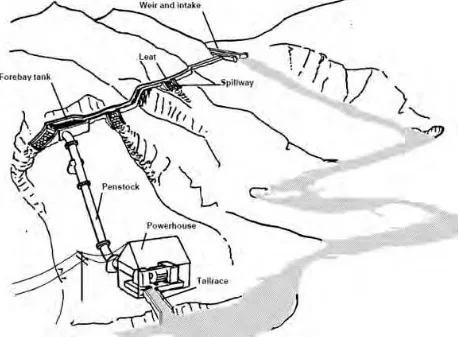
The scheme of a micro hydropower plant is shown in Figure 2.2 can be summarised as follows [8]:
Water is taken from the river by through an intake at a weir.
Before water flow to the turbine, the water passes through a forebay tank where the water is slowed down sufficiently for suspended particles to be filtered out.
Penstock will convey the water from the forebay tank to the turbine, which is enclosed in the powerhouse together with the generator and control equipment.
Finally, the water will release back to the river.
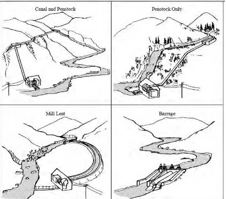
2.4.1 Site Layouts
In practice, sites for micro hydropower plant vary greatly depend on the landscape. They might need to build at mountain area where there are fast-flowing mountain streams or lowland areas with wide rivers. The four most common layouts for a micro hydropower plant are shown in Figure 2.3:
10
2.4.2 Types of Micro Hydropower Plants’ Turbines
Turbines are used to convert the energy contained in a continuous flow of fluid into rotational mechanical energy of a shaft. In micro hydropower plant, turbines are used to connect with the shaft of the generator to spin to generate electricity. There are few types of turbines use in micro hydropower plant, which are impulse-type turbine, reaction-type turbine and submersible-propeller turbines [4].
For impulse-type turbine, which is shown in Figure 2.4, water strikes the turbine runner and pushes it to rotate like the water mills. These types of water-propelled electrical generators work best in sites with high head. The best known impulse-type propeller is called Pelton propeller [4]. Impulse-type propeller will be used as turbine in this project.
Figure 2.4: Pelton Propeller[8]
![Table 2.1: Micro Hydro Potential Sites by State[7]](https://thumb-ap.123doks.com/thumbv2/123dok/574290.68066/19.595.88.536.285.462/table-micro-hydro-potential-sites-state.webp)

![Figure 2.4: Pelton Propeller[8]](https://thumb-ap.123doks.com/thumbv2/123dok/574290.68066/24.595.223.380.325.466/figure-pelton-propeller.webp)
