AN IoT BASED SMART HOME SYSTEM BY
MD. TOUFIK TAJ ID: 181-15-10646 ANANNA RANI DAS
ID: 181-15-10810
This Report Presented in Partial Fulfillment of the Requirements for the Degree of Bachelor of Science in Computer Science and Engineering.
Supervised By
Md. Sadekur Rahaman Assistant Professor
Department of CSE
Daffodil International University
Co-Supervised By
Mst. Eshita Khatun Lecturer (Senior Scale)
Department of CSE
Daffodil International University
DAFFODIL INTERNATIONAL UNIVERSITY
DHAKA,BANGLADESH SEPTEMBER2022
©Daffodil International University i
APPROVAL
This Project/internship titled “AN IoT BASED SMART HOME SYSTEM”, submitted by Md. Toufik Taj, ID No: 181-15-10646 and Ananna Rani Das, ID No:
181-15-10810 to the Department of Computer Science and Engineering, Daffodil International University has been accepted as satisfactory for the partial fulfillment of the requirements for the degree of B.Sc. in Computer Science and Engineering and approved as to its style and contents. The presentation has been held on 12 September 2022.
BOARD OF EXAMINERS
________________________
Dr. Sheak Rashed Haider Noori
Associate Professor and Associate Head
Department of Computer Science and Engineering Faculty of Science & Information Technology Daffodil International University
Chairman
________________________
Raja Tariqul Hasan Tusher Assistant Professor
Department of Computer Science and Engineering Faculty of Science & Information Technology
Internal Examiner
________________________
Md. Sabab Zulfiker Senior Lectuer
Department of Computer Science and Engineering Faculty of Science & Information Technology Daffodil International University
Internal Examiner
______________________
Dr. Mohammad Shorif Uddin Professor
Department of Computer Science and Engineering Jahangirnagar University
External Examiner
©Daffodil International University ii
DECLARATION
We hereby declare that, this project has been done by us under the supervision of Md.
Sadekur Rahman, Assistant Professor, Department of CSE Daffodil International University. We also declare that neither this project nor any part of this project has been submitted elsewhere for award of any degree or diploma.
Supervised by:
Md. Sadekur Rahman Assistant Professor Department of CSE
Daffodil International University Co-Supervised by:
Mst. Eshita Khatun Lecturer(Senior Scale) Department of CSE
Daffodil International University Submitted by:
Md. Toufik Taj ID: 181-15-10646 Department of CSE
Daffodil International University
Ananna Rani Das ID: 181-15-10810 Department of CSE
Daffodil International University
©Daffodil International University iii
ACKNOWLEDGEMENT
First we express our heartiest thanks and gratefulness to Almighty God for His divine blessing making us possible to complete the final year project/internship successfully.
We are really grateful and wish our profound our indebtedness to Md. Sadekur Rahman,Assistant Professor, Department of CSE Daffodil International University, Dhaka. Deep Knowledge & keen interest of our supervisor in the field of “Embedded System & IoT ” to carry out this project. His endless patience, scholarly guidance, continual encouragement, constant and energetic supervision, constructive criticism, valuable advice, reading many inferior drafts and correcting them at all stages have made it possible to complete this project.
We would like to express our heartiest gratitude to Professor Dr. Touhid Bhuiyan, Head, Department of CSE, for his kind help to finish our project and also to other faculty members and the staff of CSE department of Daffodil International University.
We would like to thank our entire course mate in Daffodil International University, who took part in this discussion while completing the course work.
Finally, we must acknowledge with due respect the constant support and patience of our parents.
©Daffodil International University iv
ABSTRACT
We are living in an era of science and technology where we cannot even think a single day without modern technology. Electricity is one of the greatest invention of science which is now available all over the world. So, saving electricity with a smart system is also required for living a comfortable life. The project's goal is to create an embedded system that can control every electric machines with the help of internet. Furthermore, this embedded system project can detect flammable gas and ring the cautionary alarm in the selected place. So, by this device, safety can be assured at home or in any place.
The automation system can save the waste of electricity with its sensor system, as well as assure the safety of the place from fire-accidents caused by gas. The entire system can be defined as a smart automation system which is essential for saving electricity as well as home safety, especially for this contemporary situation of our country.
©Daffodil International University v
TABLE OF CONTENTS
CONTENTS PAGE
Board of examiners i
Declaration ii
Acknowledgements iii
Abstract iv
List of Figures vii
List of Table viii
CHAPTER 1: INTRODUCTION 01-02
1.1 Overview 1
1.2 Background and Present State 1
1.3 Statement of the project 2
1.4 Summary 2
1.5 Objectives 2
1.6 Estimated Cost 2
CHAPTER 2: BACKGROUND 03-04
2.1 Terminologies 3
2.2 Related Works 3
2.3 Scope of the Problem 4
2.4 Challenges 4
CHAPTER 3: REQUIRMENT SPECIFICATION 05-08
3.1 Introduction 5
3.2 Block diagram 5
3.2 Block diagram description 5
3.3 Flowchart diagram of our project 6
3.4 Circuit diagram 7
3.4 Working process of our circuit diagram 7
3.5 List of components used in circuit 8
CHAPTER 4: HARDWARE SPECIFICATION 09-16
4.1 Introduction 9
©Daffodil International University vi
4.2 Bread Board 9
4.3 NodeMCU 10
4.4 Pinout Configuration 11
4.5 Relay Module: 12
4.6 Wire: 12
4.7 Bulb 13
4.8 Software Components: 13
4.8.1 Arduino IDE 14
4.8.2BLYNK: 15
4.9 Summary 16
CHAPTER 5: WORKING PROCEDURE 17
5.1 Overview 17
5.2 Automatic Control 17
5.3 Manual Control 17
5.4 Communication 17
5.5 Estimated Cost 17
CHAPTER 6: RESULT AND APPLICATION 18-20
6.1 Result 18-19
6.2 Application 20
6.3 Advantages 20
6.4 Disadvantages 20
CHAPTER 7: FUTURE WORK AND CONCLUSION 21
7.1 Future Work 21
7.2 Limitation 21
7.3 Conclusion 21
REFERENCES 22
PLAGIARISM SCREEN SORT 23
©Daffodil International University vii
LIST OF FIGURES
FIGURES
PAGES
Figure 3.1 Block Diagram of our hardware part 5
Figure 3.2 Hardware device flowchart diagram 6
Figure 3.3 Our project Circuit diagram. 7
Figure 4.1 Project Board 9
Figure 4.2 NodeMCU 10
Figure 4.3 Relay Module 12
Figure 4.4 Wire 12
Figure 4.6 Bulb 13
Figure 4.7 Arduino IDE 14
Figure 4.8 Blynk 15
Figure 6.1 Project Picture 18
Figure 6.2 Blynk Web LayOut 19
Figure 6.3 Blynk App LayOut 19
©Daffodil International University viii
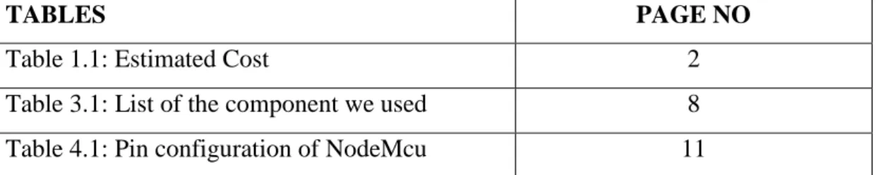
LIST OF TABLES
TABLES PAGE NO
Table 1.1: Estimated Cost 2
Table 3.1: List of the component we used 8
Table 4.1: Pin configuration of NodeMcu 11
©Daffodil International University 1
CHAPTER 1 Introduction
1.1Overview
Bangladesh is a developing country with 164 Million of population. Since the population is quite more than the surface of our country, so it is quite normal to face various type of problem including transport system, agricultural, electrical etc.
Electricity problem has become one of the major problems during this time in our country. Recently, in the context of 2022, the problem of load-shedding has been increased in an unpleasant level. So, saving electricity to prevent the load-shedding issue has become an important matter at present. We can always keep an eye to the electric machine by this device. Whenever electricity is wasted in any place, we can switch it off by internet from anywhere of the country. By this, the electricity wasting will decrease and our life will become easier.
1.2 Background and Present State
According to the latest update, Bangladesh Government has declared to set one or two hours of load-shedding in listed areas, especially in north, which faces four-five hours of load-shedding each day. The government has already announced a schedule-based power cuts to reduce the electricity crisis. People often forget about the waste of electricity because of various reasons or business. So, this has become one of the major reasons behind the load-shedding issue. Moreover, in this era of technology, manual system in works is being decreased day by day. We are getting involved in remote- controlled term. In this aspect, automation system is really an effective and essential technique for controlling the electricity, which also contains the meaning of comfortness of user. At present, internet is available in everywhere. This is the high time we can use the best of the technology. By this device, not only a normal person will get benefitted, but also a physically disabled person can control his/her home very easily. This will play an important role in our society.
©Daffodil International University 2 1.3 Statement of the Project
The project is an automation system which is made in low cost that can control the electrical machines with the help of mobile phone and internet from any place. The embedded system can turn ON and OFF the switch of light by mobile phone.
1.4 Summery
Electricity problem is one of the major issues in Bangladesh at present. This IoT project is made in a low cost which assures both savings and safety. The device confirms the comfortness of the user as he/she can control the electrical machines by his/her mobile phone with the help of internet from any place.
1.5 Objectives
The principal target of this project is to spread the use of technology in a friendly cost and to make our life easier. The people from all classes will be benefited with this device. Our target is to make a wireless device by which electrical machines can be controlled from anywhere. For this, internet is needed, which is available in every home. Our device can be controlled by monitoring from any place by mobile phone. If internet connection is disconnected for any inconvenience, we have kept the switch system for manually controlling as alternative. Connecting the device with Wi-Fi, from children to old and ill, all classes’ people can enjoy the benefits of the usage of this device.
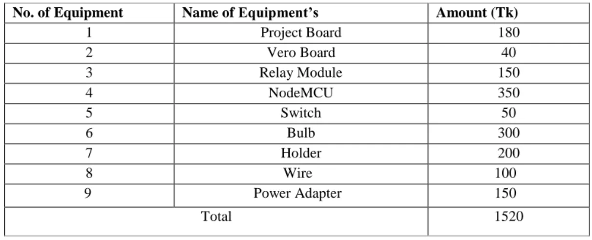
1.6 Estimated Cost
Table 1.1: Estimated Cost
No. of Equipment Name of Equipment’s Amount (Tk)
1 Project Board 180
2 Vero Board 40
3 Relay Module 150
4 NodeMCU 350
5 Switch 50
6 Bulb 300
7 Holder 200
8 Wire 100
9 Power Adapter 150
Total 1520
©Daffodil International University 3
CHAPTER 2 BACKGROUND
2.1 Terminologies
It’s an IoT integrated web & app based system for smart home system. Mainly this program will run on a server linked with domain hosting. And the hardware section performance by local hosting. With this we can control home from anywhere with the help of internet.
2.2 Related Works
❖The main objective of home automation and security system is to control home appliances by using different techniques like android application, web pages, GSM when a person is away from home [1].
❖The project proposes an efficient implementation for IoT (Internet of Things) used for monitoring and controlling the home appliances via World Wide Web. Home automation system uses the portable devices as a user interface. They can communicate with home automation network through an Internet gateway, by means of low power communication protocols like Zigbee, Wi-Fi etc. This project aims at controlling home appliances via Smartphone using Wi-Fi as communication protocol and raspberry pi as server system [2].
❖ In recent years, the advancements in Information and Communication Technology (ICT) are mainly focused on the Internet of Things (IoT). In a genuine situation, IoT based administrations work on the homegrown climate and are utilized in different applications. Home robotization based IoT is adaptable and well known applications.
In home robotization, all home apparatuses are organized together and ready to work without human contribution. Home mechanization gives a massive change in human existence which gives shrewd working of home machines. This spurred us to foster another arrangement which controls a few home machines like light, fan, entryway containers, energy utilization, and level of the Gas chamber utilizing different sensors like LM35, IR sensors, LDR module, Node MCU ESP8266, and Arduino UNO. [3].
©Daffodil International University 4
❖ Liquid petroleum gas (LPG) is commonly used in homes for central heating, hot- water, gas-fires, cooking, and in mobile heaters for leisure activities such as boats, caravans and barbecues. This energy source is primarily composed of propane and butane which are highly flammable chemical compounds. LPG leaks can happen, though rarely, inside a home, commercial premises or in gas powered vehicles. Leakage of this gas can be dangerous as it raises the risk of building fire or an explosion [4].
2.3 Scope of the problem
The system is the scope in this era to solve the problem. Nowadays, IoT lead the develop country. So I can barely say, this is the era we have to improve and make our country more digital and smart.
2.4 Challenges
The main challenging thing is reducing the cost but it’s comparatively flexible. Hope best and we will work on it in future to reduce cost. Also accepting all challenges to overcome related to our system.
©Daffodil International University 5
CHAPTER 3
Requirement Specification
3.1 Introduction
In this chapter, we will discuss our project which is IoT based service providing the system with web integration using the ng website web controller option. Here will show some work like block diagram of our project, circuit diagram, Flowchart, and is three to components we used in this project.
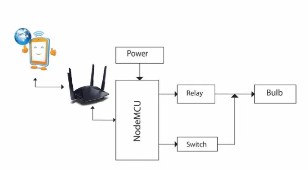
3.2 Block diagram:
This is our project block diagram. Here we show how our project works.
Figure 3.1: Block Diagram of our hardware part
3.2.1 Block diagram description
As we can saw that firstly our device connect with web platform through router connection because in our microcontroller has on board wifi module which can connect our device with internet. Then in the next microcontroller connect with relay and sensor.
Relay connected with Bulb and it make bulb ON/OFF. Switch connected with NodeMCU and it can control the system manually if needed.
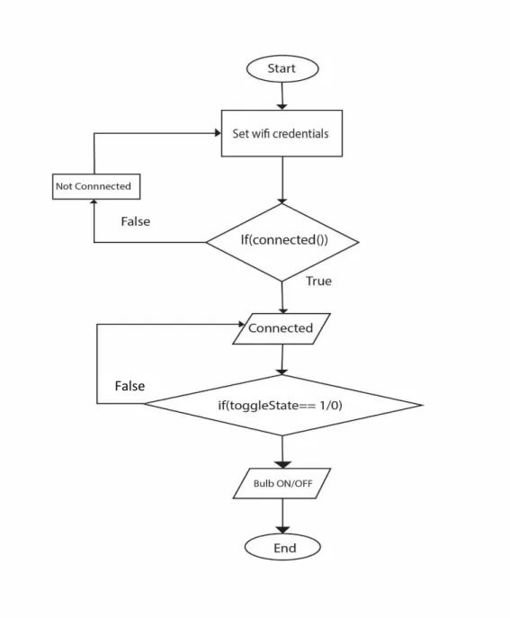
©Daffodil International University 6 3.3 Flowchart Diagram of our project:
Here we depicted our system with flowchart
Figure 3.2 Hardware device flowchart diagram False
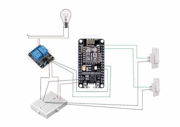
©Daffodil International University 7 3.4 Circuit diagram:
Here we graphically represent our electrical circuit
Figure 3.3 Our project Circuit diagram.
3.4.1 Working process our circuit diagram
In this circuit diagram, each pins of the two switches are serially connected with the D1 and D2 pins of NodeMCU and other pins are connected with ground. The A0 pin of MQ2 sensor is connected with the A0 pin of NodeMCU. Ground and VCC is serially connected with G and VCC pin. D6 and D7 pins are serially connected with the In1 and In2 of relay module. VCC of relay and ground pin are serially connected with VCC and ground. The positive pin of the buzzer is connected with D5 and the other pin is with ground.
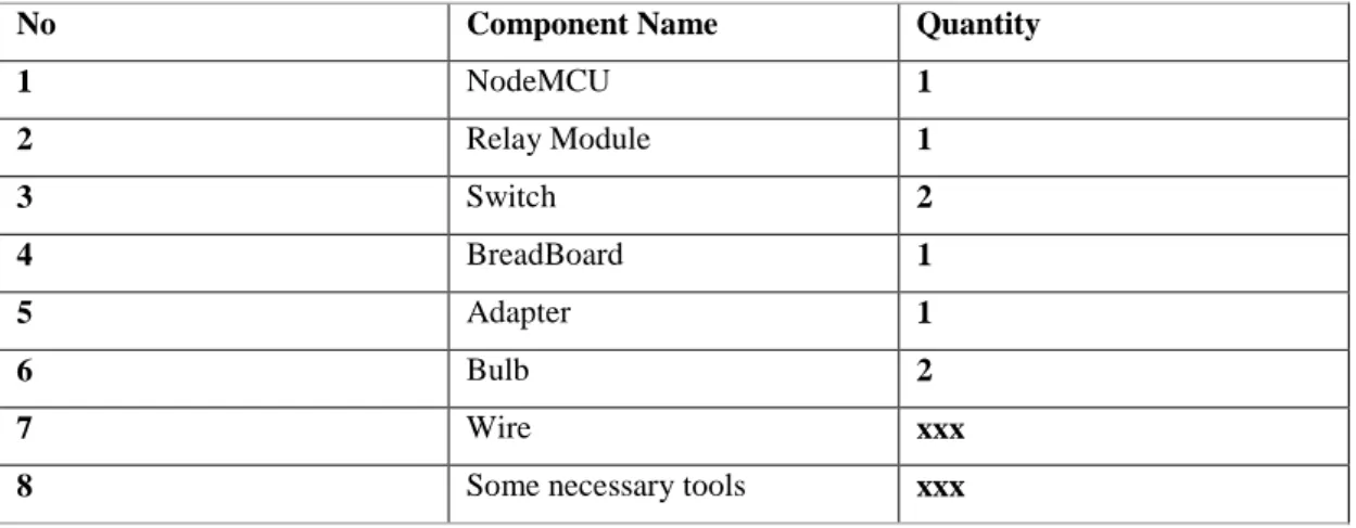
©Daffodil International University 8 3.5 List of Components used in Circuit
This section we will shows our initial project hardware for clearing the internal devices which we assembled.
Table 3.1 list of the component we used
No Component Name Quantity
1 NodeMCU 1
2 Relay Module 1
3 Switch 2
4 BreadBoard 1
5 Adapter 1
6 Bulb 2
7 Wire xxx
8 Some necessary tools xxx
©Daffodil International University 9
CHAPTER 4 Hardware Specification
4.1 Introduction
There are a lot of researches and surveys regarding smart home automation system.
Various researchers have published their projects on home automation system.
Specially they have focused on the comfortness and easiness of the users. There are also some projects on home automation which is made for disabled people. The goal of this project is to ensure the safety, comfortness, and quick-system of savings electricity at home or at any place. The proposed system is designed to monitor the presence of the user as well as the level of leakage gas. The sensor system controls the device through microcontroller.
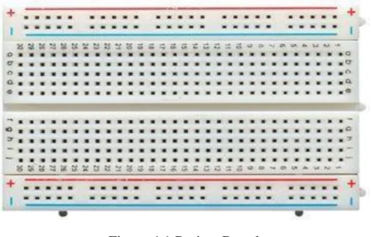
4.2 Bread Board:
Figure 4.1 Project Board
A breadboard is a lacking patch gadget. It is utilized to model gadgets. The leads or terminals of most electronic parts in electronic circuits can be embedded into the openings to associate them. Metal strips interface the breadboard to the remainder of the circuit. The top and base columns of openings are evenly joined and parted in the center. Solderless breadboards interface pin to stick by metal strips inside the breadboard. The format of an ordinary solderless breadboard is made up from two sorts of regions, which are called strips. Strips comprise of interconnected electrical terminals.
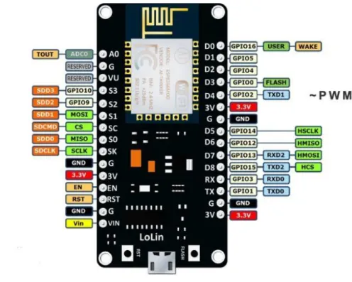
©Daffodil International University 10 4.3 NodeMCU:
Figure 4.2 NodeMCU
NodeMCU is a minimal expense open-source IoT stage. For NodeMCU, open source model board plans are accessible. The two terms "node" and "MCU" are joined to frame
"NodeMCU" (miniature regulator unit). The term "NodeMCU" refers to the firmware rather than the accompanying development kits. NodeMCU has 128 KB RAM and 4MB of Flash memory to store information and projects. Its high-processing power with in-assembled Wi-Fi/Bluetooth and Deep Sleep Operating highlights make it ideal for IoT projects.
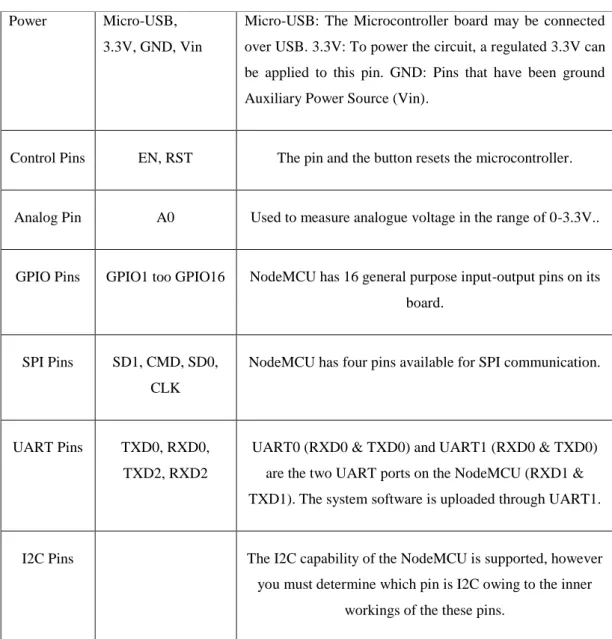
©Daffodil International University 11 4.4 Pinout Configuration:
Table 4.1: Pin Configuration of NodeMCU Power Micro-USB,
3.3V, GND, Vin
Micro-USB: The Microcontroller board may be connected over USB. 3.3V: To power the circuit, a regulated 3.3V can be applied to this pin. GND: Pins that have been ground Auxiliary Power Source (Vin).
Control Pins EN, RST The pin and the button resets the microcontroller.
Analog Pin A0 Used to measure analogue voltage in the range of 0-3.3V..
GPIO Pins GPIO1 too GPIO16 NodeMCU has 16 general purpose input-output pins on its board.
SPI Pins SD1, CMD, SD0, CLK
NodeMCU has four pins available for SPI communication.
UART Pins TXD0, RXD0, TXD2, RXD2
UART0 (RXD0 & TXD0) and UART1 (RXD0 & TXD0) are the two UART ports on the NodeMCU (RXD1 &
TXD1). The system software is uploaded through UART1.
I2C Pins The I2C capability of the NodeMCU is supported, however you must determine which pin is I2C owing to the inner
workings of the these pins.
©Daffodil International University 12 4.5 Relay Module:
Figure 4.3 Relay Module
A power relay module is an electrical switch that is directed by an electromagnet. The electromagnet is activated by a different low-power signal from a miniature regulator.
At the point when it is activated, the electromagnet pulls either to open or close an electrical circuit.
4.6 Wire:
Figure 4.4 Jumper Wire
A jumper wire is an electric wire by which remote electric circuits used for printed circuit boards are linked. By connecting a jumper wire on the circuit, it can be short- circuited and short-cut (jump) to the electric circuit.
Figure 4.5 Wire
©Daffodil International University 13 Electrical wires direct by offering a path of low obstruction to the flow of current through them. When an electric wire is attached to a power source, there is created a movement or flow of electric charge or electrons in the wire.
4.7 Bulb:
Figure 4.6 Bulb
An incandescent bulb is operated on the rule of incandescence, a normal term which means "light produced by heat". In an incandescent type of bulb, an electric current is acrossed through a thin metal filament. The filament is applied warmth until it glows and starts to create light.
4.8 Software Components:
1. Arduino IDE 2. BLYNK APP 4.8.1 Arduino IDE:
For Windows, macOS, and Linux, the Arduino Integrated Development Environment (IDE) is written in C and C++ functions. It is likewise a cross-stage application. It's utilized to compose and transfer projects to Arduino-compatible boards.
This product is utilized to make programs and transfer them to the NodeMCU Wi-Fi module. We can create and transfer projects to the NodeMCU in light of the fact that it is an Arduino compatible board. Sketches are programs made with Arduino programming. These drawings are made in a word processor. It is additionally accessible cutting, sticking and looking likewise for supplanting text. This segment shows blames and gives criticism while putting away and trading. The Arduino
©Daffodil International University 14 Software (IDE) text to the control center, which incorporates every one of the subtleties and blunders. The arranged board and sequential port likewise shown on the windows corner. transfer programs, create, open, and save draws, and open the chronic screen utilizing the toolbar fastens projects will be all approved. Confirm runs a beware of your code to check whether there are any mix-ups prior to gathering it. At the point when it's finished then transfer all of your code to the arranged board when it has been compiled.
Figure 4.7 Arduino IDE GUI
This software is utilized to program the NodeMCU Wi-Fi module and upload the program. We can create and upload projects to the NodeMCU in light of the fact that it is an Arduino-viable board. Portrays are programs that are made with the Arduino Software (IDE). Those portrayals are made in a content tool and put away as a document. Sticking and supplanting text is conceivable with this manager. While putting away, sending out, or showing botches, the message segment gives input. The Arduino Software (IDE) yields text to the control center, which incorporates all blunder alerts and data. The designed board and sequential port are displayed in the base right corner of the window. The toolbar buttons, then again, permit you to approve and transfer programs, produce, open, and save draws, and send off the chronic screen, in
©Daffodil International University 15 addition to other things. At last, building the code, it is checked for faults or error. Then it uploads the code that has been compiled.
4.8.2BLYNK:
Blynk was planned considering IoT. It can remotely oversee gadgets, show sensor information, save and picture information, and direct a few different capabilities. Three fundamental parts make up the stage:
❖ Blynk App - by blending our gadgets, you might make alluring points of interaction for your projects.
❖ Blynk - This server is accountable for all interchanges among cell phones and equipment. We can use Blynk Cloud or work our own Blynk-Its server locally. It's free and open-source, and it might in fact work on a Raspberry Pi.
❖ Blynk-Libraries associate with the server and execute all incoming and outgoing commands on all famous hardware platforms.
Figure 4.8 Blynk App GUI
©Daffodil International University 16 4.9 Summary:
This IoT project is made in a low cost which assures both savings and safety. The device confirms the comfortness of the user as he/she can control the electrical machines by his/her mobile phone with the help of internet from any place. This will be very helpful for sick people they can easily control the light, fan etc without any movement. Overall, this automation system can be viewed as a smart system for home or any place. It can save electricity and it can safe our money. It can be very helpful for our economy also.
©Daffodil International University 17
CHAPTER 5 Working Procedure
5.1 Overview:
The smart system is operated manually and or autonomous to control the system or monitor the device by gathering various information. There are several things related to working procedures. They are….
5.2 Automatic Control:
The D6 pin of Relay NodeMCU is connected with D7 pin. Microcontroller controls the relay through these two pins. And by controlling the relay the bulb is controlled. This process can be completed by internet without any physical presence.
The command which is given by Blynk app, microcontroller completes the task of turning on or off the relay on the basis of that command.
5.3 Manual Control:
For manually control along the automation control, we have connected a switch by which we can control the device very easily whenever we want.
5.4 Communication:
The device is connected to a mobile phone by Wi-Fi. The commands which are sent from that phone, are received as signal to the device through internet. Depending on that signal, the relay is turned on or off or other devices are controlled. Through internet, we can control this device from any corner of the world.
©Daffodil International University 18
CHAPTER 6 Result and Application
6.1 Result:
This is our project final outcome. In this picture we show how it looks like.
Figure 6.1 Project Picture
Here we have used two lights as sample, which are connected with two holders. There are two switches to control the lights. There is a microcontroller Node MCU, a relay module, a bread board. Everything is connected with a jumper wire.
©Daffodil International University 19 Here we give some screenshot of our system UI.
Figure 6.2 Blynk Web LayOut
Figure 6.3 Blynk App LayOut
©Daffodil International University 20 6.2 Application:
This automation system can be best used at home. In addition, the system can be used at office and any institutional apartments also.
6.3Advantages:
1) Less equipment included:
The new system utilizes less equipment and is more energy-productive.
2) Cost Efficient:
The proposed system is more affordable to carry out than the current system. This guarantee depends on the way that the proposed system doesn't need heavy and expensive hardware.
3) Power utilization:
For a long-term operational system, power productivity is vital. Most of remote sensor nodes are powered by 5V adapter, which requires productive power the executives for information perusing from sensors. Sensor systems have an exceptionally high power utilization for the executed systems, which can be brought down by using the proposed systems
6.4 Disadvantages:
Without the access of internet, the device cannot be control from all places by mobile phone. If the internet is turned off and we want to control the device manually, we have to reset the device again and then connect with the internet.
©Daffodil International University 21
CHAPTER 7
Future Work and Conclusion
7.1 Future Work:
We can control everything through automation system. We can assure the safety our home and institutes by automation system. To prevent stealing cars or other machines, the alert system can be used. By measuring the distance of a car, we can use an alarm system to keep a safe distance. Whenever the safety distance will be crossed, the alarm will start ringing. For physically disabled people, such as blinds or deafs, automation system can bring a significance change in their safety and easiness. Thus, the automation system can bring a change in future.
To control this device, we want to develop our own app. By which the we can take one step ahead our country towards technological development by using the our own technology.
7.2 Limitation:
• Unability to use the device in absence of internet.
• Can-not be controlled smartly when internet is gone.
• User has to reset the full system after the device is manually controlled during the absence of internet.
7.3 Conclusion:
This automation system plays an important role for the safety and comfortness of the user. The device is made in a low cost but containing a lot of advantages. For easy controlling the electrical machines, saving the electricity and assuring the safety also.
In this era, people can do and control anything through the use of internet and technology. This project is an output of the blending of internet and technology which contains a remarkable amounts of merits for users.
©Daffodil International University 22
References
1. Asadullah, M., & Ullah, K. (2017, April). Smart home automation system using Bluetooth technology. In 2017 International Conference on Innovations in Electrical Engineering and Computational Technologies (ICIEECT) (pp. 1-6). IEEE.
2. Sági, M., Mijic, D., Milinkov, D., & Bogovac, B. (2012, November). Smart home automation.
In 2012 20th Telecommunications Forum (TELFOR) (pp. 1512-1515). IEEE.
3. Al-Kuwari, M., Ramadan, A., Ismael, Y., Al-Sughair, L., Gastli, A., & Benammar, M. (2018, April). Smart-home automation using IoT-based sensing and monitoring platform. In 2018 IEEE 12th International Conference on Compatibility, Power Electronics and Power Engineering (CPE-POWERENG 2018) (pp. 1-6). IEEE.
4. Wickramasinghe, M. G. D., & Abhayasinghe, N. (2013). LP Gas Leakage Alarm. In SAITM Research Symposium on Engineering Advancements (pp. 32-36).
5. Pavithra, D., & Balakrishnan, R. (2015, April). IoT based monitoring and control system for home automation. In 2015 global conference on communication technologies (GCCT) (pp. 169- 173). IEEE.
6. Murthy, K. S., Herur, P., Adithya, B. R., & Lokesh, H. (2018, July). Iot-based light intensity controller. In 2018 International Conference on Inventive Research in Computing Applications (ICIRCA) (pp. 455-460). IEEE.
7. Stolojescu-Crisan, C., Crisan, C., & Butunoi, B. P. (2021). An IoT-based smart home automation system. Sensors, 21(11), 3784.
8. González-Amarillo, C. A., Cárdenas-García, C. L., Caicedo-Muñoz, J. A., & Mendoza-Moreno, M. A. (2020). Smart Lumini: A Smart Lighting System for Academic Environments Using IOT- Based Open-Source Hardware. Revista Facultad de Ingeniería, 29(54).
9. Findawati, Y., Idris, A., Rachmawati, Y., & Suprayitno, E. A. (2020, June). IoT-Based Smart Home Controller Using NodeMCU Lua V3 Microcontroller and Telegram Chat Application.
In IOP Conference Series: Materials Science and Engineering (Vol. 874, No. 1, p. 012009).
IOP Publishing.
10. Parab, R., & Prajapati, S. (2019). IoT based relay operation. International Journal of Engineering and Advanced Technology, 9(1), 6515-6520.
11. Dhobi, P. A., & Tevar, N. (2017, July). IoT based home appliances control. In 2017 International Conference on Computing Methodologies and Communication (ICCMC) (pp.
648-651). IEEE.
©Daffodil International University 23