AN ALTERNATIVE APPROACH TO DRIVERLESS VEHICLES BY
IMRAN ZAHAN SAJIB 172-15-1584
MD. ZOBYAER SHEIKH 172-15-9699
This Report Presented in Partial Fulfillment of the Requirements for the Degree of Bachelor of Science in Computer Science and Engineering.
Supervised By MS. TANIA KHATUN
Senior Lecturer Department of CSE
Daffodil International University Co-Supervised By
TAJIM MD. NIAMAT ULLAH AKHUND Lecturer
Department of CSE
Daffodil International University
DAFFODIL INTERNATIONAL UNIVERSITY DHAKA, BANGLADESH
SPRING 2021
APPROVAL
This Project titled “An Alternative Approach to Driverless Vehicles”, submitted by Imran Zahan Sajiband Md. Zobyaer Sheikhto the Department of Computer Science and Engineering, Daffodil International University, has been accepted as satisfactory for the partial fulfillment of the requirements for the degree of B.Sc. in Computer Science and Engineering and approved as to its style and contents. The presentation has been held onMay
BOARD OF EXAMINERS
(Name) Chairman
Designation
Department of CSE
Faculty of Science & Information Technology Daffodil International University
(Name) Internal Examiner
Designation
Department of CSE
Faculty of Science & Information Technology Daffodil International University
(Name) External Examiner
Designation
Department of ---
DECLARATION
We hereby declare that, this project has been done by us under the supervision of Ms. Tania Khatun, Senior Lecturer, Department of CSE Daffodil International University. We also declare that neither this project nor any part of this project has been submitted elsewhere for award of any degree or diploma.
Supervised by:
Ms. Tania Khatun Senior Lecturer Department of CSE
Daffodil International University Co-Supervised by:
Tajim Md. Niamat Ullah Akhund Lecturer
Department of CSE
Daffodil International University
Submitted by:
Imran Zahan Sajib ID: 172-15-1584 Department of CSE
Daffodil International University
Md. Zobyaer Sheikh
ID: 172-15-9699 Department of CSE
Daffodil International University
ACKNOWLEDGEMENT
First we express our heartiest thanks and gratefulness to almighty Allah for His divine blessing makes it possible for us to complete the final year project/internship successfully.
We are really grateful and wish our profound indebtedness to Ms. Tania Khatun, Senior Lecturer,Department of CSE Daffodil International University, Dhaka deep Knowledge & keen interest of our supervisor in the field of “IoT’ to carry out this project. Her endless patience, scholarly guidance, continual encouragement, constant and energetic supervision, constructive criticism, valuable advice, reading many inferior drafts and correcting them at all stages have made it possible to complete this project.
We would like to express our heartiest gratitude to the Head, Department of CSE, for his kind help to finish our project and also to other faculty members and the staff of CSE department of Daffodil International University.
ABSTRACT
For over hundreds of years cars have remained the same. Nothing significant has changed. But now, we are seeing a transition from mainstream gasoline powered cars to electric cars.
Undoubtedly, electric cars are the future. And they come in with a wide variety of features. The key thing that electric cars offer unlike their mainstream counterparts is autonomous driving capability. But implementing such a feat requires a huge infrastructure, large scale integration, well maintained roads and many more. In this report, we are going to be developing a remotely guided system for vehicles named Telepilot Action Request System or T.A.R.S in short. This system will be both driver controlled and driverless. The user will be able to drive the vehicle from within and also be able to navigate the vehicle to a location without colliding with moving and non moving objects on the road from a distance using smart devices and a dedicated controller. The system will have built-in GPS as well as obstacle detection sensors. The Doppler radar sensor is used to detect the obstacles on the road. Unlike autopilot, this system can be used to drive vehicles on the off roads as well. This system will have Bluetooth connectivity through which the GPS module data can be accessed. With further developments, this system will be able to assist drivers in avoiding obstacles and minimizing vehicles collisions on the road.
TABLE OF CONTENTS
CONTENTS PAGE
Board of examiners i
Declaration ii
Acknowledgements iii
Abstract iv
CHAPTERS
CHAPTER 1: INTRODUCTION
1-21.1 Introduction 1
1.2 Motivation 1
1.3 Objective 1
1.4 Expected Outcome 2
CHAPTER 2: BACKGROUND
3-42.1 Introduction 3
2.2 Related Works 3
2.3 Research Summary 4
2.4 Challenges 4
3.1.4 Building the remote navigation algorithm 14-16
3.1.5 GPS tracking 17
3.1.6 Programming the system and mounting components 17-18
3.2 Implementation Requirements 18
CHAPTER 4: RESULT AND DISCUSSION
194.1 Introduction 19
4.2 Recommendations 19
CHAPTER 5: CONCLUSION
205.1 Introduction 20
5.2 Summary 20
REFERENCES
21-22LIST OF FIGURES
FIGURES PAGE NO
Figure 3.1.1.a: Components Mounted on the Test Stand 5
Figure 3.1.1.b: Block Diagram of T.A.R.S 6
Figure 3.1.2.a: Arduino Mega 2560 7
Figure 3.1.2.b: Arduino Uno 7
Figure 3.1.2.c: L298N Motor Driver Module 8
Figure 3.1.2.d: Ublox NEO-6M GPS Module 8
Figure 3.1.2.e: HB100X Doppler Radar Sensor 9
Figure 3.1.2.f: HC-05 Bluetooth Module 9
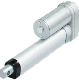
Figure 3.1.2.g: Linear Actuator 10
Figure 3.1.2.h: Sliding Potentiometer 10
Figure 3.1.2.i: High Torque DC Motor 11
Figure 3.1.2.j: Generic Gamepad with Receiver 12
Figure 3.1.2.k: Lithium-ion Batteries 12
Figure 3.1.2.l: TP4056 Charger Module 13
Figure 3.1.3: Flowchart of the collision avoidance algorithm 14 Figure 3.1.4: Flowchart for the remote navigation algorithm 16
Figure 3.1.6: Design of the test stand 17
CHAPTER 1 Introduction
1.1 IntroductionThe largest electric vehicle (EV) manufacturer in the world right now is Tesla. They have sold almost 500,000 in the year 2020 globally. That is equivalent to 29% global market share. But this is nowhere close to the mainstream gasoline powered vehicles. In 2020, Volkswagen sold 9,305,400 units globally which is equivalent to 11.6% global market share. It is clear that the transition to electric cars that we are seeing will take a long time to fully replace the mainstream.
The cars that we see on roads in our country are mostly reconditioned and imported from Japan and the biggest supplier for the cars is Toyota. And the cars are all gasoline powered. Moreover, the cost of any vehicle in our country is expensive, not to mention the import tax for vehicles.
People have to buy a reconditioned car at the price of a premium compared to the rest of the world. Electric cars are not coming to our country any time soon. There needs to be infrastructure, regulations and other all sorts of things for it happen.
Now like the market share of electric vehicles, the autonomous driving capability is far from perfect. The technology is at its infancy. So, an alternative approach for solution for the aforementioned issues would be to integrate remotely driving capability to our vehicles using recent technologies that are developed for the auto industry.
1.2 Motivation
Past two decades have been a crucial time for the revolution for different technologies from mobile phones to cellular networks. With the rapid growth of the internet, things have never been this convenient and time efficient. And this has led us to some interesting fields of engineering like IoT and Robotics have come together to create IoRT which stands for the Internet of Robotics Things which was not possible before. Witnessing the change in the automotive industry we set our goals to enhance vehicle controllability and increase safety through the combination of embedded systems, IoT and robotics.
1.3 Objective
● To develop a robotic system that allows vehicles to be driven remotely and provides driving assist for safety through automation.
● To ensure safer and better driving experience.
1.4 Expected Outcome
● A robotic system that will enable the user to drive a vehicle remotely and also provide assistance in driving for safety and better driving experience enhancing controllability through automation.
CHAPTER 2 Background
2.1 IntroductionAutopilot is a system which is used to control an aircraft, marine craft or spacecraft without requiring any continuous input from any operator. In case of land based vehicles the overall aspect remains the same. And with the spread of autopilot technology the fully driverless vehicles will start to roll out.
Our approach to driverless vehicles is different from Tesla’s advanced driver assistance system.
The system that we are going to develop is a system that will enable an operator to control a specified vehicle from a remote distance through the means of different wireless communication technologies. These types of remotely controlled systems are seen mostly in drones, construction equipment, heavy utility vehicles etc. Typically, this type of system consists of a transmitter and receiver. The downside for such a receiver and transmitter is the range of communication between them. The transmitter has to communicate with the receiver in order to correctly execute the commands given by the operator as inputs. With the satellite communication in place that issue is no longer a fact. But that sort of form of communication is expensive. On the other, land based gasoline powered vehicles use mechanical input systems only. It means that the driver has give input mechanically in order to navigate the vehicle. There is no other way unlike electric vehicles. Because the entire electric vehicle can be driven using a software based control system.
There is a computer that handles all the inputs from the driver. With the introduction of T.A.R.S even some physical handicap people will be able to drive on their own. Moreover, the driver will have driving assistance through smart collision detection and avoidance and automated braking.
2.2 Related Works
Big companies like Volkswagen, General Motors, Audi, Volvo, Ford and Mercedes to name a few are working on their own driverless technologies. Tesla has already completed 1 million mile self driving using their advanced driver assistance system. Google has a similar project called Waymo which uses driverless technology. Recently Apple has announced that it’s going to bring out an electric car with self driving capability within a few years from now.
On the other hand, tech enthusiasts and independent builders are seen to work on systems that allow land based gasoline powered vehicles to be controlled remotely but with a different approach.
2.3 Research Summary
In this study we will be showing a different approach to driverless vehicles using remote driving capability. Also we will design and develop the system required for such technology and make a prototype to demonstrate how it works. We will analyze our results and findings to find out how reliable the system is.
2.4 Challenges
● Needs to be designed from scratch
● Unavailability of components of required parameters
● Requires hands-on experience in multiple fields of engineering i.e. mechanical, electrical, embedded systems etc.
CHAPTER 3 Methodology
3.1 IntroductionThe entire study consists of the following parts as listed below:
a) Designing the test stand
b) Selecting the appropriate components c) Building the collision avoidance algorithm d) Building the remote navigation algorithm e) GPS tracking
f) Programming the system and mounting components 3.1.1 Designing the test stand
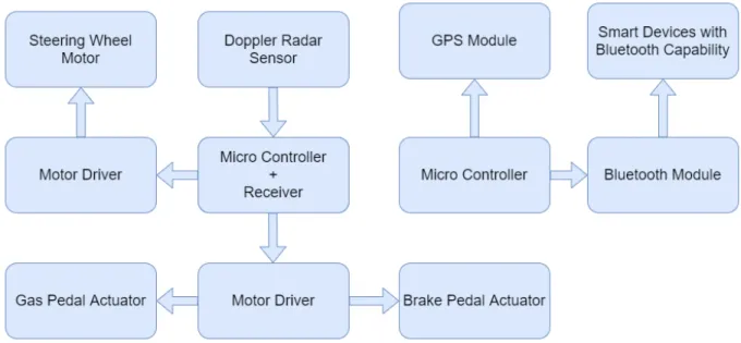
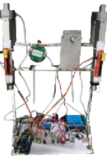
To demonstrate the developed algorithms and how the system behaves, we need to design a test stand where all the components will be mounted and tested for trials and errors to make the system more robust. To move a car we need to replicate the force exerted by the driver on the gas and brake pedal as well as the turning motion of the steering wheel. Linear actuators will be used for exerting force on the pedals. And a high torque DC motor will be used for turning the steering wheel. The actuators and the DC motor will be controlled using motor controllers. The motor controller must be operated using a microcontroller. The microcontroller will get data from the operator through a dedicated receiver as well as from Doppler radar sensor and GPS module and feed signal to the motor controller according to the developed algorithm and the actuators and DC motor will be driven accordingly.
Figure 3.1.1.a: Components Mounted on the Test Stand
Figure 3.1.1.b: Block Diagram of T.A.R.S
e) Doppler Radar Sensor f) HC-05 Bluetooth Module g) Linear Actuator
h) Sliding Potentiometer i) High Torque DC Motor
j) Dual Shock Gamepad with receiver k) Lithium-ion Batteries
l) TP4056 Charger Module
a. Arduino Mega 2560 Microcontroller
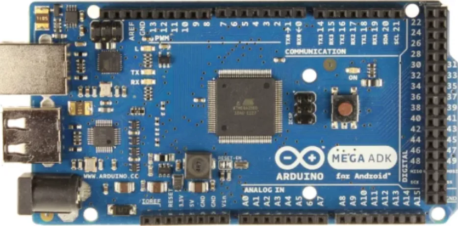
Arduino mega 2560 has been used as the main micro controller for the system. It gets signals from the dual shock gamepad through the receiver and processes the signal according to the given algorithm and gives signals to the motor controller to drive the actuators and motor.
Figure 3.1.2.a: Arduino Mega 2560
b. Arduino Uno
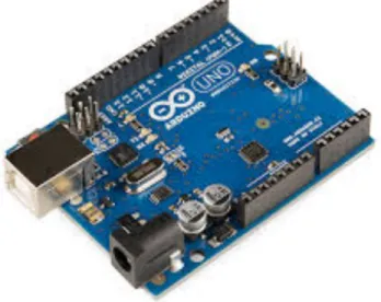
Arduino Uno has been used as the secondary micro controller for the system. It handles GPS tracking for the vehicle. It is coupled with a Bluetooth module for smart device connectivity.
Figure 3.1.2.b: Arduino Uno
c. L298N Motor Controller
L298N motor driver module has been used for controlling the actuators and motor. The module has the L298N IC on board which has 15 pins and can generate a power output of 25W. The driver IC can run up to 2 motors in both clockwise and anti-clockwise.
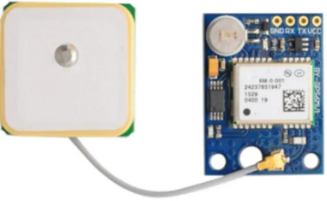
d. GPS Module
Ublox NEO-6M GPS module has been used for GPS tracking as it is cost effective and more popular among hobbyists. It can track up to 22 satellites in orbit on 50 channels and can give a horizontal accuracy of 2.5m. It is extremely power efficient as it has a power save mode.
Figure 3.1.2.d: Ublox NEO-6M GPS Module
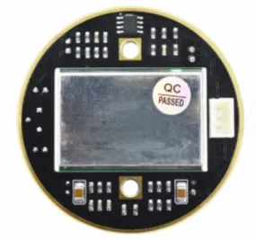
e. Doppler Radar Sensor
HB100X has been used as the moving object detection sensor. It utilizes a method known as Doppler Effect using low level radio waves. The sensor works based on the Doppler Effect. Doppler Effect is the change in frequency of a wave in relation to the observer who is moving relative to the source of the wave. It operates on a frequency of 10.525 GHz. It can also measure the speed of the approaching object. It also works in fog and smoke.
Figure 3.1.2.e: HB100X Doppler Radar Sensor
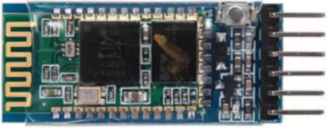
f. HC-05 Bluetooth Module
HC-05 Bluetooth module has been used for letting the operator connect to the system and access the data from the GPS module using any smart device that has Bluetooth capability.
Figure 3.1.2.f: HC-05 Bluetooth Module
Figure 3.1.2.g: Linear Actuator
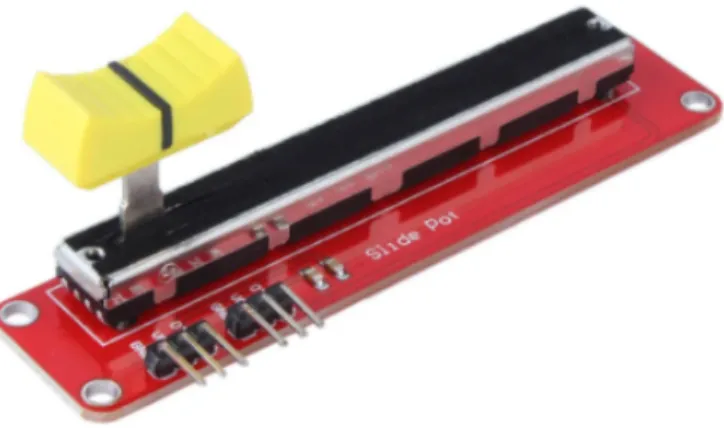
h. Sliding Potentiometer
Not all linear actuators provide position feedback. Position feedback is necessary to determine the position of the extension tube of the actuator. For that sliding potentiometer has been used. Sliding potentiometer is a three-terminal resistor which has a sliding contact used to measure electromotive force.
Figure 3.1.2.h: Sliding Potentiometer
i. High Torque DC Motor
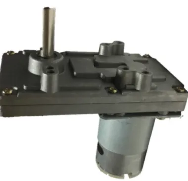
A high torque DC motor has been used to replicate the turning movement of the steering wheel by the driver. The motor uses a reduction gear ratio of 91:1 to increase its torque.
Figure 3.1.2.i: High Torque DC Motor
j. Dual Shock Gamepad with Receiver
A gamepad has been used for sending the input signals from the operator to the microcontroller. The gamepad has a dedicated receiver which works in both serial and USB modes. The gamepad also features 2 analog joysticks, 4 trigger buttons, 4 force sensitive buttons and 4 on/off buttons.
Figure 3.1.2.j: Generic Gamepad with Receiver
k. Lithium-ion Batteries
For powering all the components eight 18650 and two 14500 rechargeable lithium-ion batteries have been used in a configuration of both series and parallel.
Figure 3.1.2.k: Lithium-ion Batteries
l. TP4056 Charger Module
In order to recharge the batteries, TP4056 charger module has been used. It is a 5V charger and can charge two lithium-ion batteries simultaneously.
Figure 3.1.2.l: TP4056 Charger Module
3.1.3 Building the collision avoidance algorithm
This collision avoiding algorithm depends on the data received from the Doppler radar sensor and from the operator. There is one Doppler radar sensor on board which detects moving objects and measures the speed of the object.
Based on the received data the algorithm is divided into two parts.
a) Keeping a safe distance from the front object b) Automatic braking
a. Keeping a safe distance from the front object
If the sensor detects any object in front of it then it will measure the speed of the object relative to the speed of the vehicle. A threshold value is set which is considered safe and if the speed of the object is equal to speed of the vehicle then the system will reduce the vehicle speed by disengaging the gas pedal actuator.
b. Automatic braking
If the object speed is less than the threshold value then the system will brake and make
c) Calculating object speed d) Maintaining safe distance e) Automatic braking
Figure 3.1.3: Flowchart of the collision avoidance algorithm
3.1.4 Building the remote navigation algorithm
For the remote navigation, the system takes command as input from the operator through the receiver and then sends the received signal to the microcontroller. The micro controller processes the signal and sends it to the motor drivers and the motor drivers in turn drive the actuators and motor accordingly. If there is any obstacle detected then the command from the operator is skipped.
Action Description for the Flowchart
a) Reading receiving data b) Processing received data c) Detecting moving object d) Moving forward
e) Braking f) Steering left g) Steering right
Figure 3.1.4: Flowchart for the remote navigation algorithm
3.1.5 GPS Tracking
GPS module is coupled with arduino uno for GPS tracking. This is totally independent of the rest of the system. The data from the GPS module can be accessed through any smart device with Bluetooth capability. And for the Bluetooth connectivity HC-05 has been used. Using the GPS module longitude, latitude, data, time, altitude etc can be obtained. The module can receive data from 22 satellites in orbit and find the location with pin point accuracy.
3.1.6 Programming the system and mounting components
A test stand has been designed for mounting the components. All the mounted components can be unmounted from the stand easily. The stand is sturdy enough to withstand the vibration from the mechanical parts. It is well insulated as well.
All the programming has been done on Arduino IDE.
3.2 Implementation Requirements
For the implementation of this project, we have used the following.
● Arduino IDE
● C/C++ programming language
● Bluetooth Terminal
● Windows
CHAPTER 4
RESULTS AND DISCUSSION
4.1 Introduction
In general, the system has performed well. It could receive commands from the operator as inputs successfully. It also could detect objects in front of it and calculate the relative speed of the object. The actuators and the steering motor worked smoothly. The GPS module was accurate and could receive data from the satellite quite reliably. The algorithms worked well too.
But in this configuration, the system cannot be used to drive the vehicle in both directions i.e.
forward and backward. It can control the vehicle in the direction the operator puts in beforehand.
Additional actuator is needed. The system cannot also detect approaching objects from behind or from the sides of the vehicle. It needs multiple sensors placed at different positions. The battery backup was not satisfactory as the drain was high. The number of cells needs to be increased. All the battery is rechargeable and charging time for each battery was 3-4 hours.
4.2 Recommendations
The system we have developed requires further development that will make it more reliable and robust. A desktop application can be developed to monitor the overall status of the system real time. The system can be enhanced to store data to the server so that the desktop application can access it. Cameras can be installed for video feed. Now two micro controllers are used and both of them are independent of each other. Later, they can be programmed to communicate with each other for better collision detect and avoidance. The system can be made to handle from remote ignition of the vehicle to controlling the head and back lights and many more.
CHAPTER 5 CONCLUSION
5.1 IntroductionDriverless vehicle technology is a technology that almost all the vehicle manufacturing companies are trying to develop. They have state of the art technologies and testing facilities.
This technology requires accuracy as it is directly involved with human lives. With the high level of accuracy, the probability of accidents becomes minimal.
This system can be applied to vehicles as a telepilot system where the safety of the people involved is of big concern for example in fire fighting trucks, construction and equipment handling vehicles, military convoy and artillery carrying vehicles, garbage trucks, hazardous cargo carrying vehicles etc. And as the technology develops it can be integrated to mainstream passenger vehicles. Handicapped people will be able to drive on their own easily as the system assists the driver and the vehicle can be controlled using a dedicated controller..
In the proposed system, collision avoidance algorithm is solely dependent on the Doppler radar sensor. To increase the reliability multiple sensors are needed with failsafe measures. The operator cannot see what’s happening inside the vehicle while driving from outside the vehicle.
Integrated cameras can resolve that issue by adding different perspectives.
5.2 Summary
In this study, we have tried to develop a robotic system that will enable the user to drive a vehicle remotely and also provide assistance in driving for safety and better driving experience enhancing controllability through automation with an alternative approach to driverless vehicles.
In order to accomplish our objectives, we developed and implemented collision avoidance and remote navigation algorithms.
In this project, we have made a prototype demonstrating the possibility of developing the aforementioned system that can be implemented in real life.
REFERENCES
[1] Jang-Ho Cho, Dong-Sung Pae, Myo-Taeg Lim, Tae-Koo Kang, "A Real-Time Obstacle Avoidance Method for Autonomous Vehicles Using an Obstacle-Dependent Gaussian Potential Field", Journal of Advanced
Transportation, vol. 2018, Article ID 5041401, 15 pages, 2018. https://doi.org/10.1155/2018/5041401
[2] William Benn, Stanislao Lauria, "Robot Navigation Control Based on Monocular Images: An Image Processing Algorithm for Obstacle Avoidance Decisions", Mathematical Problems in Engineering, vol. 2012, Article
ID 240476, 14 pages, 2012. https://doi.org/10.1155/2012/240476
[3] Zhao, J., Liang, B. and Chen, Q. (2018), "The key technology toward the self-driving car", International Journal of Intelligent Unmanned Systems, Vol. 6 No. 1, pp. 2-20. https://doi.org/10.1108/IJIUS-08-2017-0008
[4] Sina Nordhoff, Joost de Winter, Miltos Kyriakidis, Bart van Arem, Riender Happee, "Acceptance of Driverless Vehicles: Results from a Large Cross-National Questionnaire Study", Journal of Advanced
Transportation, vol. 2018, Article ID 5382192, 22 pages, 2018. https://doi.org/10.1155/2018/5382192
[5] Ching-Yao Chan, Advancements, prospects, and impacts of automated driving systems, International Journal of Transportation Science and Technology, Volume 6, Issue 3, 2017, Pages 208-216, ISSN 2046-0430,
https://doi.org/10.1016/j.ijtst.2017.07.008. (https://www.sciencedirect.com/science/article/pii/S2046043017300035) [6] Wolfgang Gruel, Joseph M. Stanford, Assessing the Long-term Effects of Autonomous Vehicles: A Speculative Approach, Transportation Research Procedia, Volume 13,2016, Pages 18-29, ISSN 2352-1465,
https://doi.org/10.1016/j.trpro.2016.05.003. (https://www.sciencedirect.com/science/article/pii/S2352146516300035) [7] Hong Yang, Zhenyu Wang, Kun Xie, Impact of connected vehicles on mitigating secondary crash risk,
International Journal of Transportation Science and Technology, Volume 6, Issue 3, 2017, Pages 196-207, ISSN 2046-0430,https://doi.org/10.1016/j.ijtst.2017.07.007.
(https://www.sciencedirect.com/science/article/pii/S2046043017300060)
[10] Q. Li, A.C. Adriaansen, J.T. Udding, A.Y. Pogromsky, Design and Control of Automated Guided Vehicle Systems: A Case Study, IFAC Proceedings Volumes, Volume 44, Issue 1, 2011, Pages 13852-13857, ISSN 1474-6670, ISBN 9783902661937,https://doi.org/10.3182/20110828-6-IT-1002.01232.
(https://www.sciencedirect.com/science/article/pii/S1474667016458507)
[11] R.C. Dixon, Glen Bright, Ronald Harley, Robust Kalman Filter Based Localisation of an Omnidirectional Automated Guided Vehicle, IFAC Proceedings Volumes, Volume 45, Issue 6, 2012, Pages 912-917, ISSN 1474-6670, ISBN 9783902661982,https://doi.org/10.3182/20120523-3-RO-2023.00070.
(https://www.sciencedirect.com/science/article/pii/S1474667016332669)
[12] D. C. R. Ranasinghe, W. K. I. L. Wanniarachch and U. A. D. N. Anuradha, "GPS guided auto sensing system for motor vehicles," 2019 International Research Conference on Smart Computing and Systems Engineering (SCSE), Colombo, Sri Lanka, 2019, pp. 184-189, doi: 10.23919/SCSE.2019.8842715.
[13] Doppler Effect, available at <<https://en.wikipedia.org/wiki/Doppler_effect>>, last accessed on 30 January 2021, at 19:52 (UTC).