SMART OFFICE AUTOMATION SYSTEM
BY
SRIJAN KUMAR GHOSH ID: 142-15-4043 NANDITA BAGCHI
ID: 142-15-3648
SK. ABDULLAH AL ARAFATH ID: 142-15-3707
This Report Presented in Partial Fulfillment of the Requirements for the Degree of Bachelor of Science in Computer Science and Engineering
Supervised By Md. Sadekur Rahman
Assistant Professor Department of CSE
Daffodil International University
DAFFODIL INTERNATIONAL UNIVERSITY
DHAKA, BANGLADESH MAY 2018
©Daffodil International University i
APPROVAL
This Project titled “Smart Office Automation System”, submitted by Srijan Kumar Ghosh, Nandita Bagchi and SK Abdullah Al Arafath to the Department of Computer Science and Engineering, Daffodil International University, has been accepted as satisfactory for the partial fulfillment of the requirements for the degree of Bachelor of Science in Computer Science and Engineering (BSc) and approved as to its style and contents. The presentation has been held on 05 May 2018.
BOARD OF EXAMINERS
Dr. Syed Akhter Hossain Chairman
Professor and Head
Department of Computer Science and Engineering Faculty of Science & Information Technology Daffodil International University
Dr. Sheak Rashed Haider Noori Internal Examiner Associate Professor
Department of Computer Science and Engineering Faculty of Science & Information Technology Daffodil International University
MD. Zahid Hasan Internal Examiner
Assistant Professor
Department of Computer Science and Engineering Faculty of Science & Information Technology Daffodil International University
Dr. Mohammad Shorif Uddin External Examiner Professor
Department of Computer Science and Engineering Jahangirnagar University
©Daffodil International University ii
DECLARATION
We hereby declare that, this project has been done by us under the supervision of Md. Sadekur Rahman, Assistant Professor, Department of CSE Daffodil International University. We also declare that neither this project nor any part of this project has been submitted elsewhere for award of any degree or diploma.
Supervised by:
Md. Sadekur Rahman Assistant Professor Department of CSE
Daffodil International University Submitted by:
Srijan Kumar Ghosh ID: 142-15-4043 Department of CSE
Daffodil International University
Nandita Bagchi ID: 142-15-4043 Department of CSE
Daffodil International University
SK Abdullah Al Arafath ID: 142-15-3707
Department of CSE
Daffodil International University
©Daffodil International University iii
ACKNOWLEDGEMENT
First we express our heartiest thanks and gratefulness to almighty God for His divine blessing makes us possible to complete the final year project successfully.
We really grateful and wish our profound our indebtedness to Md. Sadekur Rahman, Assistant Professor, Department of CSE Daffodil International University, Dhaka. Deep Knowledge & keen interest of our supervisor in the field of “Embedded Systems Circuits and Programming” motivated us to carry out this project. His endless patience ,scholarly guidance ,continual encouragement , constant and energetic supervision, constructive criticism , valuable advice ,reading many inferior draft and correcting them at all stage have made it possible to complete this project.
We would like to express our heartiest gratitude to Prof. Dr. Syed Akhter Hossain and Head, Department of CSE, for his kind help to finish our project and also to other faculty member and the staff of CSE department of Daffodil International University.
We would like to thank our entire course mate in Daffodil International University, who took part in this discuss while completing the course work.
Finally, we must acknowledge with due respect the constant support and patience of our parents.
©Daffodil International University iv
ABSTRACT
Technology is developing at a furious pace. Recent technological development in chip and telecommunications have provided the basis of office automation. Automation plays a very important role in our lives. It makes the work easier and simpler so for a simplified and easy living.
“Smart Office Automation System” is a project that aims to target to facilitate the Smartphone users to control their appliances through their Smartphones by sending a message. An Arduino microcontroller is used in our project to connect all the office appliances to manipulate this system by a mobile app. User can use the mobile app to control their appliances using message.
©Daffodil International University v
CONTENTS
TABLE OF CONTENTS PAGE
Board of examiners i
Declaration i i
Acknowledgements i i i
Abstract i v
CHAPTER
CHAPTER 1: Introduction 01-02
1.1 Overview 01
1.2 Motivation 01
1.3 Objectives 01
1.4 Expected Outcome 02
1.5 Report Layout 02
CHAPTER 2: DESCRIPTION OF HARDWARE PARTS 03-10
2.1 Name of tools and materials 03
2.2 Arduino Uno 03
2.3 Jumper Wires 04
2.4 Types of Jumper Wires 05
2.5 Battery - Lithium polymer battery 05
2.6 USB Cable 06
2.7 Breadboard 07
2.8 Resistor 07
2.9 LED Bulb 08
2.10 LCD (Liquid Crystal Display) 08
2.11 Bluetooth Module HC-05 09
2.12 Motor Driver L293D 09
2.13 Output Device (Fan, Tube Light, LED Bulb) 10
©Daffodil International University vi CHAPTER 3: REQUIRMENTS AND DESIGN SPECIFICATION 11-16
3.1 Introduce to IDE 11
3.2 Business Processing Modeling 11
3.3 Use Case Modeling and Description 12
3.4 MIT app inventor and Android studio 13
3.5 Development Process 14
3.6 GUI for this Project 15
3.6.1 User Interfaces 15
3.6.1 User Interfaces and Search Bluetooth Module 15
3.6.2 Typing Interface and After Sending Message 16
CHAPTER 4: HARDWARE CONNECTIONS 17-24
4.1 Introduction 17
4.2 Initial system module connections 17
4.2.1 Motor Driver Connection 17
4.2.2 Fan Connection 19
4.2.3 Configure Bluetooth Module HC-05 20
4.2.4 Configure LED and mini tube light 20
4.2.5 Configure LCD 21
4.2.6 Circuit diagram of LCD 23
4.3 Upgraded system module connections 24
CHAPTER 5: IMPLEMENTATION AND TESTING 25-29
5.1 Display 25
5.2 Mini Tube Light 25
5.3 Projector and AC 27
5.4 Fan 28
5.5 Final Output 29
©Daffodil International University vii
CHAPTER 6: CONCLUSION AND FUTURE SCOPE 30-30
6.1 Current Limitations 30
6.2 Future Scopes 30
REFERENCES 31
APPENDIX 32
©Daffodil International University viii
LIST OF FIGURES
PAGEFig 2.2: Arduino Uno 4
Fig 2.4: Types of Wires 5
Fig 2.5: Battery - Lithium polymer battery 5
Fig 2.6: USB Cable 6
Fig 2.7: Breadboard 7
Fig 2.8: Resistor 7
Fig 2.9: LED Bulb 8
Fig 2.10: LCD 8
Fig 2.11: Bluetooth Module HC-05 9
Fig 2.12: Motor Deriver L293D 9
Fig 2.13: Light, Fan & LED 10
Fig 3.2: Business Process Modeling 11
Fig 3.3: Use Case Model 12
Fig 3.4: MIT app inventor IDE 13
Fig 3.5: Development Process 14
Fig 3.6.1A: User Interface 15
Fig 3.6.1B: Search Bluetooth Module 15
Fig 3.6.2A: Typing Interface 16
Fig 3.6.2B: After Send Message 16
Fig 4.2.1: Motor Driver 18
Fig 4.2.1: Motor Driver Connection 19
Fig 4.2.2: Fan Connection 20
Fig 4.2.3: Bluetooth Module 20
Fig 4.2.3: Bluetooth Module connection 20
Fig 4.2.4: Mini Tube Light 21
Fig 4.2.5: Pin Diagram in LCD 22
Fig 4.2.6: Circuit Diagram of LCD 23
Fig 4.2.6: LCD Connection 23
Fig 4.3: Completed Connection 24
©Daffodil International University ix
Fig 5.1: LCD Display Output 25
Fig 5.2.1: Brightness High 26
Fig 5.2.2: Brightness Medium 26
Fig 5.2.4: Tube Light Off 26
Fig 5.3.1: Brightness High 27
Fig 5.3.2: Brightness Medium 27
Fig 5.3.3: Brightness Medium 27
Fig 5.4.1: Fan On 28
Fig 5.4.2: Fan Off 28
Fig 5.4.1: Final Output All Appliance OFF 29
Fig 5.4.1: Final Output All Appliance On 29
©Daffodil International University 1
CHAPTER 1 INTRODUCTION 1.1 Overview
Within modern world, people’s life changes day by day with the aid of science. Although People in the advanced country like USA, UNITED KINGDOM, Australia can invest thousands of dollar or euro for automated office system by using some automation company like “One Button”, our project members imagined a complete smart office automation system with a very reasonable low cost.
Moreover people all over the world and even in our very own country uses Smartphone for their daily purposes. We can add a new dimension to this usages list by controlling our office appliance plus much more with the help of smartphone.
1.2 Motivation
The primary object of our project is to provide a communication link between office appliances and Smartphone towards the remote user but with a low cost system. As a result we have chosen Arduino Uno. Because it’s an inexpensive microcontroller with a significant power to control many more device. This is the microcontroller which people uses all around the globe. Therefore, if we can make system with the help of Arduino Uno hen people all over the world will be able to use it with minimum cost.
Every person with either a mobile or computer with an internet connection can imagine an IOT based automated life through our awesome and life-changing product.
As we live in a world where most of the people have smartphone, just imagine a simple home kit running through embedded system could control a person’s every single appliances and multiple appliance.
1.3 Objectives
The main objectives of the project are as follows:-
To develop an app that will provide users to control their appliances via SMS.
©Daffodil International University 2
To use a microcontroller device to connect all the office appliance like Light, Fan, AC, Projector, PC etc.
To enable our system to control the brightness of our project, and LED.
To use Bluetooth module HC-05 for connecting the apps to control the appliances.
1.4 Expected Outcome
We want to control office appliance like Light, Fan, Projector, AC etc. by sending message through our app. In order to control any specific electronics appliances of any room to off, on or to control the brightness of light, we go to our app and we will type room no, appliance name, and action.
Like we want to off a Fan room number 302 then we will type rm302 fan off and we want to control a projector room number 540 then we will type rm540 projector brightness normal, high, and low.
1.5 Report Layout
Chapter 1: In this chapter we have just added a simple overview, motivation, objective, expected outcome of our work. How we are motivated to this project and added the objectives of our project.
Chapter 2: This chapter includes the description about the hardware components like Arduino Uno, rechargeable battery, led bulb and mini tube light, Bluetooth Module HC-05, Motor Driver L293D etc.
Chapter 3: Here we describe about the graphical user interface of our application and how the Bluetooth Module was connected with the Application and working procedure of the application.
Chapter 4: This is the most important chapter, we describe about the connection of our Hardware Components.
Chapter 5: Here we’ve described the working procedure of our project implementation and testing procedure.
Chapter 6: This chapter highlights current limitation and future scope of our project.
©Daffodil International University 3
CHAPTER 2
DESCRIPTION OF HARDWARE PARTS 2.1 Name of tools and materials
Tools and materials used in our project are listed below followed by their description:
1. Arduino Uno
2. Rechargeable Battery
3. Led Bulb and mini tube light 4. Jumper Wires
5. Breadboard 6. USB Cable 7. Resistor 8. LCD
9. Bluetooth Module HC-05 10. Motor Driver L293D
11. Output devices (Light & Fan and others)
2.2 Arduino Uno
Arduino Uno is one kind of single board microcontrollers and open-source electronics platform and it makes easy to communicate between hardware and software.
The Arduino Uno board will be the brain of the robot, as it will be running the software that will control all the other parts. In the Figure-2.1 show the Arduino Uno which product we are used in our project. Arduino Uno is the most popular board and it has many different components. These components are described given below [1].
Power USB: It’s mainly used to supply power from computer to Arduino board. This is supplied by a USB cable.
Voltage Regulator: It controls how much voltage that is let into the Arduino board.
Arduino Reset: Reset Arduino board and start our program right from the beginning.
Pins(5V , 3.3V, GND, Digital, Analog, PWM, AREF):
5V & 3.3V: Supplies 5 and 3.3 Volts of power.
©Daffodil International University 4
GND: 3 GND pin on a Arduino board which are useful to ground our circuit.
Digital: Arduino board has 14 digital pins (0-13). These pins are often used to both digital input and output.
Analog: Arduino board has 6 analog pins (A0-A5). These pins are often used to analog input.
PWM: Some digital pins are used to analog output (3, 5, 6, 9, 10, and 11) that is called PWM pins.
AREF: It’s used for Analog Reference.
Power LED Indicator: when we plug in our Arduino board into a power supply then LED will blinking.
TX and RX: TX- transmit data and RX- receive data from Arduino board.
Main IC: The brain of Arduino board.
Fig 2.2: Arduino Uno [2]
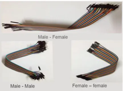
2.3 Jumper Wires
Jumper wires is an electrical wire with a solid tip at each end, which is normally used to interconnect the components in a breadboard. They are used to transfer electrical signals on the breadboard to Arduino board.
©Daffodil International University 5
2.4 Types of Jumper Wires
Variation of jump wires with insulated terminals as per male-female combinations:
Male - Male
Male – Female
Female – female
Fig 2.4: Types of Wires
2.5 Battery - Lithium polymer battery
Lithium polymer battery, rechargeable lithium ion battery technology. Unlike cylinders and primary cells, use flexible packaging, which makes them light but not too sturdy.
©Daffodil International University 6 Fig 2.5: Battery - Lithium polymer battery
2.6 USB Cable
This USB cable is used to upload the program to the Arduino Board. The cable is connected to the computer one at a time, and the other to the Arduino board.
Fig 2.6: USB Cable
©Daffodil International University 7
2.7 Breadboard
Breadboard is a prototype of electronic construction base. We are working with this jumper and led connection. It consists of interconnected electrical terminals.
Fig 2.7: Breadboard [3]
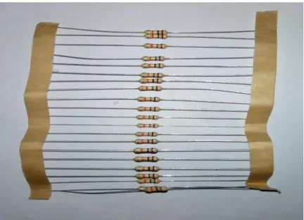
2.8 Resistor
A resistor is a double-ended electrical component that can be used as a passive component to reduce current while reducing the voltage in the circuit.
Fig 2.8: Resistor
©Daffodil International University 8
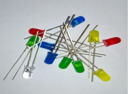
2.9 LED Bulb
LED bulbs use semiconductor devices that emit visible light when current is passed through.
Fig 2.9: LED Bulb
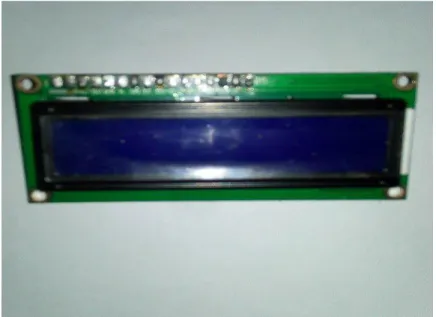
2.10 LCD (Liquid Crystal Display)
A liquid crystal display is a non-light emitting device that produces an images by polarizing light from an internal light source. LCD is mainly used for small systems such as calculators, laptops and computers.
Fig 2.10: LCD
©Daffodil International University 9
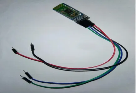
2.11 Bluetooth Module HC-05
HC-05 Bluetooth Module is a wireless device that connected our smartphone via an apps and control our project appliance like as fan, light, AC, projector etc. HC-05 works on serial communication.
Fig 2.11: Bluetooth Module HC-05
2.12 Motor Driver L293D
L293D is an integrated circuit and bi-directional motor deriver. Motor driver stand for an interface between Arduino and the motors. Motor deriver has 16pin- 2Enable, 2VCC, 4Input, 4 Output and 4GND.
Fig 2.12: Motor Deriver L293D [6]
©Daffodil International University 10
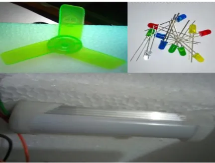
2.13 Output Device (Fan, Tube Light, LED Bulb)
We are using this appliance for our project output, here is some LED bulb, Fan and Mini Tube Light.
Fig 2.13: Light, Fan & LED
©Daffodil International University 11
CHAPTER 3
REQUIRMENTS AND DESIGN SPECIFICATION 3.1 Introduce to IDE
Integrated Development Environment (IDE) is a software application that provides computer programmers with an integrated facility for developing any software. Here for our Smartphone app we have to work on different IDE [8].
3.2 Business Process Modeling
Fig 3.2: Business Process Modeling
In our BPM we use two separate pools for the User control and Admin control. This way, we can clearly define who is in control of which process.
In the Admin control pool, Admin built the interface and stored the interface as command or code.
In the User control pool, User searched and connect the Bluetooth. Type an interface as a message and send the message via Bluetooth. It will check with the built-in command if it is correct command the text color will be blue otherwise it will show red color.
©Daffodil International University 12
3.3 Use Case Modeling and Description
Fig 3.3: Use Case Model Use case Description:
Use case ID: 001
Use case Name: Bluetooth App
Description: This use case allows users to connect their smartphone with Bluetooth module. Users also have to type interface as a message and send. Correct input shown as blue color and wrong input shown as red color.
Primary Actor: User Secondary Actor: Admin Pre-condition:
User have to Search Bluetooth.
User hove to Connect Bluetooth.
Post-condition:
The system display the relevant command with the color.
©Daffodil International University 13 Normal Flow:
Search Bluetooth.
Connect Bluetooth.
Type Interface.
Check Interface.
Display Message.
Alternative Flows:
After searching Bluetooth will be found or not found.
Connection will be Secure, In Secure, Make Discoverable or Setup.
Display Message color Blue or Red.
3.4 MIT app inventor and Android studio
Here for our project, we will use Android Studio and MIT APP Inventor to develop our first Android-based mobile application. We also want to develop it on other platforms such as IOS after completing our project.
Fig 3.4: MIT app inventor IDE
©Daffodil International University 14
3.5 Development Process
App Inventor Interface has two section Designer and Block. Designer Viewer section also known as user interface. User interface has many components like as Button, Check Box, Label, Image, List View, Image, Text Box etc. This component just drag and drop viewer section.
Fig 3.5: Development Process
©Daffodil International University 15
3.6 GUI for this Project
3.6.1 User Interfaces and Search Bluetooth Module
After development our app interface is Fig 3.6.1A here we are keeping search menu option in right side.
Fig 3.6.1A: User Interface
When we are searching, our Bluetooth module hc-05 is showing our app this interface Fig3.6.1B and any other nearest device is showing.
Fig 3.6.1B: Search Bluetooth Module
©Daffodil International University 16
3.6.2 Typing Interface and After Sending Message
Fig 3.6.2A we are showing typing interface of our app. Left side is text area and right side is sending option.
Fig 3.6.2A: Typing Interface
After sending SMS our app interface is Fig 3.6.2B when we are sending any incorrect SMS then our app is showing this SMS red color otherwise our app is showing this SMS blue color.
Fig 3.6.2B: After Send Message
©Daffodil International University 17
CHAPTER 4
HARDWARE CONNECTIONS 4.1 Introduction
In this chapter, we will discuss the hardware connection in our project. Hardware connections is the most important part in our project or any Arduino base project.
We will divided into two parts in our connection of our project:
One is Initial system module connections.
Another is Upgraded system module connections.
4.2 Initial system module connections
Initial system module connections mainly used to testing purpose connections in our project.
4.2.1 Motor Driver Connection
Hardware Required
Arduino Uno
Breadboard
L293D Motor Driver
Jumper Wire
The L293D is a 16 pin IC, and its two side divided by 8pins each side. There are 4 INPUT pins, 4 OUTPUT pins, 4 GND pins, 2 VCC pins and 2 ENABLE pins for each motor [1].
©Daffodil International University 18 Fig 4.2.1: Motor Driver [6].
Pin 1: When Enable1 is high, the left side of the IC is working.
Pin 2: Input 1, when this pin is high, current will flow through output 1.
Pin 3: Output 1, this pin is connected to one end of the motor.
Pin 4/5: GND pin.
Pin 6: Output 2, this pin is connected to one end of the motor.
Pin 7: Input 2, when this pin is high, current will flow through output 2.
Pin 8: VCC1, used to supply power to the connected motor. The maximum voltage is 5V to 36V.
Pin 9: When Enable2 is high, the right half of the IC will work.
Pin 10: Input 4, when this pin is high, current will flow through output 4.
Pin 11: Output 4, this pin is connected to one end of the motor.
Pin 12/13: GND pin.
Pin 14: Output 3, this pin is connected to one end of the motor.
Pin 15: Input 3, when this pin is high, current will flow through output 3.
Pin 16: VCC, used to power the IC, i.e. 5V.
©Daffodil International University 19 Fig 4.2.1: Motor Driver Connection
4.2.2 Fan Connection
Pin 3, 6 and pin 11, 14 motor driver output pin will be connected to motor. Given below we are showing picture in our project of fan connection.
Fig 4.2.2: Fan Connection
©Daffodil International University 20
4.2.3 Configure Bluetooth Module HC-05
Hardware Required
Arduino Uno
Breadboard
Bluetooth Module HC-05
Jumper Wire
Bluetooth Module HC-05 has 4 parts, TX, RX, GND and VCC.
TX pin: Transmit data.
RX pin: Receive data.
GND pin: Ground Connection.
VCC pin: For Power Supply.
Fig 4.2.3: Bluetooth Module [5] Fig 4.2.3: Bluetooth Module connection
4.2.4 Configure LED and mini tube light
Hardware Required
Arduino Uno
Breadboard
©Daffodil International University 21
LED
Jumper Wire
10komh resistor
LED and mini tube light has two part anode and cathode. Anode pin will be connected any digital pins in our Arduino board and cathode pin will be connected GND pins with the resistor. Given below we are showing picture in our project of fan connection.
Fig 4.2.4: Mini Tube Light
4.2.5 Configure LCD
Hardware Required
Arduino Uno
Breadboard
LCD
Jumper Wire
10komh resistor
The LCD module has 16 pins and can be operated in 8bit mode or 4bit mode. We will used in 4bit module in our project. Pin diagram is given below:
©Daffodil International University 22 Fig 4.2.5: Pin Diagram in LCD [4]
The name and functionality of each pin are given below.
Pin1 (VSS): Connected will be GND pin of the LCD.
Pin2 (VCC): Connected will be VCC pin of the LCD module (+5V).
Pin3 (VEE): Contrast adjustment pin.
Pin4 (RS): Register select pin of Arduino board.
Pin5 (R/W): Read/Write modes of Arduino Uno. This pin is used for selecting between read and write modes. A logic high on this pin activates read mode and a logic low on this pin activates write mode.
Pin6 (E): Enable pin of the Arduino board.
Pin7 (DB0) to Pin14 (DB7): Between DB0 to DB7 are data pins.
Pin15 (LED+): Anode of the back light LED.
Pin16 (LED-): Cathode of the back light LED.
©Daffodil International University 23
4.2.6 Circuit diagram of LCD
Fig 4.2.6: Circuit Diagram of LCD [4]
In this project we are using 4bit modes that means only 4 digital input lines of the LCD.
Pin 1, 3 & 16 are connected GND, 2, 15 are connected VCC (+5V), digital pins are connected 2, 11, 12, and 13 pots of the Arduino board, and enable pin is connected 8 no ports. Given below we are showing picture in our project of LCD connection.
Fig 4.2.6: LCD Connection
©Daffodil International University 24
4.3 Upgraded system module connections
At last, we are showing our completed project with Bluetooth module, LCD, Mini tube light, Led, Fan, Motor deriver, Arduino Uno, Breadboard Jumper wire etc.
Fig 4.3: Completed Connection
©Daffodil International University 25
CHAPTER 5
IMPLEMENTATION AND TESTING
In this chapter, we will discuss final output of our Arduino base project Smart Office Automation System. Different type of output in our project is shown below.
5.1 Display
We are using LCD display in our project for showing name of the control room and on, off appliance that are using in our project.
Fig 5.1: LCD Display Output
5.2 Mini Tube Light
We are using mini tube light at room number 3. When we are sending message After Bluetooth module connection between smart phone and Arduino Uno then tube light given our expected output. Given below, we are showing some output picture of our mini tube light output.
©Daffodil International University 26 Fig 5.2.1: Brightness High Fig 5.2.2: Brightness Medium
Fig 5.2.3: Brightness Low Fig 5.2.4: Tube Light Off
When we are sending message “rm3 light on”, the tube light on high brightness Fig 5.2.1, and
“rm3 light normal”, the tube light on medium brightness Fig 5.2.2 and “rm3 light low”, the tube light on low brightness Fig 5.2.3 and “rm3 light off”, the tube light off Fig 5.2.4.
©Daffodil International University 27
5.3 Projector and AC
We are using Projector and AC at room number 5. When we are sending message our expected output given. Given below, we are showing some output picture of Projector or AC output.
Fig 5.3.1: Brightness High Fig 5.3.2: Brightness Medium
Fig 5.3.3: Brightness Medium
When we are sending message “rm5 projector on”, the projector on high brightness Fig 5.3.1, and
“brightness normal”, the projector given standard brightness Fig 5.3.2 and “rm5 projector off”, the projector off Fig 5.2.3
©Daffodil International University 28
5.4 Fan
We are using Fan at room number 4. When we are sending message, our expected output given.
Given below, we are showing some output picture of Fan output.
Fig 5.4.1: Fan On
Fig 5.4.2: Fan Off
When we are sending message “rm4 fan on”, the Fan on Fig 5.4.1, and “rm4 fan off”, the fan off Fig 5.4.2
©Daffodil International University 29
5.5 Final Output
Given below, we are showing some output picture of our project final output.
Fig 5.4.1: Final Output All Appliance OFF
Fig 5.4.1: Final Output All Appliance On
©Daffodil International University 30
CHAPTER 6
CONCLUSION AND FUTURE SCOPE 6.1 Current Limitations
We tried our best to develop our project but having some limitations and obstacles. Here we will discuss some of those limitations which might be solved in future.
Our mobile apps currently support only on android platform.
We do not have dedicated server to control our system more professionally.
Currently we are not intended to control all home appliances product like music system.
For controlling appliances through voice we only integrated API in English language (International).
6.2 Future Scopes
Today we live in an age of technology. And embedded system helping people like in the sector of electronics, wireless communications, networking, cognitive and affective computing and robotics, devices around us communicate in more ways than we ever imagined.
So, here we therefore planned for making our project more advanced and add some new “tech”
support to it. After doing so people could get more facilities with our home automation product.
That is the thing what we will discuss about in this chapter.
Obviously we do have some objectives and preplanning for our project to make it advance. So let’s discuss it here in short and precise.
Some of the product in our project may be upgraded or replaced according to our necessity.
We will try control our all office appliance through a website. That will make our project very upgradeable.
We will Upgraded our mobile apps (now it’s for android) for all platform.
In future People will control their appliances with their natural mother tongue, so language processing API for NLP (Natural Language Processing) would be in consideration.
©Daffodil International University 31
REFERENCES
[1]. Arduino Description. Internet:
https://www.tutorialspoint.com/arduino/arduino_board_description.htm, [Last access May, 03, 2018].
[2]. Arduino Photo. Internet: http://forefront.io/attachments/uno.jpg, [Last access May, 03, 2018].
[3]. Breadboard. Internet:
https://potentiallabs.com/cart/image/cache/catalog/New%20Components/breadboard- 600x315.jpg, [Last access May, 03, 2018].
[4]. LCD. Internet: http://www.circuitstoday.com/interfacing-lcd-to-arduino, [Last access May, 03, 2018].
[5]. Bluetooth module hc-05. Internet: https://roboindia.com/tutorials/arduino-hc-05-at-mode, [Last access May, 04, 2018].
[6]. Photo. Internet: https://www.engineersgarage.com/sites/default/files/L293D_1.jpg, [Last access May, 04, 2018].
[7]. Motor Driver. Internet: https://roboindia.com/tutorials/motor-driver-arduino, [Last access May, 04, 2018].
[8]. IDE. Internet: https://www.allaboutcircuits.com/technical-articles/what-are-integrated- development-environments/, [Last access May, 04, 2018].
©Daffodil International University 32
APPENDIX
When we started our project we are very much excited and afraid too. The main challenges for our project were collect all the components. But we went to the market and bought all the necessary things we want. Every step of our project was a new challenge for us. Every member of our group give their 100% effort for the project, we solve the all complicated part of our project and successfully done our work.
Therefore when we had given Bluetooth module connection, then it’s does not work currently.
After hard work when I was failed then I posted our problem in Arduino Uno page of Facebook.
After sometimes I was given some solution, but I was followed the solution that’s reply from Australia and his solution is perfectly work in our project.
After that when I faced any problem then I posted this Arduino Uno page of Facebook then I got my accepted outcome.
Finally we could complete our project.
©Daffodil International University 33
![Fig 2.2: Arduino Uno [2]](https://thumb-ap.123doks.com/thumbv2/filepdfnet/10872153.0/14.918.265.643.501.815/fig-2-2-arduino-uno-2.webp)

![Fig 2.7: Breadboard [3]](https://thumb-ap.123doks.com/thumbv2/filepdfnet/10872153.0/17.918.247.674.249.569/fig-2-7-breadboard-3.webp)
![Fig 2.12: Motor Deriver L293D [6]](https://thumb-ap.123doks.com/thumbv2/filepdfnet/10872153.0/19.918.255.655.752.1031/fig-2-12-motor-deriver-l293d-6.webp)