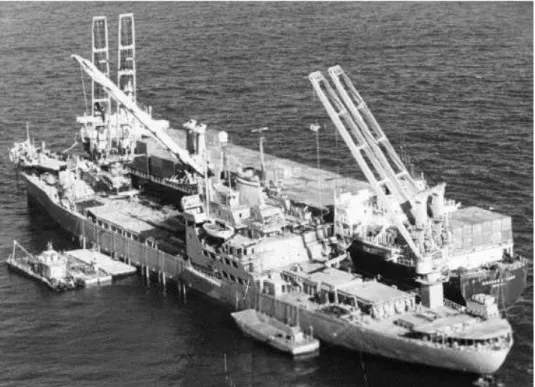
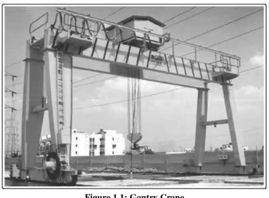
Furthermore, variations of the system parameters, such as the cable length and load weight, are also included. The cable and the load are treated as a spherical pendulum with two degrees of freedom sway. Cranes are used to move a load from point to point in minimum time so that the load reaches its destination without swaying.
In the first approach, the operator is kept in the loop and the dynamics of the load are changed to make his job easier. The second technique is based on feedback of the position and swing angle. Ridout (1989a) developed a controller which feedbacks the position and speed of the trolley and the load swing angle.
However, if the length of the cable is changed in an unqualified manner, the performance of the system will deteriorate. As mentioned earlier, the goal of crane steering is to move the load from point to point while minimizing load swing. It controls swing damping with appropriate feedback on swing angle and swing speed.
However, the effect of load mass is neglected in tracking controller design.
Friction Compensation
This movement is slow and therefore variations in cable length can be considered a disruption to the system. The effect of cable length variations is then examined through simulation to ensure that performance does not deteriorate. However, few studies include lifting in controller design (e.g. Auernig and Troger, 1987).
However, Lee (1998) and Omar and Nayfeh (2001) consider it in the design of controllers for gantry and tower cranes. From these studies, we find that for very heavy loads compared to the trolley weight, system performance degrades if the load weight is not included in the controller design. Although it can alleviate frictional effects, it can also excite high-frequency harmonics in the system.
Compensation can be done on-line to track friction changes that may occur due to environmental changes and mechanical wear. Among these models, we choose the one proposed by Canudas et al. 1986) because of its simplicity and because it represents most of the friction phenomena observed in our experiment, Figure 3.1.
METHODOLOGY
Introduction
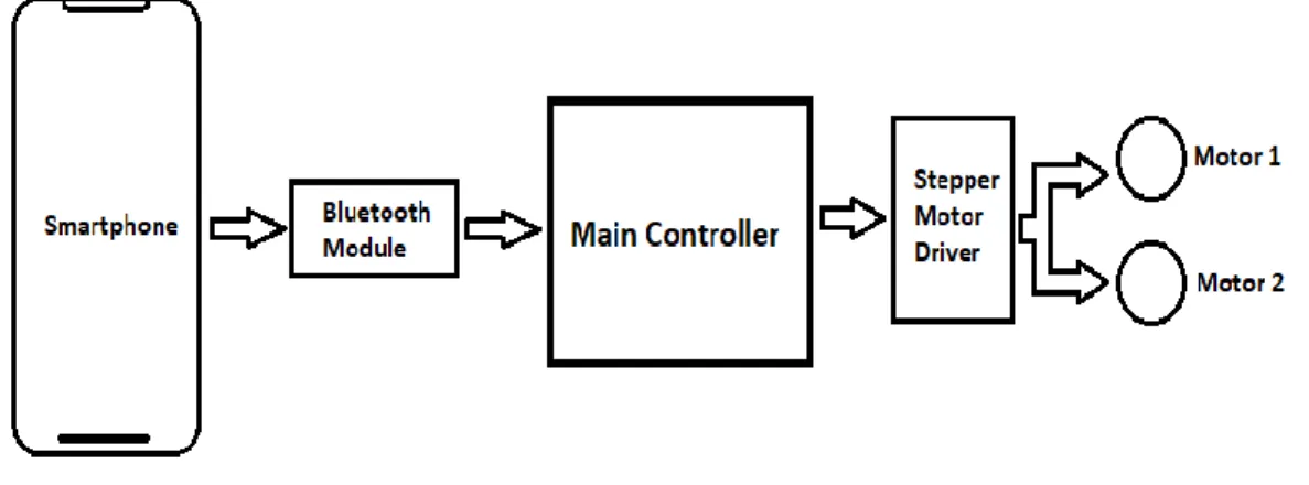
Block Diagram
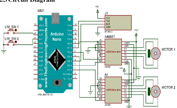
In this circuit, we have used Arduino NANO as the main controller of the system. The transmitter pin of the Bluetooth module is connected to pin 7 of the controller and the receiver pin of the Bluetooth module is connected to pin 4 of the controller. Limit switch 1 is connected to pin A0 of the controller and limit switch 2 is connected to pin A1 of the controller.
For motor 1 we connected the DIR (direction) pin to pin 2 of the controller. For motor 2, the DIR pin is connected to pin 3 of the controller and STEP pin is connected to pin 6 of the controller. The characters are, "l" to move the shifter left, "r" to move the shifter right, "u" to lift the loads and "d" to lower the loads.
After launching the app we must connect to the Bluetooth module of the system. To connect to the Bluetooth module, we must first open the app called “Bluetooth SPP Pro”. After connecting to the module, we must select the keyboard mode to enter the control panel.
We set the buttons this way; we place the character “l” on the left button, “r” on the right button, “u” on the up button and finally “d” on the down button. After setting up the buttons, we are now ready to send commands to the controller. To move the slider motor to the right, we press the "Right" button, which sends the "r" character to the controller and the controller moves the slider motor to the right.
To move the slide motor to the left, press the "Left" button, which will send the "l" character to the controller.
HARDWARE AND COMPONENT DESCRIPTION
Introduction
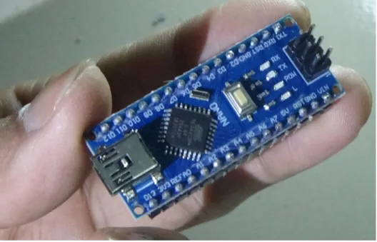
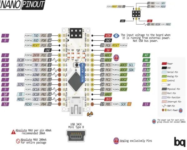
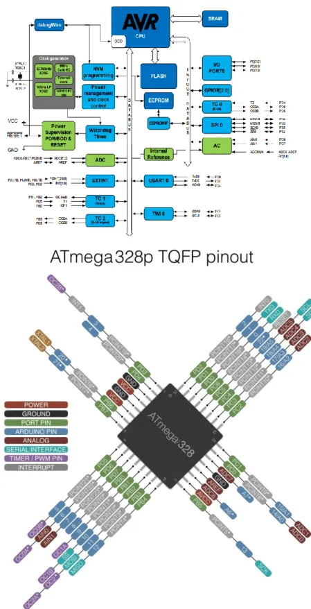
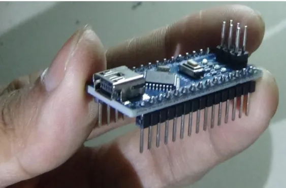
Arduino NANO
- Microcontroller: ATMEGA328P
- Types
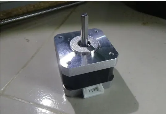
- Two-phase stepper motors
- Unipolar motors
- A4988 Motor Driver Pin out
- Power Connection Pins
- Micro step Selection Pins
- Control Input Pins
- Pins For Controlling Power States
- Output Pins
- Cooling System – Heatsink
- Current limiting
- Wiring A4988 stepper motor driver with Arduino UNO
- Pin configuration
- HC-06 Features and Electrical characteristics
- HC-06 Bluetooth Module Advantages
- How to use HC-06 Bluetooth Module
- Applications
The motor position can then be commanded to move and hold at one of these steps without any position sensor for feedback (open loop controller) if the motor is carefully sized for torque and speed for the application. In order for the motor shaft to rotate, one electromagnet is first energized, which magnetically attracts the pinion gears. Because of this, multi-phase stepper motors usually have multiple wires (or conductors) to control the motor.
Often these two phase commons are internally connected so that the motor has only five wires. Dithering the stepper signal at a higher frequency than the motor can respond to will reduce this "static friction" effect. According to the data sheet, the motor supply requires suitable decoupling capacitor close to the board capable of sustaining 4A.
For example, if you choose to run NEMA 17 with 1.8° or 200 steps per revolution in quarter-step mode, the motor will provide 800 microsteps per revolution. These three microstep select pins are pulled LOW by internal pull-down resistors, so if we leave them disconnected, the motor will operate in full-step mode. Each HIGH pulse sent to this pin steps the motor by the number of microsteps set by the Microstep Selection Pins.
Pulling it UP turns the motor clockwise and pulling it LOW turns the motor counterclockwise. If you just want the motor to rotate in one direction, you can connect DIR directly to VCC or GND accordingly. You can use this especially when the engine is not in use to save energy.
Home state is basically the initial position from which the motor starts and it is different depending on the microstep resolution. However, the amount of current delivered to the motor depends on the system's power supply, cooling system and current limiting setting. We need to limit the maximum amount of current flowing through the stepper coils and prevent it from exceeding the rated current of the motor.
You must set the current limit so that it is equal to or less than the current rating of the motor. Also keep the microstep select pins loose to run the motor in full step mode.
Coupling
Due to the large sliding contact area between their male and female members, threads have greater frictional energy losses compared to other couplings. Spindles are commonly used in linear actuators, machine slides (such as in machine tools), vises, presses, and jacks. A lead screw is sometimes used with a split nut, also called a half nut, which allows the nut to be loosened from the threads and moved axially, independently of the rotation of the screw, when necessary (such as in single point threading on a manual lathe).
Coupling selection, installation and maintenance can lead to reduced maintenance time and maintenance cost. One main function is to transfer power from one end to the other (eg: motor to pump transfer power through coupling). To provide for the connection of the shafts of units that are manufactured separately (such as the engine and the generator) and to ensure.
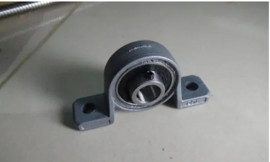
Pillow Block Mounted Bearing
This differs from "plummer blocks" which are bearing housings supplied without any bearings and are usually intended for higher load ratings and a separately installed bearing. The fundamental application of both types is the same, that is to mount a bearing securely so that its outer ring can stand still while the inner ring allows rotation. Split type enclosures are usually two-piece enclosures where the shell and base can be detached, while others may be single-piece enclosures.
Various sealing arrangements can be provided to prevent dust and other contamination from entering the housing. The housing therefore provides a clean environment for the environmentally sensitive bearing to rotate free of contamination, while also retaining lubrication, either oil or grease, which increases performance and duty cycle. However, various grades of metals can be used to manufacture the same, including ductile iron, steel, stainless steel, and various types of thermoplastic and polyethylene-based plastics.
The bearing element can be made of 52100 chromium steel alloy (most common), stainless steel, plastic, or bushing materials such as SAE660 cast bronze or SAE841 oil impregnated sintered bronze, or synthetic materials. An angle bracket or angle bracket or angle clip is an L-shaped fastener used to join two parts generally at a 90 degree angle. It is usually made of metal, but it can also be made of wood or plastic.
Its typical use is to attach a wooden shelf to a wall or to join two pieces of furniture together. When the holes are enlarged to allow for adjustments, the name is angle stretcher or angle contraction plate.
DISCUSSION AND RESULT
- Introduction
- Discussion
- Result
- Conclusion
- Conclusion
- Future Scope
In this project, a prototype of a wireless gantry crane that can be operated by a smartphone has been designed and manufactured. But in the future, we can implement WiFi network system together with the Internet, which will allow us not only to control the crane from a greater distance than Bluetooth, but we can also control the crane from anywhere on the planet over the Internet. We can add a third direction to allow the crane to move loads to anywhere in the room.
Thus, it will allow the physically challenged but educated person to control the crane without any problem.
APPENDIX
Code