UNIVERSITI TEKNIKAL MALAYSIA MELAKA
APPLICATION OF FACILITY LAYOUT SOFTWARE:
CASE STUDY AT ISUZU HICOM MALAYSIA
Thesis submitted in accordance with the partial requirements of the Universiti Teknikal Malaysia Melaka for the Bachelor of Manufacturing Engineering
(Manufacturing Management) with Honours
By
MOHAMAD MUKHLIS BIN ABU BAKAR
UTeM Library (Pind.1/2005)
SULIT
TERHAD
TIDAK TERHAD
(Mengandungi maklumat yang berdarjah keselamatan atau kepentingan Malaysia yang termaktub di dalam AKTA RAHSIA RASMI 1972)
(Mengandungi maklumat TERHAD yang telah ditentukan oleh organisasi/badan di mana penyelidikan dijalankan)
(TANDATANGAN PENULIS)
Alamat Tetap:
No. 16 Jalan 1/14, Taman Bukit Indah 68000 Ampang, * Tesis dimaksudkan sebagai tesis bagi Ijazah Doktor Falsafah dan Sarjana secara penyelidikan, atau disertasi bagi pengajian secara kerja kursus dan penyelidikan, atau Laporan Projek Sarjana Muda (PSM). ** Jika tesis ini SULIT atau TERHAD, sila lampirkan surat daripada pihak berkuasa/organisasi berkenaan dengan menyatakan sekali sebab dan tempoh tesis ini perlu dikelaskan sebagai SULIT atau TERHAD.
BORANG PENGESAHAN STATUS TESIS* UNIVERSITI TEKNIKAL MALAYSIA MELAKA
JUDUL: APPLICATION OF FACILITY LAYOUT SOFTWARE:
CASE STUDY AT ISUZU HICOM MALAYSIA
SESI PENGAJIAN: 2009-2010
Saya _____________________________________________________________________ mengaku membenarkan tesis (PSM/Sarjana/Doktor Falsafah) ini disimpan di
Perpustakaan Universiti Teknikal Malaysia Melaka (UTeM) dengan syarat-syarat kegunaan seperti berikut:
1. Tesis adalah hak milik Universiti Teknikal Malaysia Melaka.
2. Perpustakaan Universiti Teknikal Malaysia Melaka dibenarkan membuat salinan untuk tujuan pengajian sahaja.
3. Perpustakaan dibenarkan membuat salinan tesis ini sebagai bahan pertukaran antara institusi pengajian tinggi.
4. **Sila tandakan (√)
DECLARATION
I hereby, declare this thesis entitled “Application of facility layout software: case study at Isuzu Hicom Malaysia” is the result of my own research expect as cited in references.
Signature
:………
Author’s Name:
:...………
APPROVAL
This thesis submitted to the faculty of Manufacturing Engineering of UTeM as partial fulfillment of the requirements for the degree of Bachelor of Manufacturing Engineering (Engineering
Management) with Honors. The member of the supervisory committee is as follow
………
ii
ABSTRACT
iii
ABSTRACT
iv
DEDICATION
v
ACKNOWLEDGEMENTS
Alhamdulillah, thanks to Allah the Almighty for His will, I have the chance to finish up my Projek Sarjana Muda 2 (PSM 2) report from the very word till end point within the specified period.
First of all, I want to express my appreciation to my PSM supervisor, DR.NOOR AJIAN MOHD LAIR for his supervision, comments and guidance in order to make sure I can gain as much experience and knowledge to complete my PSM 2 report. I also want to would like to express my gratitude to HASALOAN HAERY PIETER as my examiner. I really appreciate the kindness and thoughts. Thank you.
I also want to pay compliment to my family. Their undivided love and support are the beacons that have continued to motivate me through the harshest of situations and I believe it will also spur me on to greater achievement in the future.
vi
1.0 The Concept Of Facilities Layout ... 1
1.1 Problem Statement ... 2
1.2 Research Objective ... 3
2.1 Background of Facilities Layout... 8
2.2 Objective of Facility Layout ... 9
2.3 Types of Facilities Layouts ... 10
2.4 Non-Traditional Types of Layout ... 13
2.5 Why We Need Facility Layout ... 17
vii
CHAPTER 3 ... 27
Rearch methodologi and CONCEPT OF CRAFT ... 27
3.0 Introduction ... 27
3.1 Experimental Design... 27
3.2 Background of CRAFT Method ... 30
3.3 Advantages of Method ... 33
3.4 Disadvantages of Method ... 33
3.5 CRAFT Algorithms ... 34
3.6 Conclusion ... 34
CHAPTER 4 ... 36
ORGANIZATION BACKGROUND ... 36
4.0 Introduction ... 36
4.1 Company profile ... 36
4.2 Objectives of Company ... 40
4.3 Vision of Isuzu Hicom Malaysia Sdn.Bhd. ... 41
4.4 Mission of Isuzu Hicom Malaysia Sdn.Bhd. ... 41
4.5 Company’s product ... 42
4.6 Production flow process ... 45
4.7 Departments at Isuzu Hicom Malaysia ... 47
4.8 Revised the Existing Layout ... 56
4.8 Conclusion ... 58
CHAPTER 5 ... 59
CRAFT SOFTWARE ... 59
5.0 INTRODUCTION ... 59
viii
5.2 Craft software in visual basic ... 60
5.5 Transfer from (x, y) input to matrix input ... 65
5.6 Summation distance between department centriods ... 66
5.6 Conclusion ... 68
6.7 Comparison across layout ... 82
6.8 Conclusion ... 83
Chapter 7 ... 84
CONCLUSION ... 84
7.0 Introduction ... 84
7.1 Background of Research ... 84
7.2 Research Findings ... 85
7.3 Recommendation for further research ... 86
ix
LIST OF FIGURE
Figure 1. 1 The research methodology ... 5
Figure 2. 1 Flowline (Product) layout. (Sources: Plant Location and Layout, (Abha Kumar, 2003)) ……….10
Figure 2. 2 Functional (Process) layout. (Source: Plant Location and Layout, Abha Kumar, 2003)) ... 10
Figure 2. 3 Cellular (Group) layout.(Source: Operation Management, Stevenson)11 Figure 2. 4 A U-shaped production line (Source: Operation Management, Stevenson) ……….11
Figure 3. 1 Experimental design ... 28
Figure 3. 2 Solution Quality and Solution Time of Solution Approaches to Facility Layouts Problems. (Sources: Construction Heuristics, Thonemann) ... 32
Figure 4. 1 Logo of Isuzu Malaysia ... 37
Figure 4. 2 Map of Peninsula Malaysia and the location of the ... 38
Figure 4. 3 Area view of Isuzu HICOM Malaysia Sdn Bhd (IHMSB) ... 38
Figure 4. 4 Organisation chart for Isuzu HICOM Malaysia Sdn Bhd (IHMSB).... 40
Figure 4. 5 MTB 145 Figure 4. 6 MTB 140 crew ... 42
Figure 4. 14: Workers assemble... ... 45
Figure 4. 15 : White body truck is paint at Paint Shop ... 46
x
Figure 4. 17 : Finish truck is going to Tester Line ... 47
Figure 4. 18 Isuzu Hicom Malaysia Sdn.Bhd. General Layout ... 48
Figure 4. 19 Layout in body shop ... 49
Figure 4. 20 Trim & Final 2 Layout ... 50
Figure 4. 21 Layout in Workshop ... 51
Figure 4. 22 General flows across department... 57
Figure 5. 1 The pseudo code for reading input data. ... 61
Figure 5. 2 Flow of Craft Software... 62
Figure 5. 3 The pseudo code for randomly generate layout design ... 63
Figure 5. 4 The pseudo code for Randomly generate layout design ... 64
Figure 5. 5 The pseudo code for calculate department centriod ... 65
Figure 5. 6 Coordinate of X and Y ... 65
Figure 5. 7 The pseudo code for transfer from (x, y) input to matrix input ... 66
Figure 5. 8 The pseudo code for Euclidean distance ... 67
Figure 5. 9 The pseudo code for summation distance between department centriods ………...68
Figure 6. 1 Figure of current layout ... 71
Figure 6. 2 Result of detail exchange from Craft ... 72
Figure 6. 3 Result of Differences current layouts with new layout_1 ... 72
Figure 6. 4 New Layout_1 ... 73
Figure 6. 5 Result of detail exchange from Craft ... 74
Figure 6. 6 Result of Differences current layouts with new layout_2 ... 74
Figure 6. 7 New Layout_2 ... 75
Figure 6. 8 Result of detail exchange from Craft ... 76
Figure 6. 9 Result of Differences current layouts with new layout_3 ... 76
Figure 6. 10 Result of detail exchange from Craft ... 78
Figure 6. 11 Result of Differences current layouts with new layout_4 ... 78
Figure 6. 12 New Layout_4 ... 79
Figure 6. 13 Result of detail exchange from Craft ... 80
Figure 6. 14 Result of Differences current layouts with new layout_5 ... 80
xi
LIST OF TABLE
Table 2. 1 Summaries of literature review ... 19
Table 4. 1 Data of size and building area ... 54
Table 4. 2 Grouped departments after revised ... 56
1
CHAPTER 1
INTRODUCTION
1.0 The Concept Of Facilities Layout
Facility layout is an arrangement of machines, departments, workstations, storage areas, aisles, and areas within an existing or proposed facility. (Irani and Huang,2000) Layouts have far-reaching implications for the quality, productivity, and competitiveness of a firm. Layout decisions significantly affect how efficiently workers can do their jobs, how fast goods can be produced, how difficult it is to automate a system, and how responsive the system can be to changes in product or service design, product mix, and demand volume (Abha Kumar, 2003).
They are three basic common type of layout that is use in Manufacturing. They are process layout, product layout, and fixed-position layout. Each type of layout plays a different role or different purpose.
2
a)Minimum Handling of Materials:
A good plant layout takes into consideration the various flows of materials inside the plant this can minimizing the handling of materials. The choice of the material handling equipment and the systems of storage of materials, have a lot to do with the way the plant facilities are laid out.
b)Minimum Damage and Spoilage of Materials:
If adequate consideration regarding handling and storage of materials is given, it automatically minimizes damage and spoilage of materials.
c)Reduced Congestion of Materials, Machinery and Men:
A good physical layout should eliminate confusion in the plant. By doing, it not only makes the life of the supervisor easier but also contributes towards overall improvements in the productivity of the shop.
d)Flexibility with Regard to Changing Production Conditions:
3
they produce about eight types of vehicle and they are only one type for the passenger vehicle and the rest are for the commercial vehicle like medium and heavy duty trucks.
The plant at Pekan, Pahang was build on 1994, and the area cover about 100 acre and occupying plant facilities like production building, offices, gatehouse, and warehouses. As an old factory building the with the limited worker which have a knowledge about the Facilities Layout, the arrangement of the factory department and machine are not in smooth flow. Therefore the optimum space utilization does not garneted. As a result, problem such as long products and workers travel distance, which lead to waste the time, is an obvious incident.
1.2 Research Objective
In general the objective of this research is to design a new layout that can be improved the space utilization of the Isuzu Company.
The specific objectives of this research are listed below:
i. To identify the performance measure suitable for facility layout ii. To design the new improved layout
1.3 Research Scope
4
1.4 Research Methodology
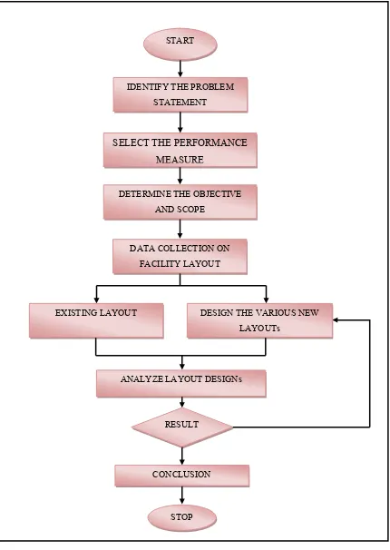
The methodology for this research is as an illustrated in Figure 1.1.
Basically, the first step is to identify the problem that occurs in the industry. After finding and understand what is the problem, the second step is to identify what are the best tools or technique that can be used to solve the problem base on the situation. For this research, the method used to optimize the layout is CRAFT method. CRAFT is selected because of its ability to capture the initial layout with reasonable accuracy. Then, collection of the data is conducted to have a correct input for this research. Using all the data that have been collect and the method that have been use, a new layout is generated. Analyze the new layout with the old layout. The final step is to form a conclusion about the information that whatever the new layout are make any improvement or not.
The progress of this research following the given methodology is as illustrated in Table 1.1. Overall the project has program as planned.
1.5 Organization Of Report
5
Figure 1. 1 The research methodology
START
STOP
IDENTIFY THE PROBLEM STATEMENT
SELECT THE PERFORMANCE MEASURE
EXISTING LAYOUT
DETERMINE THE OBJECTIVE AND SCOPE
DATA COLLECTION ON FACILITY LAYOUT
DESIGN THE VARIOUS NEW LAYOUTs
ANALYZE LAYOUT DESIGNs
RESULT
6
Chapter 2 presents the literature review on the background and basic information about the facility layout. By understand the basic of the facilities layout and the type of facilities. It may enhance the progress of this research. It reviews some basic tools that used for this facilities layout problem.
Chapter 3 presents the methodology used for conduct this research. It describes what is the CRAFT method and the uses of the tools in this research. This chapter included the background, the procedure, advantage and disadvantage of the tools.
Chapter 4 present case study for the activities concluded to get the input data. This chapter is explained about the company background and the department that IHM have. The layout of the company is also being attached.
Chapter 5 describe about the outlines the procedure adopted for developing algorithms for the craft software. For building this software Visual Basic (VB) is chosen because it was originally created to make it easier to write programs for the Windows computer operating system.
Chapter 6 presents the result and analysis performed in this research. Specifically, 5 new layouts are developed using the craft software. The flow distance of each of the layouts is then calculated using Euclidian distance formula. This chapter included the Comparison across the layouts.
7
CHAPTER 2
LITERATURE REVIEW
2.0 Introduction
Facilities layout concerns with finding an arrangement for work areas and equipments such that optimum performance can be achieved. A good layout minimizes handling of materials, minimizes raw materials damage, reduced conjunction and ensure layout flexibility. Those elements contribute significantly towards factory performance.
8
2.1 Background of Facilities Layout
Facility layout refers to the arrangement of machines, departments, workstations, storage areas, aisles, and areas within an existing or proposed facility. (Irani and Huang,2000) Layouts have far-reaching implications for the quality, productivity, and competitiveness of a firm. Layout decisions significantly affect how efficiently workers can do their jobs, how fast goods can be produced, how difficult it is to automate a system, and how responsive the system can be to changes in product or service design, product mix, and demand volume (Abha Kumar, 2003). Therefore, it is necessary to have the best layout design so that the factory operations at the optimum performance.
The determination of the best layout for a facility is a classical industrial engineering problem. The prime interest in a facilities-design problem is to determine a layout that optimizes some measure of production efficiency. The layout problem is applicable to many environments like warehouses, banks, airports, manufacturing system and many more. Each of the above applications has distinct characteristic. Some of the common objectives in any facilities-design problem as seen in would be (Nahmias 2004):
i. to minimize cost investment for production ii. to utilize available space efficient
iii. to minimize material handling cost iv. to reduce work in progress
9
sequence of steps and set of conversations for identifying and evaluating various activities and alternatives involved in any layout design procedure.
Selection of an appropriate layout for multi-product facility poses a major challenge since the best decomposition of its material flow network is usually achieved by a hybrid layout that must combine the flow and machine grouping attributes of the three traditional layouts. But SLP design process does not describe specific method for design of batch layouts. It lacks a systematic method in varying the manufacturing focus on the batch can be composed (Muther,1973).
An effective strategy to eliminate the limitations of SLP is to combine it with another technique known as production flow analysis (PFA) which is:
i. Incapability of generating layouts that are hybrid combination of Functional and Cellular layout.
ii. Incapability of product routings, instead of the From-to-Chart as input data.
A layout module is defined as a group of machines connected by a material flow that exhibits a flow pattern characteristic of a specific type layout such as Functional, Flowline, Fixed-position, Cellular or Hybrid Layout (Buffa, 1964).
2.2 Objective of Facility Layout
An efficient Facility layout is one that can be instrumental in achieving the following objectives (Irani and Huang (2000):
i. Improve productivity.
ii. Minimize overall production time and material handling cost. iii. Provide enough production capacity.
iv. Facilitate manufacturing process.
10
2.3 Types of Facilities Layouts
There are several alternative layout types that are appropriate for different product mixes and production volumes. Determination of the layout type is a major design decision because it impacts on so many other aspects of the production system. Three type of layout are considered appropriate for a manufacturing facility which are Flowline (Product), Functional (Process) and Cellular (Group) (Buffa, 1964).
Figure 2. 1 Flowline (Product) layout. (Sources: Plant Location and Layout, (Abha Kumar, 2003))