UNIVERSITI TEKNIKAL MALAYSIA MELAKA
PROGRAMMING AND INTERFACING OF
MASTER SLAVE (PARENT-CHILD) ROBOT
FOR PAINTING APPLICATION
Thesis submitted in accordance with the requirements of the University Technical
Malaysia Malacca for the Degree of Bachelor of Engineering (Honours)
Manufacturing (Robotic and Automation)
By
KUTKM Library (Pind.1/2005)
SULIT
TERHAD
TIDAK TERHAD
(Mengandungi maklumat yang berdarjah keselamatan atau kepentingan Malaysia yang termaktub di dalam AKTA RAHSIA RASMI 1972)
(Mengandungi maklumat TERHAD yang telah ditentukan oleh organisasi/badan di mana penyelidikan dijalankan)
(TANDATANGAN PENULIS)
* Tesis dimaksudkan sebagai tesis bagi Ijazah Doktor Falsafah dan Sarjana secara penyelidikan, atau disertasi bagi pengajian secara kerja kursus dan penyelidikan, atau Laporan Projek Sarjana Muda (PSM). ** Jika tesis ini SULIT atau TERHAD, sila lampirkan surat daripada pihak berkuasa/organisasi berkenaan dengan menyatakan sekali sebab dan tempoh tesis ini perlu dikelaskan sebagai SULIT atau TERHAD.
BORANG PENGESAHAN STATUS TESIS* UNIVERSITI TEKNIKAL KEBANGSAAN MALAYSIA
JUDUL: PROGRAMMING AND INTERFACING OF MASTER SLAVE ROBOT FOR PAINTING APPLICATION
SESI PENGAJIAN: 2006-2007
Saya _____________________________________________________________________
mengaku membenarkan tesis (PSM/Sarjana/Doktor Falsafah) ini disimpan di Perpustakaan Universiti Teknikal Malaysia Melaka (UTeM) dengan syarat-syarat kegunaan seperti berikut:
1. Tesis adalah hak milik Universiti Teknikal Malaysia Melaka.
2. Perpustakaan Universiti Teknikal Malaysia Melaka dibenarkan membuat salinan untuk tujuan pengajian sahaja.
3. Perpustakaan dibenarkan membuat salinan tesis ini sebagai bahan pertukaran antara institusi pengajian tinggi.
4. **Sila tandakan (√)
ASRU ROZIMIN B ABU BAKAR
DECLARATION
I hereby, declare this thesis entitled “Programming and Interfacing of Master Slave
(Parent -Child) Robot” is the result of my own research except as cited in the reference.
Signature :………..
Author’s name :………..
APPROVAL
This thesis submitted to the senate of UTeM and has been accepted as partial fulfillment of the requirements for the degree of Bachelor of Manufacturing Engineering (Robotic and Automation). The members of the supervisory committee are as follow:
………
Main Supervisor
ABSTRACT
ABSTRAK
Projek ini membuktikan teknologi robot ‘Tuan-Hamba’. Ia berpotensi untuk diakplikasi
ACKNOWLEDGEMENTS
This appreciation is expressed to those who have given generous contributions within the period of this thesis development to fulfill the requirement of the Degree of Bachelor of Engineering (Honours) Manufacturing (Robotic and Automation) program.
Here, I would like to thanks to my supervisor, Mr. Samsi bin Saad because given a title for my PSM, support and guidance me during my thesis. I appreciate his continuous direction and opinion regarding this project. Furthermore, the guide and help of him make this thesis more effective and valuable.
Finally, I would like to thank to all lectures, technicians and colleagues who had involved directly or indirectly in my thesis. I also would like to thank the college for providing all the equipments as well as materials needed to fabricate my project.
iii
DEDICATION
TABLE OF CONTENT
1.3 The Importance of Project ……….……….. 3
v
2.6 Software……….………..…………19
2.6.1 Relationship to hardware………..……….20
2.6.2 Relationship to data………..……….20
LIST OF FIGURE
Figure 1: Conceptual figures of systems……….……..……1
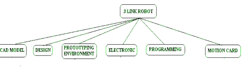
Figure 2: Three link of robot……….…..……. 2
Figure 3: Part of robot programming system……….……..…….8
Figure 4: eXperimental Platform in Robotics (XPROB) architecture…….………..… . 9
Figure 5: Type of PIC ………..………...12
Figure 6: Basic Stamp ……….………15
Figure 7: A screenshot of computer software ……….………17
Figure 8: System Programming……….…….….26
Figure 9: Different low level and high level language………27
Figure 10: A compiler ……….27
Figure 11: The screenshot of MPLAB software……….….29
Figure 12 : The screenshot of IC pro ……….…… 30
Figure 13: PIC 16F873……….……36
Figure 14: Universal burner for PIC……….….. 36 Figure 15: PIC in universal burner……….….36
Figure 16: Important key in this project………..…38
vii
LIST OF TABLE
CHAPTER 1
PROGRAMMING AND INTERFACING OF MASTER SLAVE
ROBOT
1.1 INTRODUCTION
Now day, the robotic fields have become more expand. New technology being develops and implement in robotic industrial. One of the technologies is master slave robot. The word master slave refers that is two of robot, one is master robot and the other one is slave robot. Master slave mean the slave robot being controlling by the master robot.
The master slave robot can be used for some application such as in nuclear industry, welding, and the industry that involved chemical and poison material to handling by human and so on. For this project, master slave robot is used for painting application. The reason for painting application it is because it easy to implement with UTeM environment.
For this project, the slave robot is developing based on the human arm. The slave robot have three joint related as human arm that is shoulder, elbow and wrist. The slave robot controlled manual by human arm which act as the master to the slave robot.
2
Figure 1: Concept of master slave robot
This project consist of several task. Some of the tasks are
Design.
CAD/CAM modeling.
Simulation.
Circuit.
Hardware and software selection.
Programming and Interfacing
Physical assembly and testing.
Each of tasks is related to each other, so all the information is shared to make sure the robot working properly.
1.2 OBJECTIVES
The objective of this project is to understand the framework of the master slave robot, to develop and programming the robot.
1.3 THE IMPORTANCE OF PROJECT
This framework will facilitate the programming and interfacing of robots.
The prototype robot will be used as an educational tool in the robotics and automatic control classes.
This project will establish a basis and framework for design automation of robot manipulators.
1.4 SCOPE OF PROJECT
1. Research the programming use in master slave robot.
4
CHAPTER 2
LITERATURE REVIEW
2.1 WHAT ARE ROBOTS
A robot is an electro-mechanical device that can perform autonomous or preprogrammed tasks. A robot may act under the direct control of a human (e.g. the robotic arm of the space shuttle) or autonomously under the control of a programmed computer. Robots may be used to perform tasks that are too dangerous or difficult for humans to implement directly (e.g. nuclear waste clean up) or may be used to automate repetitive tasks that can be performed with more precision by a robot than by the employment of a human (e.g. automobile production.)
Robots may be controlled directly by a human, such as remotely-controlled bomb-disposal robots, robotic arms, or shuttles, or may act according to their own decision making ability, provided by artificial intelligence. However, the majority of robots fall in-between these extremes, being controlled by pre-programmed computers. Such robots may include feedback loops such that they can interact with their environment, but do
2. A machine or device that operates automatically or by remote control.
Typical applications of robots include welding, painting, ironing, assembly, pick and place, palletizing, product inspection, and testing, all accomplished with high endurance, speed, and precision.
2.1.1 Defining Parameters
6
Kinematics – the actual arrangement of rigid members and joints in the robot, which determines the robot's possible motions. Classes of robot kinematics include articulated, Cartesian, parallel and SCARA.
Working envelope – the region of space a robot can reach.
Carrying capacity – how much weight a robot can lift.
Speed – how fast the robot can position the end of its arm.
Accuracy – how closely a robot can reach a commanded position. Accuracy can vary with speed and position within the working envelope. It can be improved by Robot calibration.
Motion control – for some applications, such as simple pick-and-place assembly, the robot need merely return repeatably to a limited number of pre-taught
positions. For more sophisticated applications, such as arc welding, motion must be continuously controlled to follow a path in space, with controlled orientation and velocity.
Power source – some robots use electric motors, others use hydraulic actuators. The former are faster, the latter are stronger and advantageous in applications such as spray painting, where a spark could set off an explosion.
Drive – some robots connect electric motors to the joints via gears; others connect the motor to the joint directly (direct drive).
Degrees of freedom of a system
The number of independent variables (or coordinates) required to completely
specify the configuration of the mechanical system.
While the above definition of the number of degrees of freedom is motivated by the need to describe or analyze a mechanical system, it also is very important for controlling or driving a mechanical system. It is also the number of independent inputs required to drive all the rigid bodies in the mechanical system.
Kinematic chain
A system of rigid bodies connected together by joints. A chain is called closed if
it
forms a closed loop. A chain that is not closed is called an open chain.
Serial chain
If each link of an open chain except the first and the last link is connected to two
other links it is called a serial chain.
2.2 ROBOT PROGRAMMING
8
The teach pendant or PC is usually disconnected after programming and the robot then runs on the program that has been installed in its controller. In addition, machine operators often use human machine interface devices; typically touch screen units, which serve as the operator control panel. The operator can switch from program to program, make adjustments within a program and also operate a host of peripheral devices that may be integrated within the same robotic system. These peripheral devices include robot end effectors which are devices that can grasp an object, usually by vacuum, electromechanical or pneumatic devices. Also emergency stop controls, machine vision systems, safety interlock systems, bar code printers and an almost infinite array of other industrial devices are accessed and controlled via the operator control panel.
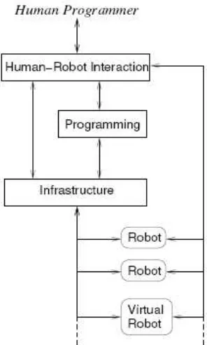
Bruce MacDonald et al [3] state that robot programming systems as having three important conceptual
1. The programming component, including designs for programming language/s, libraries and application programming interfaces (APIs), which enable a programmer to describe desired robot behaviour.
2. The underlying infrastructure including designs for architectures that support and execute robot behaviour descriptions, especially in distributed environments. 3. The design of interactive systems that allow the human programmer to interact
Figure 3: Part of robot programming system
10
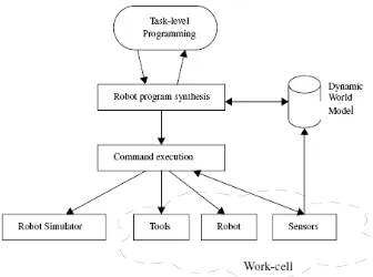
objects’ attributes are updated throughout the execution of the task-level program. In the
program synthesis module, a task planner translates the high level commands into low-level robot commands. A motion planner computes the approaching and final gripper position and orientation. Finally, the low-level commands are translated into robot-dependent instructions. The real-time command execution module forwards these instructions to the corresponding hardware and/or graphically displays them. During the execution of the program, sensor data can be requested. Upon reception, a filter adds a symbolic value to the sensor data. Further reasoning about thse symbolic values allows task re-planning at runtime.
2.3 MICROCONTROLLER
A microcontroller (or MCU) is a computer-on-a-chip used to control electronic devices. It is a type of microprocessor emphasizing self-sufficiency and cost-effectiveness, in contrast to a general-purpose microprocessor (the kind used in a PC). A typical microcontroller contains all the memory and interfaces needed for a simple application, whereas a general purpose microprocessor requires additional chips to provide these functions. A microcontroller is a single integrated circuit, commonly with the following features:
central processing unit - ranging from small and simple 4-bit processors to sophisticated 32- or 64-bit processors
input/output interfaces such as serial ports
peripherals such as timers and watchdog circuits and signal conversion circuits.
RAM for data storage
ROM, EPROM, EEPROM or Flash memory for program storage
clock generator - often an oscillator for a quartz timing crystal, resonator or RC circuit
2.4 PIC MICROCONTROLLER
12
Microchip Technology does not use PIC as an acronym; in fact the brand name is PICmicro. It is generally regarded that PIC stands for Peripheral Interface Controller, although General Instruments' original acronym for the PIC1650 was "Programmable Intergrated Circuit". The original PIC was built to be used with GI's new 16-bit CPU, the CP1600. While generally a good CPU, the CP1600 had poor I/O performance, and the 8-bit PIC was developed in 1975 to improve performance of the overall system by offloading I/O tasks from the CPU. The PIC used simple microcode stored in ROM to perform its tasks, and although the term wasn't used at the time, it is a design that runs one instruction per cycle (4 oscillator cycles).
In 1985 General Instruments spun off their microelectronics division, and the new ownership cancelled almost everything — which by this time was mostly out-of-date. The PIC, however, was upgraded with EPROM to produce a programmable channel controller, and today a huge variety of PICs are available with various on-board peripherals (serial communication modules, UARTs, motor control kernels, etc.) and program memory from 512 words to 32k words and more (a "word" is one assembly language instruction, varying from 12, 14 or 16 bits depending on the specific PICmicro family
Today, the PIC is a complete computer on a chip. Such chips can be built into a device to make the product more intelligent and easier to use.