Abstract—This paper presents the use of meta-heuristic technique to obtain three parameters (KP, KI and KD) of PID
controller for Coupled Tank System (CTS). Particle Swarm Optimization (PSO) is chosen and Sum Squared Error is selected as objective function. This PSO is implemented for controlling desired liquid level of CTS. Then, the performances of the system are compared to various conventional techniques which are Trial and Error, Auto-Tuning, Ziegler-Nichols (Z-N) and Cohen-Coon (C-C) method. Simulation is conducted within Matlab environment to verify the transient response specifications in terms of Rise Time (TR), Settling Time (TS), Steady State Error
(SSE) and Overshoot (OS). Result obtained shows that performance of CTS can be improved via PSO as PID tuning methods.
Index Terms—Coupled Tank System (CTS), Particle Swarm Optimization (PSO), PID Controller, PID Tuning Method.
I. INTRODUCTION
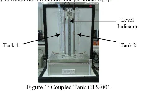
Coupled Tank System (CTS) is one of the applications in industrial production as shown in Figure 1. The process control especially controlling liquid level is important and widely applied in various field such as liquid storage tank, a feeding tank, a product tank, the intermediate buffer containers and water tanks [1-2]. In CTS, the overall process need liquids to be pumped, stored in the tank and pumped again to another tank for certain desired level. The liquid is required to be maintained in a specific height or certain range [3]. Efficient and effective controls of these processes have immense economical advantage and its success depends on the type of control strategy [4].
CTS is a typical representative of the process control. It has nonlinear and complex characteristics. PID controller is implemented to the system to control the desired level of the water and this controller always been used in industrial application due to easy and simple design to implement [5-6]. Nevertheless, the conventional PID controller shows that it is difficult to reach the desired control response with the aim of high speed with short transition time and small overshoot [7]. In order to achieve the optimal specifications, Particle Swarm Optimization (PSO) algorithm is approached. The advantage of PSO is a fast convergence compares with many optimizations [5-6]. It is also easy in its concept and coding implementation.
Manuscript received on May. 2014.
S.Y.S. Hussein, Faculty of Electrical Engineering (FKE), Universiti Teknikal Malaysia Melaka (UTeM).
H.I. Jaafar, Faculty of Electrical Engineering (FKE), Universiti Teknikal Malaysia Melaka (UTeM), Hang Tuah Jaya, 76100 Durian Tunggal, Malaysia .
N.A. Selamat, Faculty of Electrical Engineering (FKE), Universiti Teknikal Malaysia Melaka (UTeM).
F.S. Daud, Faculty of Electrical Engineering (FKE), Universiti Teknikal Malaysia Melaka (UTeM).
A.F.Z. Abidin, Faculty of Electrical Engineering (FKE), Universiti Teknologi MARA (UiTM).
Furthermore, PSO is potential to replace the conventional way of obtaining PID controller parameters [8].
Figure 1: Coupled Tank CTS-001
II. PID CONTROLLER
PID controller is a control feedback mechanism controller which is widely used in industrial control system. PID controller involves three-term control which are the Proportional (P), the Integral (I) and the Derivative (D). PID controller is used to calculate an error value as the difference between a measured process variable and a desired set point. It also used to minimize the error by adjusting the process of control inputs.
) ( )
( 1 ) (
) ( )
( ) ( ) (
t dt de d T dt t e i T t e p K
t dt de d K dt t e i K t e p K t u
(1)
In the system, three parameters are needed to be tuned. One of the parameters is proportional gain, KP. This controller has
the effect of reducing the Rise Time (TR) and Steady State
Error (SSE) but the percentage of the Overshoot (OS) in the system is high. In the integral controller, KI as the integral gain will affect and decrease the rise time. However, it will eliminate the SSE of the system. Even though it eliminates the error but the percentage of the OS is increased and it will affect the Settling Time (TS) as well. In order to improve the
performance of the system, derivative gain, KD in the
derivative controller is introduced. This controller will take action to improve the transient specification and stability of the system. The effects of the each of the controller on a closed-loop system are summarized in Table 1.
Table 1: PID Controller Properties Effect of Performance
TR TS OS SSE
KP Decrease Small
Change Increase Decrease
KI Decrease Increase Increase Eliminate
PID Control Tuning VIA Particle Swarm
Optimization for Coupled Tank System
S.Y.S Hussien, H.I Jaafar, N.A Selamat, F.S Daud, A.F.Z Abidin
Tank 1 Tank 2
KD Small
Change Decrease Decrease
Small Change In order to improve the high stability and short transient response of the system, the optimal gain value must be obtained from the PID tuning. Even though it is only three control parameters, but to adjust the parameter referred to the Table 1 are difficult. Therefore, many methods are implemented in order to obtain the best parameter of PID controller.
III. MATHEMATICAL MODELING
It is vital to understand the mathematics modeling of the behavior of CTS. In this system, the nonlinear dynamic model is observed and the linearization process is done based on the nonlinear model.
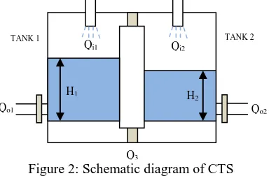
Figure 2: Schematic diagram of CTS
Based on Figure 2, H1 and H2 are the fluid level in Tank 1
and Tank 2. It is measured with respect to the corresponding outlet. Considering a simple mass balance, the rate of change of fluid volume in each tank equals the net flow of fluid into the tank. Therefore, the equation for Tank 1 and Tank 2 are:
3
Bernoulli’s equation for steady, non-viscous, incompressible shows that the outlet flow in each tank is proportional to the square root of the head of water in the tank. Similarly, the flow between the tanks is proportional to the square root of the head differential. Thus:
1 substitute (4), (5) and (6) into (2) and (3), the nonlinear state equations which describe the system dynamics of the CTS
In the second order configuration, h2 is the process variable
and q1 is the manipulated variable and assume that q2 is zero.
The block diagram of the second-order system can be simplified as shown in Figure 3.
Figure 3: Block diagram of second order system Thus, the nonlinear CTS can be obtained as:
1
2
12 21 substituting the parameter which was provided from the [9] and the parameters are shown in Table 2.Table 2: Parameter of CTS
Parameters Value Unit
α3 11.03 cm3/2/sec
A1 32 cm2
A2 32 cm2
Then, all the parameters in Table 1 have been inserted into (9). Thus, the actual transfer function of the plant with the completed value is:
4514 . 0 1565 . 12 9406 . 36
0361 . 0 )
( ) ( ) (
2 1
2
s s
s q
s h s
Gp
(16)
IV. PARTICLE SWARM OPTIMIZATION (PSO)
PSO is introduced by Kennedy and Eberhart [10]. It was first intended for simulation social behavior, as a stylized representation of the movement of organisms in a bird flock or fish school. While searching for food, the birds are either scattered or go together before they locate the place where they can find the food. While the birds are searching for food from one place another, there is always a bird that can smell the food well, that is the bird is perceptible of the place where the food can be found, having the better food resource information. Because they are transmitting the information, especially the good information at any time while searching the food from one place to another, conducted by the good information, the birds will eventually flock to the place where food can be found [11].
The basic principle of the PSO algorithm is it uses a number of particles (agents) that constitute a swarm moving around in the search space looking for the best solution. Each of the particles is treated as a point in N-dimensional space which adjusts its flying according to its own flying experience as well as the flying experience as well as the flying experience of other particles. Each particle keeps track of its coordinates in the solution space which are associated with the best solution (fitness) that has achieved so far by that particle. This value is known as personal best, PBEST. Another best value that
is tracked by the PSO is the best value obtained so far by any particle in the neighborhood of that particle which known as global best, GBEST.
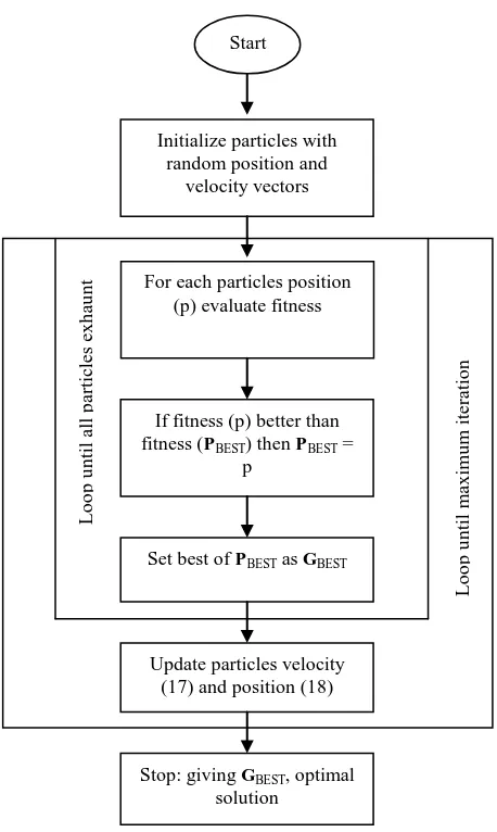
Each particle can be shown by its current velocity and position as shown in (17) and (18). Figure 4 shows the overall process of PSO.
vi+ 1=ωvi + c1r1(PBEST - xi)+ c2r2(GBEST - xi) (17)
xi+ 1= xi+ vi+ 1 (18) where:
vi+ 1 = velocity of particle at iteration k
ω = inertia weight factor c1, c2 = acceleration coefficients
r1, r2 = random numbers between 0 and 1 xi+ 1 = position of particle at iteration k
Figure 4: Flow chart depicting of general PSO
V. RESULTS AND DISCUSSION
The plant of the CTS is obtained from the mathematical modeling in previous chapter. The input voltage injected in the system is 1 Volt and the level converter (gain) will convert the input voltage to the water level. The desired level is 1 cm. The control structure with PID Controller of the CTS is shown in Figure 5 [7].
Figure 5: Control structure with PID Controller Simulation exercise are conducted with AMD Turion 64 X2 Processor, 4GB RAM, Microsoft Window 7 and MATLAB as a simulation platform. In this study, 20 particles are considered with 100 iterations. As default values, c1 and c2 are
set as 2. The initial value of ω is 0.9 and linearly decreased to
0.4 at some stage of iteration. Table 3 shows the optimal PID parameter (KP, KI and KD) obtained using PSO.
Table 3: PID parameter based on PSO Start
Initialize particles with random position and
velocity vectors
For each particles position (p) evaluate fitness
If fitness (p) better than fitness (PBEST) then PBEST =
p
Set best of PBEST as GBEST
Update particles velocity (17) and position (18)
Stop: giving GBEST, optimal solution
Lo
o
p
u
n
ti
l
all
p
arti
cles
e
x
h
au
n
t
Lo
o
p
u
n
ti
l
m
ax
imu
m
it
era
ti
o
Parameter Value
KP 250.9928
KI 4.3478
KD 171.6427
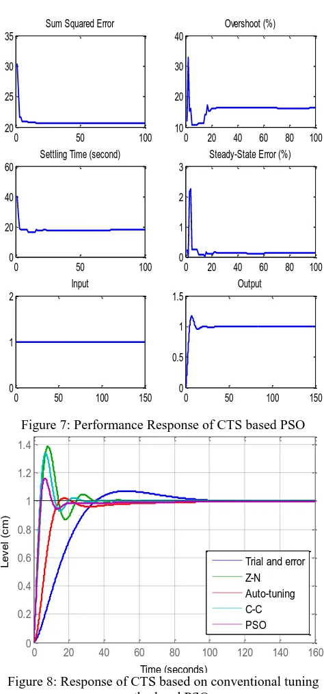
The control structure in Figure 5 is then simulated with the PSO-tuned controller parameter. The response of the system is shown in Figure 6. It shows that, PSO achieved the desired water level and improved the settling time of the system. Table 4 summaries system specifications obtained with PID controller. Figure 7 shows the performance response of the system.
0 20 40 60 80 100 120 140 160
0 0.2 0.4 0.6 0.8 1 1.2 1.4
Response for CTS based on PSO
Time (seconds)
L
e
v
e
l
(c
m
)
Figure 6: Response of CTS based on PSO
Table 4: Performance of CTS based on PSO TS
(sec)
TR
(sec)
OS (%)
SSE (cm)
PSO 17.7519 3.2691 16.1877 0.0000
Figure 8 and Table 5 shows summarize system performances obtained with PID controller. It shows that PSO-tuned method had better performance for CTS compared to the conventional tuning methods which were trial and error, auto-tuning, Z-N and C-C.
0 20 40 60 80 100 0
1 2 3
Steady-State Error (%) 0 20 40 60 80 100 10
20 30 40
Overshoot (%)
0 50 100
0 20 40 60
Settling Time (second)
0 50 100
20 25 30 35
Sum Squared Error
0 50 100 150 0
1 2
Input
0 50 100 150 0
0.5 1 1.5
Output
Figure 7: Performance Response of CTS based PSO
0 20 40 60 80 100 120 140 160
0 0.2 0.4 0.6 0.8 1 1.2 1.4
Conventional Tuning Methods and PSO
Time (seconds)
L
e
v
e
l
(c
m
)
Trial and error Z-N Auto-tuning C-C PSO
Figure 8: Response of CTS based on conventional tuning method and PSO
Table 5: Performances of CTS based on conventional tuning method and PSO
Method TS (sec)
TR
(sec)
OS (%)
SSE (cm) Trial and
error 84.4029 24.0334 6.8592 0.0000
Auto-tuning 53.3368 9.1404 1.8112 0.0000
Z-N 32.0856 3.2943 38.5350 0.0000
C-C 23.5904 2.8105 33.6989 0.0000
PSO 17.7519 3.2691 16.1877 0.0000
VI. CONCLUSION
reduce the values of TS, TR, OS and SSE than conventional
methods. However, this optimization might not be the best tuning method in order to obtain the best parameter for PID controller for CTS. Further research with other optimization is required to compare the performance of the system.
ACKNOWLEDGMENT
Authors would like to thanks Universiti Teknikal Malaysia Melaka (UTeM) for sponsoring this project. This project was conducted under the university short-term grant PJP/2013/FKE(7C)/S01178. Deep appreciations are also dedicated to anyone who directly or indirectly involved in this project.
REFERENCES
[1] M. Abid, “Fuzzy Logic Control of Coupled Liquid Tank System”, International Conference on Information and Communication Technologies, 27-28 August 2005, Karachi, Pakistan, pp. 144-147. [2] M. F. Rahmat and S.M. Rozali, “Modelling and Controller Design for
a Coupled-Tank Liquid Level System: Analysis & Comparison”, Journal of Technology, vol. 48 (D), June. 2008, pp. 113-141. [3] H. Abbas, S. Asghar, S. Qamar, “Sliding Mode Control for
Coupled-Tank Liquid Level Control System”, International Conference on Frontiers of Information Technology, 17-19 Dec. 2012, Islamabad, Pakistan, pp. 325-330.
[4] K. O. Owa, S. K. Sharma, R. Sutton, “Optimised Multivariable Nonlinear Predictive Control for Coupled Tank Applications”, IET Conference on Control and Automation, 4-5 June 2013, Birmingham, England, pp. 1-6.
[5] N. A. Selamat, N. A. Wahab, and S. Sahlan, “Particle Swarm Optimization for Multivariable PID Controller Tuning”, 2013 IEEE 9th International Colloquium on Signal Processing and its Applications, 8-10 March 2013, Kuala Lumpur, Malaysia, pp. 170-175.
[6] H. I. Jaafar, Z. Mohamed, A. F. Z. Abidin and Z. A. Ghani, “PSO-Tuned PID Controller for a Nonlinear Gantry Crane System”, 2012 IEEE International Conference on Control System, Computing and Engineering, 23-25 Nov. 2012, Penang, Malaysia, pp. 515-519. [7] H. I. Jaafar, S. Y. S. Hussien, N. A. Selamat, M. S. M. Aras and M. Z.
A. Rashid, “Development of PID Controller for Controlling Desired Level of Coupled Tank System”, International Journal of Innovative Technology and Exploring Engineering, vol. 3 (9), Feb. 2014, pp. 32-36.
[8] I. M. Khairuddin, A. S. A. Dahalan, A. F. Z. Abidin, Y. Y. Lai, N. A. Nordin, S. F. Sulaiman, H. I. Jaafar, S. H. Mohamad, N. H. Amer, “Modeling and Simulation of Swarm Intelligence Algorithms for Parameters Tuning of PID Controller in Industrial Couple Tank System”, Advanced Materials Research, vol. 903, Feb. 2014, pp. 321-326.
[9] Coupled-Tank Liquid Level Computer-Controlled Laboratory Teaching Package: Experimental and Operation (Service) Manual, Augmented Innovation Sdn. Bhd., Kuala Lumpur, Malaysia. [10] J. Kennedy and R. Eberhart, “Particle Swarm Optimization”,
Proceedings of the 1995 IEEE International Conference on Neural Networks, Perth, WA, 27 Nov. - 1 Dec. 1995, pp. 1942-1948. [11] Q. Bai, “Analysis of Particle Swarm Optimization Algorithm”,
Computer and Information Science, vol 3 (1), February 2010, pp. 180-184.
Sharifah Yuslinda Syed Hussien received her Diploma in Electrical Engineering from Universiti Teknikal Malaysia Melaka (UTeM), in 2011. Currently, she pursues her degree in Electrical Engineering in Control, Instrumentation and Automation System, UTeM.
Hazriq Izzuan Jaafar received his B.Eng degree in Electrical Engineering from Universiti Teknologi Malaysia (UTM), in 2008. He received the M.Eng degree in Mechatronics and Automatic Control engineering also from UTM, in 2013. Currently, he is a
Lecturer at Universiti Teknikal Malaysia Melaka (UTeM) and his interests are in control system and optimization techniques.
Nurasmiza Selamat received her B.Eng degree in Electrical Engineering from Universiti Teknologi Malaysia (UTM), in 2009. She received the M.Eng degree in Mechatronics and Automatic Control engineering also from UTM, in 2013. Currently, she is a Lecturer at Universiti Teknikal Malaysia Melaka (UTeM) and his interests are in control system and optimization techniques.
Fiona Serina Daud received her Diploma in Electrical Engineering from Universiti Teknikal Malaysia Melaka (UTeM), in 2011. Currently, she pursues her degree in Electrical Engineering in Control, Instrumentation and Automation System, UTeM.