Comparison of LQR and PID Controller Tuning
Using PSO for Coupled Tank System
N.A Selamat
1,a, F.S Daud
1,b, H.I Jaafar
1,c, N. H. Shamsudin
1,d1
Faculty of Electrical Engineering,
Universiti Teknikal Malaysia Melaka (UTeM)
[email protected]
a, [email protected]
b, [email protected]
c, [email protected]
dAbstract— Coupled Tank System is one of the widely used applications in industries. Like other process control, it require suitable controller to obtain the good system performances. Hence, this paper presents the study of Coupled Tank System using LQR and PID controller. Both controller parameters are tuned using Single-Objective Particle Swarm Optimization (PSO). The performance of the system is compared based on the transient response in term of of Rise Time (Tr), Settling Time (Ts), Steady State Error (ess) and Overshoot (OS). Simulation is conducted within MATLAB environment to verify the performances of the system. The result shows that both controller can be tuned using PSO, while LQR controller give slightly better results compared to PID controller.
Index Terms— Coupled Tank System (CTS), PID Control, LQR Control, PSO, Single-Objective
I. INTRODUCTION
Coupled Tank System plays an important role in industrial application such as in petro-chemical industries, paper making industries, medical industries and water treatment industries. In industries, the liquid in the tank will go through several processes or mixing treatment whereby the level of liquid needs to be controlled and maintained according to the desired level.
There are several types of controller used to control the coupled tank such as Linear Quadratic Regulator (LQR), Proportional-Integral-Derivatives (PID), Fuzzy Logic, Sliding Mode and Direct Model Reference Adaptive Control. Among the controller, PID is still favorable in industries due to its simplicity, easy to understand structure and robustness [1]. However, several researchers found that LQR is another alternative controller that produces better response compared to PID control strategies and its proved by [2, 3].
Nevertheless, both LQR control and PID control are required proper tuning approach in obtaining good performance. The common approach to select these weighting matrices is via trial and error but this method could be time consuming, cumbersome and result in a non-optimized performance [4, 5]. Conventional tuning also require a good knowledge of the system which is inefficient when applied in modern processes with more complex dynamics [6].
This paper present study of system performance between PID and LQR control schemes for a coupled tank liquid level system with Particle Swarm Optimization (PSO) as the method of tuning. The dynamic model of the system is gathered and obtained from coupled tank liquid level, CTS-001 model.
II.COUPLED TANK SYSTEM
The system under consideration in this paper is coupled tank liquid level system. The main components in Coupled Tanks System are two vertical tanks that joint together by an orifice and separated by a baffle as shown in Fig. 1. Both tanks were also connected with individual inlet liquid pumps and output valves. Coupled tank liquid level principle is to maintain the liquid level inside the tank based on the desired value by regulating the input- output flow rate.
Coupled Tank System can be configured as a Single-Input Single-Output (SISO) or as a Single-Input Multiple-Output (MIMO) system by manipulating the pumps input and sectional area of rotary valves. The model used in this paper is second-order single input single output plant. In the preferred plant the baffle is raised slightly.
The component mass balance of the system as shown in equation (1)-(2) is then derived to represent the system into the mathematical expression.
ܣଵ݀ܪ݀ݐ ൌ ܳଵ ଵെ ܳଵെ ܳଷሺͳሻ
ܣଶ݀ܪ݀ݐ ൌ ܳଶ ଶെ ܳଶെ ܳଷሺʹሻ
where:
H1, H2= height of fluid in tank 1 and 2 respectively
A1, A2= cross-sectional area of tank 1 and 2 respectively
Q03= flow rate of fluid between tanks
Qi1, Qi2= pump flow rate into tank 1 and 2 respectively
Q01, Q02= flow rate of fluid out of tank 1 and 2 respectively
ܳଵൌ ߙଵඥܪଵ ሺ͵ሻ
ܳଶൌ ߙଶඥܪଶ ሺͶሻ
ܳଷൌ ߙଷඥܪଷ ሺͷሻ
whereߙଵ,ߙଶ, and ߙଷ are proportional constants that depends on the coefficients of discharge, the cross sectional area of each orifice and gravitational constant. Combining equation (3),(4) and (5) into (1) and (2) yields a set of nonlinear equations differential equation as shown in (6)-(7).
ܣଵ݀ܪ݀ݐ ൌ ܳଵ ଵെ ߙଵඥܪଵെ ߙଷඥܪଵെ ܪଷ ሺሻ
ܣଶ݀ܪ݀ݐ ൌ ܳଶ ଶെ ߙଶඥܪଶെ ߙଷඥܪଶെ ܪଷ ሺሻ
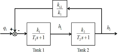
As stated earlier, the model used in this paper is second order process where ݄ଶ is the process variable and ݍଵ is the manipulated variable. The block diagram of second order process is shown in Fig. 2, while the transfer function shown in equation (8). The mathematical representation of the preferred Coupled Tank System as shown (9) is obtained using system identification method where the data was collected from coupled tank liquid level system CTS-001 model.
ܩሺݏሻ ൌ݄ݍଶሺݏሻ ଵሺݏሻ ൌ
݇ଵ݇ଶ
ܶଵܶଶݏଶ ሺܶଵ ܶଶሻݏ ͳ െ ݇ଵଶ݇ଶଵሻ ሺͺሻ
ܩሺݏሻ ൌݏଶ ͲǤͲʹͷͺݏ ͲǤͲͳʹͺͳͲǤͳ͵ͺͺ ሺͻሻ
III.CONTROLLERS A. PID controller
The Proportional-Integral-Derivative (PID) control gives the simplest and yet the most efficient solution to various real-world control problem. The PID control structure as shown in Fig. 3 is also known as “three term” controller and the transfer function is given by (9). Each term in PID has a role to ensure better system performance. P-term reduces error but does not eliminate it, I-term eliminates the error but tend to make the system oscilate, and D-term improves the speed of the responses [7].
Fig. 3. Schematic diagram of PID controller
ܩǤௗሺݏሻ ൌ ܭ ܭͳݏ ܭௗ ሺͻሻ
where Kp is proportional gain, Ki is integral gain and Kd is
derivatives gain. In general, the step of designing PID controller is as follows:
1) Obtain the open loop response and specify the parameter that need to be improved
2) Select Kp to improve rise time, Ki to eliminate
steady state error and Kd to reduce overshoot
3) Adjust Kp, Ki and Kd until the desired overall
response is meet.
Based on PID design procedure, proper tuning of PID gain will determine overall system performance.
B. LQR controller
Linear Quadratic Regulator (LQR) is a state feedback controller which uses state space approach to design and control a system. It is an optimal control technique that considers the state of the dynamic system and control input in determining the optimal control decision [8]. In this method a feedback gain matrix is designed which minimizes the objective function in order to achieve some compromise between the use of control effort, the magnitude and the speed of response that will guarantee a stable system [3]. The main component of LQR controller is state space equation and feedback gain, K as shown in Fig. 4.
ܩ
r y
ܭ ܭ
ܭௗ
ͳȀݏ
ݏ േ
Fig. 2. Block diagram of second order process Fig. 1. Schematic diagram of coupled tank control apparatus
Q01 Q03 Q02
Qi1 Qi2
Tank 1 Tank 2
In LQR controller the system shows in state variable form as shown in (10). All state are assume measureable and seek to find a state-feedback (SVFB) control. Equation (11) show the closed-loop system for LQR controller. It is known that the main objective in LQR controller is to choose the gain K that will minimize the performance index, J (12) and the feedback control law that minimizes the value of the cost is (13).
Fig. 4. Schematic diagram of LQR controller
ݔሶ ൌ ܣݔ ܤݑ ሺͳͲሻ
ݔሶ ൌ ሺܣ െ ܤܭሻݔ ܤݑ ሺͳͳሻ
ܬ ൌͳʹ න ݔஶ ்ܳݔ ݑ்ܴݑ݀ݐ
ሺͳʹሻ
ݑ ൌ െܭݔ ሺͳ͵ሻ
ܣ்ܲ ܲܣ ܳ െ ܲܤܴିଵܤ்ܲ ൌ Ͳ ሺͳͶሻ
ܭ ൌ ܴିଵܤ்ܲ ሺͳͷሻ
For simplification the step in obtaining the state feedback gain, K is as follows:
1) Select design parameter matrices Q and R
2) Solve the Algebraic Riccati Equation (ARE) as shown in (14) to find P
3) Find state feedback gain, K using (15)
Where Q and R are the weight matrices, Q required to be a positive semi-definite n x n matrix and R required to be is positive definite m x m matrix. In obtaining the suitable K value, a suitable tuning of matrices Q and R must first be obtained. The selection of LQR weighting matrices is very significant and it affects the control input [9].
IV.CONTROLLER TUNING
Fig. 5. Schematic diagram of implementation of optimization technique to control system
Either PID or LQR controller, both require proper and fine parameter tuning in order to obtain desired system performance. Common method that still being used until now is manual trial and error method. The method is undesirable due to time consuming, inefficient and required experience worker. Hence this paper will implement optimization technique as a tool in tuning the parameter as shown in Fig. 5. The preferred optimization technique is Particle Swarm Optimization (PSO).
A. Particle Swarm Optimization
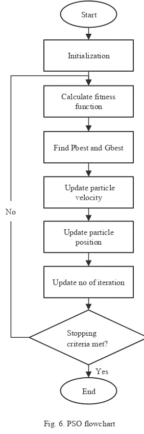
Fig. 6. PSO flowchart
Optimization is a process of obtaining the best or optimal solution while satisfy the constraint. Nowadays, there are varieties of optimization technique available to be chosen from. PSO is one of the popular optimization techniques in the fields.
Particle Swarm Optimization was first introduced by James Kennedy and Russel Eberhart in 1995. It is optimizations that mimic the behavior of social sharing of a ݔሶ ൌ ܣݔ ܤݕ
ݕ ൌ ܥݔ ܰഥ
ܭ േ
r
x y
Controller Optimization
Fitness
Plant
+
+ +
-Input
Start
Initialization
Calculate fitness function
Find Pbest and Gbest
Update particle velocity
Update particle position
Update no of iteration
End Yes No
Stopping criteria met?
swarm such as fish schooling or birds flocking. For instances, each particle can be represents as a bird, while the swarm model as particles in space. An example of bird work moving in swarm is while searching for food in fields. Several group of swarm bird will fly scatter in a field at which will then gather together once the location with most food is found. The swarm of particle or bird communicates through adjustment of velocity and position. Fig 6 shows the flowchart of PSO algorithm.
The principles or flow of PSO algorithm can be simplified as follows [10]:
1. Initialize a group of particles including the random positions, velocities and acceleration of particles. 2. Evaluate the fitness of each particle.
3. Compare the individual fitness of each particle with previous pbest. If it is better, update as new pbest. 4. Compare the individual fitness of each particle with
previous gbest. If it is better, update as new gbest. 5. Update velocity and position for each particle. 6. Go back to step 2 and repeat all the step until
stopping criteria is met
Table 1: PSO initialization parameter Initialization
No. of particles=20 No. of counter=10 Search range=0 to 100 No. of iteration=100
Initialization for velocity
Constant, (c1, c2)=2 Minimum weight, wmin=0.4
Max. velocity=π/1000 Maximum weight, wmax=0.9 Some parameter in PSO is requiring a limitation. Hence in this paper the no of particles is set to 20 and the searching range is set from 0 to 100. All the parameter is being set during initialization and shown in Table 1. Stopping criteria is also one of the parameter that required being set. There are several options of stopping criteria can be chosen from as stated in [11]. In this paper, there are two stopping criteria; termination when there is no improvement observed over a number a number of iteration and when the number of maximum iteration is reached.
As stated earlier PSO is work based on the adjustment of position and velocity; the equation is given in (16) and (17) respectively.
Fitness function is another important criterion in PSO. It is required in order to evaluate how well the system performs or how close the systems operate according to the desired. For the purpose of this study single-objective Integral Time Square Error (ITSE) is chosen.
B. PID parameter tuning
In PID controller there are three parameter that will be tuned which are Proportional (Kp), Integral (Ki) and
Derivatives (Kd) as shown in equation (9).
C. LQR parameter tuning
For LQR control there also three parameter will be tuned which are R, Q1 and Q2. Where Q is a positve semi-definite n
x n matrix and R is positive definite m x m.
V. RESULT AND DICUSSION
The plant used in this research is shown in equation (9), where the data is obtained from coupled tank system, CTS 001 model. The desired level of the liquid is set to be 1cm high that will be control using PID and LQR controller. Both controller parameters will be tune using PSO.
Fig. 7. ITSE value with 10 times simulation for LQR
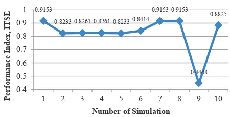
Fig. 8. ITSE value with 10 times simulation for PID
0.4972
0.4028 0.4028 0.4028 0.4028 0.679
Graph of ITSE versus Number of Simulation for LQR
0.9153
0.8233 0.8261 0.8261 0.8233 0.8414
0.9153 0.9153
PSO is a stochastic optimization; hence the simulation is executed 20 times. The data that collected from the simulation are the tuned parameter and ITSE value. The parameter tuning is obtained based on execution that gives the smallest ITSE value that indicates better system performance. Apart from that, the simulation was repeatedly execute for 10 times. The result are plotted in the graph as shown in Fig. 7 and Fig. 8. Based on the result the smallest ITSE value for LQR and PID controller are 0.4028 and 0.4448 respectively
The tuned controller parameters of LQR and PID with the respective selected ITSE are shown in Table 2. Based on result, all controller parameters are successfully tuned using PSO with smallest ITSE value.
Table 2. Controller parameter
Control ITSE Controller parameter
LQR 0.4028 Q1 Q2 R
0.0326 64.0389 0.0000735
PID 0.4448 Kp Ki Kd
91.5044 0.0033 48.9905
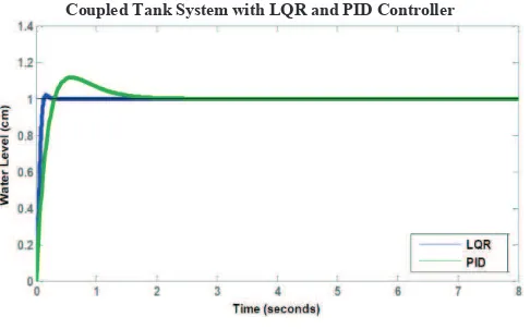
As mention earlier, the smaller the fitness value the better the system will be and it has been proven by the result of CTS with LQR and PID controller shown in Fig. 9. By comparing the result of fitness, LQR controller has smaller ITSE value compared to PID controller which led to better system performance. In this study only single objective is consider. Hence, better system performance indicates the overall transient response of CTS which is rise time, settling time, percentage overshoot and steady state error.
Coupled Tank System with LQR and PID Controller
Fig. 9. CTS Response using LQR and PID Control
By observation, it can be seen that CTS with LQR has better system performance compared to CTS with PID. In order to prove the observation, system performance data are taken and shown in Table 3. Based on the result, LQR controller gives less overshoot compared to PID controller. It’s also shown that using LQR as controller meets the steady state condition in short period of time. The results of transient response of the controller are also presented and shown in Fig. 10.
Table 3. System Performance of CTS
Response Controller
LQR PID
Rise Time, Tr (s) 0.0792 0.22
Settling Time, Ts (s) 0.1200 1.46
Overshoot, OS (%) 1.83 11.6
Steady-state Error 0 0
Fig. 10. Comparison of LQR and PID System Performance
By referring to Fig. 10, it is clearly shown that the transient response of LQR controller is better than PID controller. As for the rise time, LQR gives faster response with 0.1408s faster than PID. In terms of settling time, the time taken for LQR to settle is 0.12 s whereas PID is 1.46 s. LQR also shown better performance in term of overshoot, PID gives quite high overshoot reading which merely 11% while LQR has only 1.83%. Both controllers give zero steady state error.
VI. CONCLUSION
In this paper, a parameter tuning using PSO for LQR and PID controller is presented. The controller is implemented to Coupled Tank System for the purpose of comparing the controller performance. The study shows that both LQR and PID controller are successfully tuned with PSO and give good system performance which is proven with near ITSE result. In terms of performance, LQR gives better system performance compared to PID. The statement is supported with good overall transient response of LQR than PID.
ACKNOWLEDGMENT
The authors wish to thank Universiti Teknikal Malaysia Melaka (UTeM) and university short-term grant PJP/2013/FKE(7C)/S01178 for their financial support. This support is gratefully acknowledged.
REFERENCES
[1] M. Seyedkazemi, "Desiging Optimal PID controller with Genetic Algoritmn in View of Controller location in the Plant," Proceedings of the 7th WSEAS International Conference on Signal Processing, Robotics and Automation (ISPRA '08), p. 5, 2008.
Comparison of LQR and PID Controller Response
[2] M. A. A. A.N.K. Nasir, M.F. Rahmat, "Performance Comparison Between LQR and PID Controllers for an Inverted Pendulum System " in International Conference on Power Control And Optimization, Chiang Mai, Thailand, 2008.
[3] A. Mohammadbagher and M. Yaghoobi,
"Comparison Performance between PID and LQR Controller for 4-leg Voltage Source Inverter," in International Conference on Circuit, System and Simulation, 2011, pp. 230-234.
[4] A. S. M. Nor, H. Selamat, and A. J. Alimin, "Optimal Controller Design for a Railway Vehicle Suspension Sysytem using Particle Swarm Optimization," Jurnal Teknologi (Sains & Kejuruteraan), universiti teknologi Malaysia, vol. 54, p. 14, Jan 2011.
[5] S. Y. S. H. H.I Jaafar, N.A Selamat, M.S.M Aras, M.Z.A Rashid, "Development of PID Controller for Controlling Desired Level of Coupled Tank System," International Journal of Innovative Technology and Exploring Engineering (IJITEE), vol. 3, p. 5, Febuary 2014.
[6] R. Ditmar, S. Gill, H. Singh, and M. Darby, "Robust Optimization-based Multi Loop PID Controller Tuning: A New Tool and its Industrial Application," Control Engineering Practise, p. 16, 2012.
[7] T. Slavov and O. Roeva, "Application of Genetic Algoritmn to Tuning a PID controller for Glucose Concentration Control," WSEAS Transactions on System, vol. 11, p. 11, July 2012.
[8] L. B. Prasad, B.Tyagi, and H.O.Gupta, "Optimal Control of Nonlinear Inverted Pendulum Dynamical Sysytem with Disturbance Input using PID Controller and LQR " in IEEE Internasional Conference on Control System, Computing and Engineering, 2012, pp. 540-545.
[9] A. R. S. Mobayen, M. Moradi and B.
Mohammady, "Linear Quadratic Optimal Control System Design using Particle Swarm Optimization Algorithm," International Journal of the Physical Sciences, vol. 6, p. 9, 23 November 2011.
[10] N. A. W. N A Selamat, S Sahlan, "Particle Swarm Optimization for Multivariable PID Controller Tuning," in IEEE 9th International Colloquium on Signal Processing and its Applications, Kuala Lumpur, Malaysia, 2013, p. 6.