Abstract—The industrial application of Coupled Tank System (CTS) are widely used especially in chemical process industries. The overall process need liquids to be pumped, stored in the tank and pumped again to another tank for certain desired level. Nevertheless, the level of liquid in tank need to be controlled and flow between two tanks must be regulated. This paper presents development of Proportional-Integral-Derivative (PID) controller for controlling the desired liquid level of the CTS. Various conventional techniques of PID tuning method will be tested in order to obtain the PID controller parameters. Simulation is conducted within MATLAB environment to verify the performances of the system in terms of Rise Time (Ts), Settling Time (Ts), Steady State Error (SSE) and Overshoot (OS). Four techniques which are trial and error method, auto-tuning method, Ziegler-Nichols (Z-N) method and Cohen-Coon (C-C) method will be implemented and all the performance results will be analyzed. It has been demonstrated that performances of CTS can be improved with appropriate technique of PID tuning methods.
Index Terms— Coupled Tank System (CTS), PID Controller, PID Tuning Method, Water Level Control.
I. INTRODUCTION
Real time control involves algorithms to control a certain processes. In order to study the performance in terms of implementation in real time and each control features, control of level of a Coupled Tank System (CTS) is chosen. This application is widely used in the process industries especially in chemical industries [1]. It is often essential that the liquid to be supplied in tanks. It will be stored up in tanks and transferred it to the other tank as per requirement. The liquid must be maintained at a specific height or in a certain level. If the level cannot be maintained at the specific height as requirement, it can bring losses to the company or industries.
A common control problem in process industries is to control the fluids level in storage tanks and chemical blending. The flow of the liquid into and out the tank must be regulated as to achieve a constant desired liquid level as fluid to be supplied at a constant rate. This process are performing in closed loop condition because open loop is not practical and identification process more complicated especially in industrial production processes [2-3]. Closed loop process is very important due to safety or production restriction reasons [4].
Manuscript received February, 2014.
H.I. Jaafar, Faculty of Electrical Engineering (FKE), Universiti Teknikal Malaysia Melaka (UTeM), Hang Tuah Jaya, 76100 Durian Tunggal, Malaysia.
S.Y.S. Hussein, Faculty of Electrical Engineering (FKE), Universiti Teknikal Malaysia Melaka (UTeM).
N.A. Selamat, Faculty of Electrical Engineering (FKE), Universiti Teknikal Malaysia Melaka (UTeM).
M.S.M. Aras, Faculty of Electrical Engineering (FKE), Universiti Teknikal Malaysia Melaka (UTeM).
M.Z.A. Rashid, Faculty of Electrical Engineering (FKE), Universiti Teknikal Malaysia Melaka (UTeM).
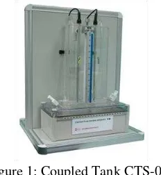
The Coupled Tank CTS-001 is a computer controlled CTS that is used for liquid level control as shown in Figure 1.
Figure 1: Coupled Tank CTS-001
The concept of virtual instrumentation is introduced in CTS-001. The need for traditional dedicated user interfaces on individual instrumentations can be eliminate by using virtual instrumentation techniques [5]. Besides, the computer can be used as the tool of communications between the hardware and software. Through the software analysis, it enables to carry out the function of oscillation and display the input and output response. From the system, it also can verify the parameter of the model which can be derived from the mathematical modeling [6-10]. This output response from the modeling function can be taken as the bench mark to achieve good response after implemented it in the CTS. The performance can be easily monitored in MATLAB simulation.
II. PID CONTROLLER
The industrial, CTS are widely used in consumer liquid proceeding and chemical processing industry. In order to control the level of the liquid, a conventional PID controller had been implemented. PID Controller is the most controllers that always been used in industrial control because of easy and simple to implement [11-15]. There are several methods to obtain the parameters for PID controllers such as trial and error method, Ziegler-Nichols (Z-N) method and Cohen-Coon (C-C) method. Tuning method is very important in control system. The values of the parameters in the controller can affect the performance of the system. The performance of the system can be generally improved by proper tuning but it also can be worsen the performance with poor tuning. In PID, there are several
tuning method that can
be used to find the desired control response.
A. Trial and Error
Try and Error is one of the method and easiest way to obtain the value of PID parameter. In this method, no mathematical is required. However, the optimal value of the parameter is not guaranteed. The value of KI and KD need to
be set first as zero before increasing the KP. This will takes a
lot of time and experience skill to obtain the best result.
Development of PID Controller for Controlling
Desired Level of Coupled Tank System
B. Ziegler-Nichols (Z-N)
Z-N is the tuning method that is widely used of tuning PID controller. It is developed by John G. Ziegler and Nanthaniel B. Nichols in 1940s [16]. In this tuning method, KI and KD
gain are also need to be set first to zero. Then KP is increased
until it reaches the ultimate gain, KU at which the output of
the loop starts to oscillate in the oscillation period, TU.
C. Cohen-Coon (C-C)
C-C tuning method is the second popular after the Z-N tuning method. The method was published by Cohen and Coon in 1953 [17]. This method is more flexible that Z-N tuning method in the wider variety of processes. Z-N method work well only on the processes where the dead time is less than half the length of the time response compared to the C-C method where the dead time is less than two times the length of the time constant.
III. MATHEMATICAL MODELING OF CTS
It is vital to understand the mathematics modeling of the behavior of Coupled Tank System (CTS). In this system, the nonlinear dynamic model is observed and the linearization process is done from the nonlinear model.
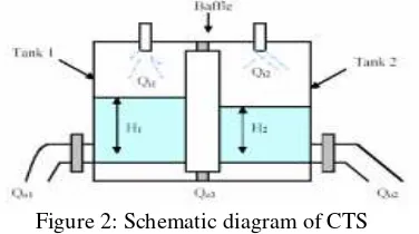
Figure 2: Schematic diagram of CTS
Based on Figure 2, H1 and H2 are the fluid level in Tank 1
and Tank 2. It is measured with respect to the corresponding outlet. Considering a simple mass balance, the rate of change of fluid volume in each tank equals the net flow of fluid into the tank. Therefore, the equation for Tank 1 and Tank 2 are:
3 Bernoulli’s equation for steady, non-viscous, incompressible shows that the outlet flow in each tank is proportional to the square root of the head of water in the tank. Similarly, the flow between the tanks is proportional to the square root of the head differential. Thus:
1
depend on the coefficients of discharge, the cross sectional area of each orifice and the gravitational constant. By substitute (3), (4) and (5) into (1) and (2), the nonlinear state equations which describe the system dynamics of the CTS
variable and q1 is the manipulated variable and assume that
q2 is zero.
The block diagram of the second-order system can be simplified as shown in Figure 3.
Figure 3: Block diagram of second order system
Thus, the nonlinear CTS can be obtained as:
The transfer function for the plant can be obtained by substituting the parameter which was provided from the [5]. The provided parameters are shown in Table 1.
Table 1: Parameter of CTS
Parameters Value Unit
H1 17 cm
H2 15 cm
α1 10.78 cm3/2/sec
α2 11.03 cm3/2/sec
α3 11.03 cm3/2/sec
A1 32 cm2
A2 32 cm
2
Then, all the parameters in Table 1 have been inserted into (8). Thus, the actual transfer function of the plant with the completed value is:
4514 . 0 1565 . 12 9406 . 36
0361 . 0
) (
) ( ) (
2 1
2
s s
s q
s h s
Gp
(15)
IV. RESULT AND DISCUSSION
The plant of the CTS is obtained from the mathematical modeling in previous section. The input voltage injected in the system is 1 Volt (V) and the level converter will convert the input voltage to the water level. For this case the desired level is 1 cm. The block diagram and the response of the system are shown in Figure 4.
Figure 4: Control structure with PID Controller
The stability of the system can be determined by Routh-Hurwitz stability criterion as in Table 2. It is a mathematical test that is a necessary and sufficient condition for the stability of a linear time invariant (LTI) control system. Table 2 shows the Routh-Hurwitz table for the transfer functions of the CTS as in (16) based on the characteristic equation.
0 0361 . 0 4514 . 0 16 . 12 94 .
6 s2 s K (16)
The system is determined as a stable system only if the coefficients in the first columns are all positives.
Table 2: Routh-Hurwitz table for CTS
s2 36.91 0.4514 +
0.0361K 0
s1 12.16 0 0
s0
K
K K
0361 . 0 4514 . 0
16 . 12
)] 0361 . 0 4514 . 0 ( 16 . 12 0 [
16 . 12
0 16
. 12
0361 . 0 4514 . 0 94 . 36
0 0
According to Table 2, CTS is stable because it can be proved that the coefficients in the first column are all positives sign.
s2 + 36.91
s1 + 36.91
s0 + [0.4514+0.0361K]
Table 3 shows the parameters of the PID controller (KP, KI
and KD). According to this table, the tuning method of PID
controller has shown the capability of the system by using either calculation approach or experiences approach.
Table 3: Parameter of PID Controller
Method
Parameter
KP KI KD
Trial and error 15.00 1.00 8.00
Auto-tuning 53.40 1.54 -2.98
Ziegler-Nichols 168.00 35.00 201.60
Cohen-Coon 235.88 33.92 203.21
Table 4 shows the summary of the transient response specification of the PID controller by the classical tuning method respect to the parameters of the controller.
Table 4: Performance of CTS
Method Ts
(sec)
Tr (sec)
OS (%)
SSE (cm)
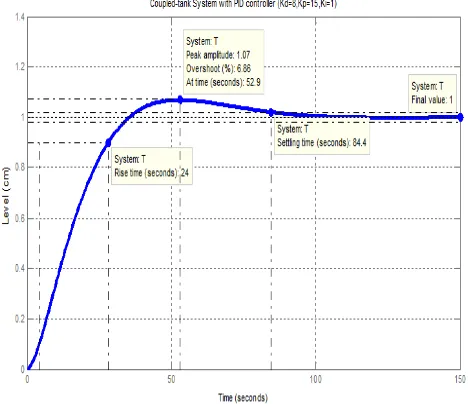
Trial and error 84.40 24.00 6.86 0.00 Auto-tuning 53.30 9.14 1.81 0.00 Ziegler-Nichols 32.10 3.29 38.50 0.00 Cohen-Coon 23.59 2.81 33.70 0.00
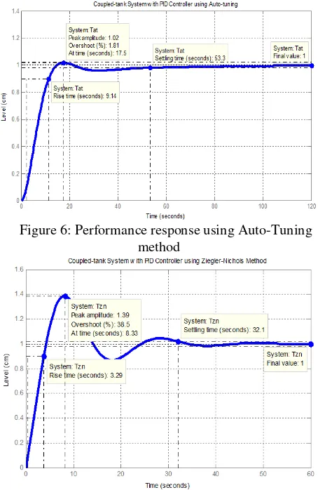
One of the transient response specifications which are settling time shows that C-C method had the fastest time for the system to reach the stable condition in the system. From the tuning method of Z-N, the response of the system is the second fastest after the C-C, compared to the other tuning method. Besides, C-C method shows that it has the fastest time in the rise time in the system followed by Z-N, auto-tuning and Trial and Error method. However, C-C method has the fastest time response for the system, but the percentage of the overshoot is higher compared to the others methods. Figure 5, 6, 7 and 8 are the performance for each method respectively.
Figure 6: Performance response using Auto-Tuning method
Figure 7: Performance response using Z-N method
Figure 8: Performance response using C-C method
In addition, Figure 9 summarizes all the results in graphical representation.
Figure 9: Response of CTS with various tuning method of PID controller
It can be concluded that by using the conventional tuning method for PID controller have their own advantages and disadvantages. For the trial and error method, it takes long time to achieve a good performance unless having enough experience to tune it. Then, it can save time. For the Z-N tuning method, it is the popular method in the industry. This method required short time to complete and easy to use than the other methods. Even though it is a popular method but through this method, it produced an aggressive gain and overshoot in the system. This method is similar to the C-C method. The process reaction curve is obtained first from the open-loop system before substituting the value in the standard recommended equation. The difference between Z-N method and C-C method is the parameters of Ti and Td can be obtained in open-loop and closed-loop system for Z-N method but for C-C method, the parameters can only be obtained in open-loop system. Last but not least, for the Auto-Tuning method, even though it is the simplest method but the value obtained from this method does not refer on the respective parameter. The value which is obtained from this method is the combination of the parameters in PID controller.
V. CONCLUSION
In order to control the level of the liquid, a conventional PID controller had been implemented. The parameter of the PID controller can be tuned by the traditional method such as trial and error, Z-N, C-C and auto-tuning. The performance of the system may achieve the good performance but quite difficult for finding the parameters. It required a lot of effort and experiences to obtain a good gain of the controllers. Therefore, optimization approach will be implemented to find the optimal parameters of the controller. By using this approach, a good gain and better performance is expected.
ACKNOWLEDGMENT
Authors would like to thanks Universiti Teknikal Malaysia Melaka (UTeM) for sponsoring this project. This project was conducted under the university short-term grant PJP/2013/FKE(7C)/S01178. Deep appreciations are also dedicated to anyone who directly or indirectly involved in this project.
REFERENCES
[1] M. F. Rahmat and S.M. Rozali, “Modelling and Controller Design for a Coupled-Tank Liquid Level System: Analysis & Comparison”, Journal of Technology, vol. 48 (D), June. 2008, pp. 113-141.
[2] Kealy, T. and O' Dwyer, A. “Comparison of Open and Closed Loop
Process Identification Techniques in the Time Domain”, Proc. of the 3rd
Wismarer Automatisierungs Symposium, Wismar, Germany, Sept. 2001, pp. 3-4.
[3] S. N. Basir, H. Selamat, H. Yussof, N. I. Zahari and S. Shamsuddin,
“Parameter Estimation of a Closed Loop Couple Tank Time Varying System using Recursive Methods”, IOP Conf. Series: Materials Science
and Engineering, vol. 53, Dec. 2013, pp. 1-10.
[4] Gilson, M. and Van Den Hof, P. “Instrumental Variable Methods for
Closed Loop System Identification”, Automatica, vol. 48 (2), Feb. 2005,
pp. 241-249.
[5] Coupled-Tank Liquid Level Computer-Controlled Laboratory Teaching Package: Experimental and Operation (Service) Manual, Augmented Innovation Sdn. Bhd., Kuala Lumpur, Malaysia
[6] N. Hasim, M. S. M. Aras, M. Z. A. Rashid, A. M. Kassim and S. S.
Abdullah, “Development of fuzzy logic water bath temperature controller using MATLAB,” 2012 IEEE International Conference on Control
[7] M. Z. A. Rashid, T. A. Izzuddin, N. Abas, N. Hasim, F. A. Azis and M. S.
M. Aras, “Control of Automatic Food Drive-Through System using
Programmable Logic Controller (PLC),” International Journal of U-& E-Service, Science & Technology, vol. 6 (4), 2013.
[8] M. Z. A. Rashid, M. S. M. Aras, H. N. M. Shah, W. T. Lim and Z.
Ibrahim, “Design and system parameter's validation of the unicycle mobile robot,” 2012 International Conference on Control, Automation and Information Sciences, 26-29 Nov. 2012, Vietnam, pp. 311-316. [9] M. Z. A. Rashid and S. N. Sidek, “Dynamic modeling and verification of
unicycle mobile robot system,” 2011 4th International Conference on
Mechatronics, 17-19 May 2011, Kuala Lumpur, Malaysia, pp 1-5. [10] M. S. M. Aras, S. N. S. Salim, Eric Chee Sai Hoo, and M. H. Hairi,
“Comparison of Fuzzy Control Rules Using MATLAB Toolbox and
Simulink for DC Induction Motor-Speed Control”, IEEE International Conference of Soft Computing and Pattern Recognition, 2009. SOCPAR'09, pp 711-715.
[11] M.S.M Aras, M.F. Basar, N. Hasim, M.N. Kamaruddin, and H.I. Jaafar,
“Development and Modeling of Water Tank System Using System Identification Method”, International Journal of Engineering and
Advanced Technology, Aug. 2013, pp. 278-283.
[12] N. A. Selamat, N. A. Wahab, and S. Sahlan, “Particle Swarm Optimization for Multivariable PID Controller Tuning”, 2013 IEEE 9th International Colloquium on Signal Processing and its Applications, 8 - 10 Mac. 2013, Kuala Lumpur, Malaysia, pp. 170-175.
[13] H. I. Jaafar, Z. Mohamed, J. J. Jamian, A. F. Z. Abidin, A. M. Kassim and
Z. A. Ghani, “Dynamic Behaviour of a Nonlinear Gantry Crane System,” Procedia Technology, vol. 11 (C), 2013, pp. 419-425.
[14] H. I. Jaafar, Z. Mohamed, A. F. Z. Abidin and Z. A. Ghani, “PSO-Tuned PID Controller for a Nonlinear Gantry Crane System,” 2012 IEEE International Conference on Control System, Computing and Engineering, 23-25 Nov. 2012, Penang, Malaysia, pp. 515-519. [15] H. I. Jaafar, M. F. Sulaima, Z. Mohamed and J. J. Jamian, “Optimal PID
Controller Parameters for Nonlinear Gantry Crane System via MOPSO Technique,” 2013 IEEE International Conference on Sustainable Utilization and Development in Engineering and Technology, 30 May – 1 June, 2013, pp. 86-91.
[16] J. G. Ziegler, and N. B. Nichols, “Optimum Setting for Automatic
Controllers”, Transactions of ASME, vol. 64, Nov. 1942, pp. 759-768. [17] G.H. Cohen and G.A. Coon, “Theoretical Consideration of Retarded
Control”, Transactions of ASME, vol. 75, 1953, pp. 827-834.
Hazriq Izzuan Jaafar received his B.Eng degree in Electrical Engineering from Universiti Teknologi Malaysia (UTM), in 2008. He received the M.Eng degree in Mechatronics and Automatic Control engineering also from UTM, in 2013. Currently, he is a Lecturer at Universiti Teknikal Malaysia Melaka (UTeM) and his interests are in control system and optimization techniques.
Sharifah Yuslinda Syed Hussien received her Diploma in Electrical Engineering from Universiti Teknikal Malaysia Melaka (UTeM), in 2011. Currently, she pursues her degree in Electrical Engineering in Control, Instrumentation and Automation System, UTeM.
Nurasmiza Selamat received his B.Eng degree in Electrical Engineering from Universiti Teknologi Malaysia (UTM), in 2009. She received the M.Eng degree in Mechatronics and Automatic Control engineering also from UTM, in 2013. Currently, she is a Lecturer at Universiti Teknikal Malaysia Melaka (UTeM) and her interests are in control system and optimization techniques.
Mohd Shahrieel Mohd Aras is a lecturer at Faculty of Electrical Engineering, Universiti Teknikal Malaysia Melaka UTeM. He currently pursues his PhD in Control and Automation, Faculty of Electrical Engineering, Universiti Teknology Malaysia. His current research is focusing on control system design of underwater technology. His primary interests related to nonlinear underwater robotics and Artificial Intelligence.
Mohd Zamzuri Ab. Rashid received his B.Eng degree in Mechatronics from International Islamic University in 2005. He finished his MSc. in Mechatronics from International Islamic University in 2012. Currently, he serves as lecturer in Universiti Teknikal Malaysia Melaka. His current research interests include unmanned system