i
IMPLEMENTATION OF PID CONTROLLER USING PSO AND HARMONY SEARCH ALGORITHM FOR DC MOTOR SPEED CONTROL SYSTEM
LEE KIAN LOONG
This Report Is Submitted In Partial Fulfillment Of Requirements For The Bachelor Degree Of Electronic Engineering (Industrial Electronics) With Honors
Fakulti Kejuruteraan Elektronik dan Kejuruteraan Komputer Universiti Teknikal Malayasia Melaka
ii
Tajuk Projek IMPLEMENTATION OF PID CONTROLLER USING PSO AND HARMONY SEARCH ALGORITHM FOR DC
MOTOR SPEED CONTROL SYSTEM
Sesi
Pengajian 1 4 / 1 5
1.
Saya LEE KIAN LOONG mengaku membenarkan Laporan Projek Sarjana Muda ini disimpan di Perpustakaan dengan syarat-syarat kegunaan seperti berikut:
1. Laporan adalah hakmilik Universiti Teknikal Malaysia Melaka.
2. Perpustakaan dibenarkan membuat salinan untuk tujuan pengajian sahaja.
3. Perpustakaan dibenarkan membuat salinan laporan ini sebagai bahan pertukaran antara institusi pengajian tinggi.
4. Sila tandakan ( √ ) :
SULIT*
*(Mengandungi maklumat yang berdarjah keselamatan atau kepentingan Malaysia seperti yang termaktub di dalam AKTA RAHSIA RASMI 1972)
iii
iv
“I hereby declare that I have read this report and in my opinion it is satisfied in partial fulfillment of requirements for the Bachelor of Electronic Engineering with (Industrial
v
vi
ACKNOWLEDGEMENT
vii
ABSTRACT
Nowadays the DC motor is common used in industrial application. However, the performance of DC motor without any controller is unstable due to high overshoot, rise time, settling time and steady-state error. Therefore, the PID controller will be implemented into the DC motor system to solve those problems. This project focused on the tuning method for the parameter of PID controller such as PSO algorithm and Harmony Search Algorithm. These algorithms will help to obtain the optimization value of PID parameters. Therefore, the optimization value of PID parameters can decrease the maximum overshoot, shorter rise time, settling time and the steady-state error. This improvement will cause the performance of the DC motor more stable and function well.
viii
ABSTRACT
ix
Algorithm Based PID Controller 5-6
2.2.2 Simulation of Optimal Speed Control for a DC Motor Using Conventional PID Controller and Fuzzy Logic Controller
6-7
1.2.2 2.2.3 Speed Control of DC Motor using PID Controller Based on Matlab
x
1.2.3 2.2.4 Real Time DC Motor Speed Control using PID Controller in LabVIEW
9
1.2.4 2.2.5 DC Motor Speed Control : A Case between PID Controller and Fuzzy Logic Controller
9-10
1.2.5 2.26 Performance Based Comparison Between Various Z-N Tuning PID And Fuzzy Logic Controller In Position Control System of DC Motor
10-11 Alteration Parameters Using Particle Swarm Optimization Strategy
12-13
1.2.9 2.3.3 Optimal Tuning of PID Controller Parameters on a DC Motor Based on Advanced Particle Swarm Optimization Algorithm
13
1.2.10 2.3.4 Automatic Tuning of Proportional-Integral-Derivative (PID) Controller Using Particle Swarm Optimization (PSO) Algorithm
14
1.2.11 2.3.5 Optimal Tuning of PID Controller using Adaptive Hybrid Particle Swarm Optimization Algorithm
14
1.2.12 2.3.6 Analysis of Particle Swarm Optimization Algorithm
14-15
2.4 Harmony Search Algorithm 15-20
1.2.13 2.4.1 A Harmony Search with Adaptive Pitch Adjustment for Continuous Optimization
xi
1.2.14 2.4.2 The variants of the harmony search algorithm 16-17 1.2.15 2.4.3 Tetris Agent Optimization Using Harmony
Search Algorithm
III PROJECT METHODOLOGY 21-22
3.1 Project Planning 23-24
3.2 Software Implementation 25
3.3.1 Simulink 25
3.3.2 Matlab 28
3.3 Transfer Function of DC motor 25-28
3.3.1 Real experiment (EMECS) 25-26
3.3.2 System identification approach 26-28
3.4 Block Diagram of DC Motor 28-29
3.5 PID Controller 29
3.6 Good gain method 30
3.7 Ziegler-Nichols Method 30
3.8 Particle Swarm Optimization(PSO) Algorithm 31 3.9 Harmony Search Algorithm (HSA) 31
IV RESULT AND DISCUSSION 32-46
4.1 System without any controller 32-33
4.2 Implementation PID controller into the system 33
4.2.1 Good Gain Method 34
4.2.2 Ziegler-Nichols Method 34-35
xii
4.3 Discussion 46
V CONCLUSION AND RECOMMENDATIONS 47-48
5.1 Conclusion 47
5.2 Recommendations 47-48
xiii
LIST OF TABLES
NO TITLE PAGE
1 The effect by using different values of derivative gain 8 2 Comparison of performance by using different tuning methods 11
3 Performance by using different tuning methods 11
4 The performance by using Fuzzy-PSO and PID-PSO controller 13
5 Advantage and disadvantage for PSO algorithm 15
6 The comparison results of distribution network planning for some
optimization algorithm 20
7 Formula for Z-N method 30
8 Performance for different number of particle using PSO algorithm 37 Performance for different number of iteration using PSO algorithm 38 9 Performance for different number of iteration and particle using
PSO algorithm 39
10 Performance for different number of iteration using HSA 41 11 Performance for different harmony memory using HSA 42
12 The result for different number of range 43
xiv
LIST OF FIGURES
NO TITLE PAGE
1 Schematic representation of DC motor 3
2 Block diagram for DC motor 4
3 Close loop system with PID controller 5
4 Block diagram for PID controller 7
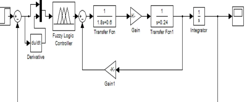
5 Block diagram for Fuzzy logic controller 7
6 The output response of DC motor 12
7 The harmony search optimization process 18
8 Block diagram of PID controller with the DC motor 26
9 DC motor with load 26
10 Sample block diagram of DC motor 29
11 Implementation of PID controller into the system 29
12 Way to calculate Tou 30
13 Block diagram for system 32
14 Output response of system 33
15 Block diagram for PID controller with the system 33 16 The output response for PID controller in the system 34
17 Output response for Ziegler-Nichols method 35
18 Circuit for tuning PID parameters using Matlab coding 36
19 Output response for PSO Algorithm 36
20 Output response for different number of particle 37 21 Output response for different number of iteration 38 22 Output response for different number of iteration and particle 39 23 Output response for Harmonic Search Algorithm 40 24 Output response for different number of iteration 41 25 Output response for different number of harmony memory 42 26 Output response for difference number of range 43 27 Comparison of output response for different type of tuning
methods 45
1
CHAPTER 1
INTRODUCTION
1.1 Overview
2
1.2 Problem Statement
1. Unknown plant or mathematical model of the system.
2. Undesired output response of the DC motor which used as adjustable or variables speed applications.
1.3 Objectives
1. To determine the mathematic model of the DC motor using system identification approach based on Real-Time workshop.
2. To design a PID controller for the purpose of controlling the speed of DC motor.
3. To apply PSO and Harmony Search Algorithm in PID controller for the purpose of tuning the PID parameters
4. To make a comparison and justification based on the controller performances obtained from the simulation.
1.4 Scope of Work
This project mainly focus on software design in Matlab / Simulink for overcome the problems like overshoot, high rise time ,tr high settling time ,ts and
3
CHAPTER 2
LITERATURE REVIEW
2.1 DC Motor System
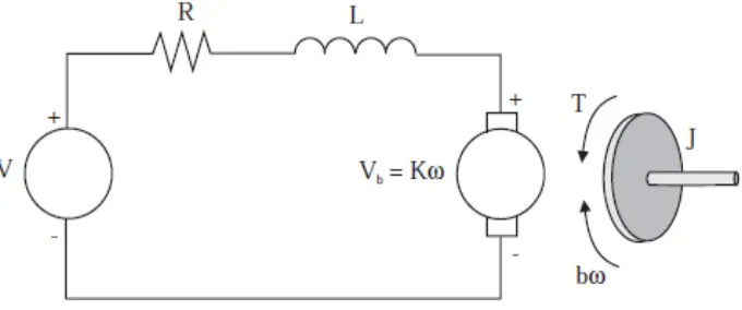
According to Jalilvand, A. Kimiyaghalam, A. Ashouri, H. Kord (2011), the design of block diagram for DC motor in the Simulink software will based on the transfer function that obtain from the Figure 2.1.
Figure 2.1: Schematic representation of DC motor
Using the Newton’s law combine with the Kirchhoff’s law,
(2.1)
4
Using the laplace transform for equation (2.1) and (2.2),
Js2 + bs = KI(s) (2.3)
LsI(s) + RI(s) = V(s) - Ks (2.4)
From the equation (2.4)
I (s) = (2.5)
Hence substitute equation (2.5) into (2.3)
Js2 + bs = K
(2.6)
Therefore the transfer function will be
(2.7)
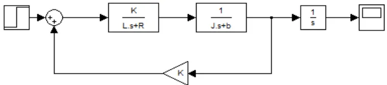
The block diagram for DC motor will construct as Figure 2.2 by using the transfer function that obtained from the schematic representation of DC motor.
5
2.2 PID Controller
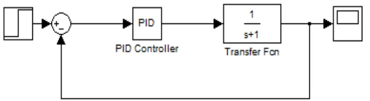
The purpose of implement PID controller into the system is to improve the dynamic response and reduce the steady-state error. The Figure 2.3 show how to implement the PID controller into the system in Simulink. There is a lot of other journal that research on the topic of PID controller and the comparison with other controller to observe the performance of the DC motor.
Figure 2.3 : Close loop system with PID controller
2.2.1 Speed Control of DC Motor Using Genetic Algorithm Based PID Controller
6
overshoot, rise time, settling time and steady-state error. The performance of DC motor will become not stable and accurate due to these problems.
After that, PID controller block diagram is inserted into system and then simulate the circuit to observe the output response. The output response with and without the genetic algorithm will be compared. Hence, the output response for the system with the genetic algorithm shows that it will eliminate the maximum overshoot problem. Besides that, it also reduces the rise time and settling time for the whole system. The steady-state error for the system with and without the genetic algorithm is almost zero percentage. Therefore, system with the genetic algorithm is much better performance for the system without the genetic algorithm due to overall characteristics.
2.2.2 Simulation of Optimal Speed Control for a DC Motor Using Conventional PID Controller and Fuzzy Logic Controller
Ritu Soni, DBV Singh, Pramod Pandey and Priyanka Sharma (2013) research about the comparison between the fuzzy logic controller and PID controller for speed control of DC motor. DC motor is the best choice for speed and position control in industrial applications. PID controller or the Fuzzy logic controller will normally implement with the DC motor to improve the performance and stability of the motor. Ziegler-Nichols frequency response and hand-tuning method will be used for tuning the parameter of the controller. These two methods can obtain the perfect output response but it requires a long period for tuning the parameters.
7
system is stable due to zero steady-state error from the simulation result. In conclusion, the performance of system with fuzzy logic controller is much better than system with PID controller due to overall characteristics. Therefore, Fuzzy logic controller is more suitable to implement into the DC motor system.
Figure 2.4: Block diagram for PID controller
8
2.2.3 Speed Control of DC Motor using PID Controller Based on Matlab
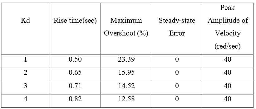
According to the Aditya Pratap Singh, Udit Narayan and Akash Verma (2013) , their research is designed the PID controller to control the speed response of the DC motor. Different value of PID parameters which is proportional gain, Kp integral gain, Ki and derivative gain, Kd will provide different effect to the performance of the DC motor. Table 2.1 show the effect of DC motor by using different values of Kd. Table 2.1 prove the value of rise time will increase but the value of maximum overshoot will decrease by increasing the value of Kd.
Table 2.1 : The effect by using different values of derivative gain
Kd Rise time(sec) Maximum
Hence, the values of Kp and Ki will be increased respectively to observe the effect to the performance of DC motor. From the observation of this research, increasing the value of Kp will cause the effect of decreasing the rise time and the steady-state error while increasing the value of Ki will cause the effect of eliminate the steady-state error and reducing the rise time. Therefore, different value of PID parameters will have the different effect to the performance of DC motor.
2.2.4 Real Time DC Motor Speed Control using PID Controller in LabVIEW
9
for low cost data acquisition board. The speed of the DC motor will sense by the tachometer that is a sensor to measure the revolution of the DC motor. The block diagram of closed-loop system for this system will design and simulate. It will connect with Arduino so that it can check the result taken from the tachometer in Arduino and the output response from Simulink is same or not. PID controller will make the speed of DC motor to become desired speed if the result taken from Arduino and Simulink is not the same.
2.2.5 DC Motor Speed Control : A Case between PID Controller and Fuzzy Logic Controller
Research of Philip A. Adewuyi(2013) is to make the comparison between the performance of Fuzzy logic controller and PID controller by using the block diagram in Simulink. The transfer function that used in this research is . Then, this transfer function will simulate in Simulink to observe the output response without any controller. In the result, the output response shows the rise time, settling time and the steady-state error is quite high. Therefore, PID controller and Fuzzy logic controller will be implemented to solve these problems.
The problem for using the PID controller is the unknown value for the proportional gain Kp, integral gain Ki and derivative gain Kd. Therefore, few methods such as trail and error method and Ziegler-Nichols method will use for tuning the parameter of the controller. Trial and error method will not consider because this method is waste time and might damage the DC motor. Hence, Ziegler-Nichols method will be the best choice for tuning the PID parameter.
10
Therefore, PID controller will more suitable to implement into the DC motor compare with Fuzzy logic controller although Fuzzy logic controller did not require any tuning method.
2.2.6 Performance Based Comparison Between Various Z-N Tuning PID And Fuzzy Logic Controller In Position Control System of DC Motor
G.SUDHA and DR.R.ANITA (2012) developed the design to make the comparison between the output response of the Fuzzy logic controller and the PID controller. The purpose of this research is to check which controllers can provide better performance of the DC motor. The transfer function of DC motor for this research is . The output response of the DC motor by using this transfer function will cause the performance of system is unstable. Therefore, others controller such as PID controller and Fuzzy logic controller will be implemented to improve the performance of the DC motor.