“I hereby declared that this report is a result of my own work except for the excerpts that have been cited clearly in the references.”
Signature : ………
Name : ROZITA BINTI JAMALUDIN
Signature : ……….. Supervisor’s Name : MR. SYED NAJIB BIN SYED SALIM
Submitted By:
ROZITA BINTI JAMALUDIN
This Report is Submitted in Partial Fulfillment of Requirements for the Degree of Bachelor of Electrical Engineering
(Control, Instrumentation and Automation)
FACULTY OF ELECTRICAL ENGINEERING UNIVERSITI TEKNIKAL MALAYSIA MELAKA (UTeM)
ACKNOWLEDGEMENT
First of all, I would like to express my thankfulness and gratitude to Allah S.W.T who has given me all the strength that I needed to prepare this report.
With this opportunity, I would like to express my gratitude to the Faculty of Electrical Engineering (FKE), Universiti Teknikal Malaysia Melaka (UTeM) generally, and especially to my supervisor Mr. Syed Najib b. Syed Salim for him helps, advices and guidance that he gave during this project.
And also to my parents, a million of thanks to them because of their support to me with their prayer and their love. Last but no least, I would like to thank all my friends 4BEKC whom have been such wonderful friends to me and also to everyone who was involved in the completion of this project. I would like to thank them for all support and encouragement to me which have given me the courage and wisdom to fulfill my report.
ABSTRACT
ABSTRAK
TABLE OF CONTENTS
CHAPTER TITLE PAGE
SUPERVISOR DECLARATION
DECLARATION i
DEDICATION ii
ACKNOWLEDGEMENT iii
ABSRACT iv
ABSRAK v
TABLE OF CONTENTS vi
LIST OF TABLES ix
LIST OF FIGURES x
LIST OF ABBREVIATIONS xii
1 INTRODUCTION
1.1 Background of the Project 1
1.2 The Concept of the Project 3
1.3 The Objectives of the Project 4
1.4 The Scope of the Project 4
1.5 Problems Statement 5
2 LITERATURE REVIEW
2.3 Types of Control System 11
2.3.1 PID Controller 11
2.3.1.1 Analog PID Controller 12
2.3.1.2 Digital PID Controller 13 2.3.1.3 Comparison Analog &
Digital PID Controller 14 2.3.2 Fuzzy Logic Controller 15
2.4 DC Motor Drives 17
2.5 Conference Paper Comparison 20
2.6 Components 21
2.6.1 Microcontroller 21
2.6.2 RS232 Circuit 22
2.6.3 LMD18200 H-Bridge 23
2.6.4 Potentiometer 24
3 METHODOLOGY
3.1 Overview 25
3.2 Project Components 28
3.2.1 Microcontroller PIC16F877A 28 3.2.1.1 Programming the
Microcontroller 30
3.2.1.2 PIC16F877A Burning
Process 30
3.2.2 Level Converter 32
3.2.3 The Plant 33
3.2.3.1 The Disk 33
3.2.3.2 Potentiometer 34
3.2.4 H-Bridge LMD18200 35
3.4 Hardware Implementation 38
4 RESULTS AND DISCUSSION
4.1 DC Motor Modeling 39
4.1.1 Transfer Function Result 39
4.1.2 State Space Result 40
4.2 PID Design Results 41
4.2.1 Proportional Control Result 41
4.3 PID Control Design 43
4.3.1 PI Controller 43
4.3.2 Tuning the Gain 44
4.3.3 Discussion 46
4.4 The Hardware Configuration 47
4.4.1 The Microcontroller Circuit 47 4.4.2 The Plant Configuration 47
4.5 Conclusion 48
5 CONCLUSION
5.1 Conclusion 49
5.2 Suggestion and Recommendation 50
REFERENCES 51
NO. TITLE PAGE
2.1 History of Control System 6
2.2 Choosing a Tuning Method 12
2.3 Components of Fuzzy Logic Controller 16
2.4 Conference Paper Comparison 20
NO. FIGURES PAGE
1.1 The Concept of the Project 2
2.1 Simplified Description of Control System 7
2.2 Dynamic Response of Control System 7
2.3 Closed-Loop Position/Speed DC Servo Motor 8
2.4 Open-loop System 9
2.5 Closed-loop System 10
2.6 Block Diagram of Analog PID Controller 13
2.7 Block Diagram of Digital PID Controller 14
2.8 Block of Fuzzy Controller 15
2.9 DC Motor 17
2.10 DC Motor Operation 18
2.11 PIC16F877A 21
2.12 Connection Diagram of MAX232 22
2.13 LMD18200 23
2.14 Potentiometer 24
3.1 Methodology of Project 26
3.2 Crystal Oscillator and Capacitor Circuit Diagram 29
3.3 Voltage Regulator Connection Diagram 29
3.4 Multi PIC JDM Programmer 31
3.5 RS232 Circuit 32
3.6 The Disk 33
3.7 The Potentiometer 34
3.8 Functional Block Diagram of LMD18200 35
4.1 Transfer Function Step Response 40
4.2 State Space Step Response 40
4.3 Proportional Control Step Response 41
4.4 Step Disturbance Response 42
4.5 Step Response of PI Controller 43
4.6 Step Disturbance Response of PI Controller 44
4.7 Step Response of Tuning the Gain 44
4.8 Step Disturbance Response of Tuning the Gain 45
4.9 Step Response of PID Controller 45
4.10 The Circuit Board 47
AC Alternating Current
ADC Analog-to-Digital Converter
C Capacitor
DAQ Data Acquisition System
DC Direct Current
EMF Electromagnetic Force
K Gain
PC Personnel Computer
PCB Printed Circuit Board
PID Proportional-Integrated-Derivative PWM Pulse Width Modulation
SP Set Point
Ts Settling Time
Tp Peak Time
CHAPTER 1
INTRODUCTION
The “Real Time PID Position Controlled DC Motor Drives” project is designed
to develop a firmware (hardware and software). The purpose of this project is to apply
the theory of PID control system to real implementation and analyze the operation of
PID controller for DC motor position control application. In addition, this project covers
the software programming and hardware configuration to get the output response. This
chapter will discuss about the background of the project, the concept of the control
system, the concept of the project, the objectives, the scope of the project, and problem
statement.
1.1 BACKGROUND OF THE PROJECT
The motion control is the position and/or velocity of configuration by controlled
using some type of device such as a hydraulic pump, linear actuator, or motor drives
generally a servo. For this project, the device that uses to control position is DC motor
drives because servo motion control is reliable option for providing advanced
positioning performance. Moreover, DC motor is relatively simple and eases to control
the system.
will give difficulty to students to study concept control system with profounder. This
project can gives opportunity to student to study and understand real idea of control
system. This project is a simple application to see the motion of plant which it controls
by the controller. So, it can facilitate for student especially to more understand about the
control system. Furthermore, more sophisticated technology in electronic field current
makes control system more complicated.
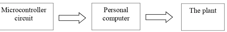
1.2 THE CONCEPT OF THE PROJECT
The overall concept for this project can be illustrated as shown in Figure 1.1
below. The PIC16F877A circuit board gives the directive via the program in microC to
give the program for microcontroller. Then the personal computer gives the direction
and position command via Visual Basic 6.0. Then the plant will move followed the
instruction that given.
Figure 1.2: The concept of the project Microcontroller
circuit
Personal computer
The main objective of this project is to develop the controller for position
controlled of DC motor using PID controller. This project required to design and builds
a functional hardware and designs a control system program for the controller.
Indirectly, this project enable students understand characteristics of PID controller and
facilitate learning process. The objectives of this project are:
i. To perform a modeling DC motor.
ii. To develop the operation of PID controller for DC motor position control
application.
iii. To analyze the performances of DC motor with different position.
iv. To display the result obtained via Microsoft Visual Basic 6.0.
1.4 THE SCOPE OF THE PROJECT
The scope of this project is to present an inventive design related to learning
control system application for use in teaching process. In order to present this design, the
project comprise of a circuit board related to the block appearing on the block diagram
of a control system. This project has a control circuit and display the output response of
the controllers.
This project has the implementation of hardware and software which we can
more understand for this application. This project has a control circuit which using
PIC16F877A as controller. Then, the plant will convert the signal from MicroC
programming to personal computer. The output response will display via Microsoft
Visual Basic. The hardware is the DC motor known as the circuit board and the plant.
In industry, PID controller is the widest kind of automatic control. It is because
PID Controller is the comparatively simple structure and slight variations to be relevant
in industry. The theoretical and the real application must be related to make the learning
process easy to understand and can show the theory and practical. The main problem is
to present the PID controller in control system particularly to transform theoretical in the
form of a real time application. Therefore, to take in hand this problem, we will need
more understanding in control system basic and practical.
This project is the best solution to apply the theory of the control system that
learned in lecture to real implementation. Theoretically, the PID controller is a system
which has calculation and rules. Hence, the students are difficult to understand fully the
concept of control system. By such, this project can implement the concept of control
system to the real configuration. By doing this project can help the students to
understand the characteristics of PID controller in control system. The characteristics of
PID controller in control system are performing in real time.
CHAPTER 2
LITERATURE REVIEW
This chapter will discuss about the important concept of control system and
analysis described in “Real Time PID Position Controlled DC Motor Drives” project.
There is the information concern control system, PID controller and the DC motor
control. The research of literature review is to give explanation theoretically which
related in this project and describe the currency of system project.
2.1 HISTORY OF CONTROL SYSTEM
Control system was existed before evolution of humanity and started essentially
in the ancient world. Human realize about existence of the control system when they
know that control system can improve and help them to facilitate and easiness their
routine live. Therefore, many biological control systems were built into the earlier
residents of our earth.
Many members’ sciencetist ancient times do various experiments and test study
for get correct theory on control system. Various improvements also are done by
sciencetist so that they get correct conclusion and can use by next generation. The
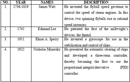
The table below is about briefly history of control system.
Table 2.1: History of control system
NO. YEAR NAMES DESCRIPTION
1. 1736-1819 James Watt He invented the flyball speed governor to
control the speed of steam engines. In this
device, two spinning flyballs rise as rational
speed increases.
2. 1745 Edmund Lee He patented the first of the millwright’s
devices, the fantail.
3. 1911 Elmer A. Sperry He invented a gyroscope for use in the
stabilization and control of ships.
4. 1922 Nicholas Minorsky He presented the automatic steering of ships
and developed a three-term controller,
thereby becoming the first to use the
proportional-integral-derivative (PID)
controller.
Modern society has sophisticated control systems which are crucial to their
successful operation. Existence control system is based on several reasons which control
system very important in our live. The reasons are power amplification, remote control,
convenience of input form and compensation for disturbance. From definition, control
system is a device or a collection of devices that control the behavior of other devices.
The system can be controlled and adjusted the desired input response to give a
difference output response. But some devices are not controllable. A control system is
also connection of components or related components to describe the behaviors of the
system. We cannot see the behavior of the control system with roughly eye but with
have implement the control system to configuration to know the characteristics and
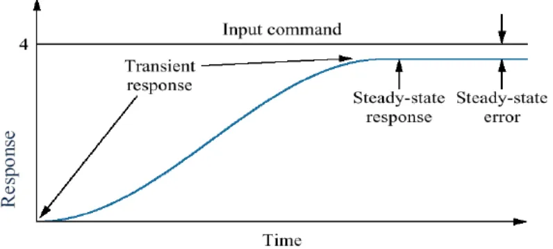
2.2 shows the dynamics response of a control system.
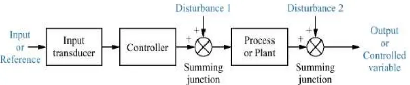
Figure 2.1: Simplified description of a control system
The control system receive the desired input response to give an output response
[image:22.612.131.529.321.500.2]which known as actual response.
Figure 2.2: Dynamic Response of Control System
The response will changes increasable until reach a steady-state response which
this point is critical point. The changes of response are called transient response until the
point of steady-state response. The differences of input command and the steady-state
response is known as steady-sate error. The differences value of gain will make the
steady-state error also change.
controller. An open-loop controller or a non-feedback controller is a type of controller
which computes its input into a system using only the current state and its model of the
system. A characteristic of the open-loop controller is that it does not use feedback to
determine if its input has achieved the desired goal. This means that the system does not
observe the output of the processes that it is controlling. Consequently, a true open-loop
system can not engage in machine learning and also cannot correct any errors that it
could make while closed-loop control systems typically operate at a fixed frequency.
When the frequency is changes to the drive signal, the sampling rate is also changes and
certainly not any faster.
A closed-loop control system is a feedback controller which the ability to reduce
the system stability. A closed loop control system is not like the open loop control
system which the changes of the errors will give inaccurate output. The one of
characteristics of control system is the transient response can adjusted until satisfactory.
If the open loop control system does not provide a satisfactory response, the process
must be replaced or modified. But in closed-loop control system can adjusted the desired
response by adjusting the feedback loop parameters. Many control system have
extraneous disturbances signals which provide inaccurate output, with have feedback
systems, the distortions or unwanted disturbances can be reduces.
Figure 2.3: Closed-loop position/speed DC servo motor
to some devices to perform a certain action and accomplishment. The actions that
perform are output response outcome from control system. Briefly, open-loop control
system does not have a feedback loop. It means the open-loop control system does not
continuously update its input and thus is not self-correcting. An open-loop control
system is controlled directly from an input signal because there no feedbacks loop. The
basic units of the open loop control system type consist only of an amplifier and a motor.
The amplifier receives a low- level input signal and amplifies it enough to drive the
motor to perform the desired job. The controller receives the input from input transducer
and the output response will perform via the plant. The plant is to display the output
response because control system is abstract to understand behaviors or characteristics of
control system without the plant.
Figure 2.4: Open-loop system