MODELING AND SIMULATION OF DIRECT TORQUE CONTROL OF BRUSHLESS DC MOTOR DRIVES
SAIDATINA AISHAH BINTI MOHD SHAH
B011010160
Bachelor of Electrical Engineering
(Power Electronic And Drives)
MODELING AND SIMULATION OF DIRECT TORQUE CONTROL OF BRUSHLESS DC MOTOR DRIVES
SAIDATINA AISHAH BT MOHD SHAH
A report submitted in partial fulfillment of the requirements for the degree of Electrical Engineering
Faculty of Electrical Engineering UNIVERSITI TEKNIKAL MALAYSIA MELAKA
DECLARATION
I declared that this report entitle “Modeling and Simulation of Direct Torque Control of
Brushless DC Motor Drives” is the result of my own research except as cited in the references.
The report has not been accepted for any degree and is not concurrently submitted in
candidature of any other degree.
Signature : ………..
Name : ………..
SUPERVISOR ENDORSEMENT
“I hereby declared that I have read through this report entitled “Modeling and Simulation of
Direct Torque Control of Brushless DC Motor Drives” and found that it has comply the partial
fulfillment for awarding the degree of Bachelor of Electrical Engineering (Power Electronic and Drives)”
Supervisor’s Signature : ………..
Supervisor’s Name : ………..
DEDICATION
i
ACKNOWLEDGEMENT
In the name of ALLAH, Most Generous and Most Merciful. With the deepest sense of
gratitude to ALLAH the Almighty for giving me strength and ability to complete this final
year project report. These special thanks goes to my supervisor namely Dr Auzani Bin Jidin
for his cooperation and advice that really help me to understand about my topic.
I would like to grab this chance to express my appreciation and thanks to my friends
who have shared some knowledge to me in the completion of this report. Their entire
companion is truly appreciated as it was a great pleasure to know them.
In addition, I would like to express my gratitude to my family members especially my
beloved parents for their morale support throughout the entire process of finishing this report.
Last but not least, I would like to thank each and everyone who has helped me directly or
ii
ABSTRACT
Direct Torque Control (DTC) operates in two-phase conduction mode; where only
two-phase produce switching at one time while the switching in conventional Torque
Hysteresis Controller (THC) method resulted in three-phase. Thus, the significant of study is
to prove that the switching frequency in THC is lower than DTC for every speed operating
ranges. The problem in THC method is poor torque regulation performance due to the current
or torque ripple is not restricted within predefined hysteresis bandwidth. As for DTC, the
problem occur when small hysteresis bandwidth produce high switching frequency than THC
in order to minimize torque ripple. This research project aims to model and simulate the DTC
of BLDC and make comparison between the switching frequency and torque/current control
performances produced in DTC and THC of BLDC drive. This simulation is conducted by
using Matlab/ Simulink. The first things to look at are the mathematical modeling of BLDC
motor. The anatomy of motor is required to understand basic operation of BLDC motor drive.
Besides, principle of DTC and theory about THC are also important in order to analyze the
performance of DTC and THC. The outcomes resulted from the simulation shows that DTC
have better torque regulation due to optimum voltage vector selection but higher switching
frequency than THC. As for the conventional THC, it produces poor torque regulation
performance and low switching frequency than DTC. It is proved that both THC and DTC
iii
ABSTRAK
Kawalan Terus Daya Kilas (DTC) beroperasi dalam mod pengaliran dua- fasa; di mana
hanya dua- fasa menghasilkan arus pada satu masa manakala pensuisan dalam konvensional
Tork Histeresis Controller ( THC) menghasilkan tiga fasa. Oleh itu, kepentingan kajian adalah
untuk membuktikan bahawa kekerapan pensuisan dalam THC adalah lebih rendah daripada
DTC bagi setiap kelajuan julat operasi. Masalah dalam kaedah THC adalah semakin prestasi
peraturan tork kerana riak semasa atau tork tidak terhad dalam ditentukan histerisis bandwidth.
Bagi DTC, masalah berlaku apabila jalur lebar histerisis kecil menghasilkan frekuensi
pensuisan tinggi daripada THC untuk mengurangkan tork riak. Projek penyelidikan ini
bertujuan untuk menjadi dan mensimulasikan DTC daripada BLDC dan membuat
perbandingan antara kekerapan switching dan persembahan kawalan tork / semasa dihasilkan
di DTC dan THC pemacu BLDC. Simulasi ini dijalankan dengan menggunakan Matlab /
Simulink . Perkara pertama yang perlu dilihatt adalah model matematik BLDC motor.
Anatomi motor diperlukan untuk memahami operasi asas BLDC memandu motor. Selain itu,
prinsip DTC dan teori mengenai THC juga penting untuk menganalisis prestasi DTC dan
THC. Hasil daripada simulasi menunjukkan bahawa DTC mempunyai peraturan tork yang
lebih baik tetapi kekerapan suis lebih tinggi daripada THC. Bagi THC konvensional, ia
menghasilkan prestasi yang lemah peraturan tork dan frekuensi pensuisan rendah daripada
DTC. Ia membuktikan bahawa kedua-dua THC dan DTC mempunyai kelebihan dan
iv
TABLE OF CONTENTS
ACKNOWLEDGEMENT i
ABSTRACT ii
ABSTRAK iii
TABLE OF CONTENTS iv
LIST OF FIGURE vii
LIST OF TABLE ix
LIST OF ABBREVIATIONS x
LIST OF APPENDICES xi
CHAPTER 1 1
INTRODUCTION 1
1.1 Overview 1
1.2 Significant of Research 5
1.3 Problem Statement 6
1.4 Objective 8
1.5 Scope of Research 8
1.6 Research Methodology 8
1.6.1 Flowchart 9
v
1.7 Report Outline 12
CHAPTER 2 13
LITERATURE REVIEW 13
2.1 Introduction 13
2.2 Torque Hysteresis Controller 13
2.3 Basic DTC method for Induction Motor 15
2.3.1.1 Basic Control Scheme of DTC of Induction Motor 19
2.3.1.2 Torque and Flux Control in DTC of Induction Motor 24
2.4 Related Previous Work 26
2.4.1 Variations of DTC methods in Two-Phase Conduction Mode for BLDC motor
26
2.5 Summary of Review 29
CHAPTER 3 30
METHODOLOGY 30
3.1 Introduction 30
3.2 Anatomy of BLDC 30
3.2.1 Sensored BLDC Control using Hall Effect Sensor 32
3.3 Mathematical Modeling of BLDC motor 40
vi
3.4.1 Control of Electromagnetic Torque by Selecting Proper Voltage Space Vector
49
3.4.2 Structure of DTC of BLDC 51
3.4.2.1 Simulation Model of DTC and THC of BLDC Motor 51
CHAPTER 4 55
RESULTS AND DISCUSSION 55
4.1 Simulation Results and Discussion 55
4.2 Overall Discussion 64
CHAPTER 5 67
CONCLUSION AND RECCOMENDATION 67
5.1 Conclusion 67
5.2 Recommendation 68
REFERENCES 70
vii
LIST OF FIGURE
Figure 1.1 : BLDC Motor Control Scheme 3
Figure 1.2: Basic Scheme of FOC of AC Motor 4
Figure 1.3: Basic Scheme of DTC of AC Motor 4
Figure 1.4 : Torque and Current Regulation Performance of THC 6
Figure 1.5 Switching Frequency Based on Hysteresis Bandwidth In DTC 7
Figure 1.6: Flowchart of Research Methodology 10
Figure 2.1: Structure of THC for BLDC Motor 15
Figure 2.2: Schematic diagram of VSI [14] 19
Figure 2.3: Voltage Vectors Based on Switching Configuration in VSI [14]. 20
Figure 2.4 : Control Scheme of DTC of Induction Motor 21
Figure 2.5: Six Sectors of Stator Flux Plane 23
Figure 2.6: Control of Flux Magnitude Using Two-level Hysteresis Comparator 25
Figure 2.7 : Control of Torque using a Three-level Hysteresis Comparator 25
Figure 3.1 : BLDC motor Construction 31
Figure 3.2 : Six-step Commutation of BLDC 32
Figure 3.3 : Commutation Process including Hall Effect in Step 1 33
Figure 3.4 : Commutation Process including Hall Effect in Step 2 34
Figure 3.5 : Commutation Process including Hall Effect in Step 3 35
Figure 3.6 : Commutation Process including Hall Effect in Step 4 36
Figure 3.7 : Commutation Process including Hall Effect in Step 5 37
viii
Figure 3.9: Sensored Control 39
Figure 3.10 : BLDC Drive Circuit 40
Figure 3.11 : Three Phase BLDC Machine Equivalent Circuit 41
Figure 3.12 : BLDC Mechanical Coupling 42
Figure 3.13 : BLDC Machine Model Block Diagram 44
Figure 3.14 : Represent The States of The Inverter Switches for BLDC 45
Figure 3.15 : The Voltage Space Vectors and Sectors for BLDC Motor in the α-β Reference
Frame 46
Figure 3.16 : Representation of two-phase Voltage Space Vectors 48
Figure 3.17: Representation of Two-phase Switching States of the Inverter Voltage Space
Vector for a BLDC motor 50
Figure 3.18: Structure of DTC 51
Figure 3.19: Simulation Model of DTC and THC of BLDC Motor Drive 53
Figure 4.1: 20% of Ipeak (Low Speed) for DTC and THC 59
Figure 4.2: 20% of Ipeak (Medium Speed) for DTC and THC 60
Figure 4.3: 20% of Ipeak (High Speed) for DTC and THC 61
Figure 4.4: Switching Frequency vs Hysteresis Bandwidth (Low Speed) 62
Figure 4.5: Switching Frequency vs Hysteresis Bandwidth (Medium Speed) 63
Figure 4.6: Switching Frequency vs Hysteresis Bandwidth (High Speed) 64
Figure 5.1:(a) Control Torque Using Hysteresis Comparator (b) Non-linear Switching
Frequency Resulted from Hysteresis Comparator 68
Figure 5.2:(a) Control Torque Using Carrier-Base (b) Constant Switching Frequency Resulted
ix
LIST OF TABLE
Table 1-1: Percentage and Torque Bandwidth in DTC 7
Table 1-2 : Gantt Chart of Research Methodology 11
Table 2-1:Voltage Vectors Look-up Table for IM 24
Table 2-2 : Look-up table for two-phase voltage vector for BLDC 27
Table 2-3 : Switching Table for DTC of BLDC Drive 28
Table 3-1: Hall Effect Signal in Step 1 34
Table 3-2 : Hall Effect Signal in Step 2 35
Table 3-3 : Hall Effect Signal in Step 3 36
Table 3-4: Hall Effect Signal in Step 4 37
Table 3-5 : Hall Effect Signal in Step 5 38
Table 3-6 : Hall Effect Signal in Step 6 39
Table 3-7: Two-Phase Voltage Vector Selection for BLDC Motor 49
Table 3-8 : Appropriate Sector Based on Hall Effect 54
Table 4-1: Parameters for DTC and THC 55
Table 4-2: Frequency of DTC and THC (Low Speed) with Different Hysteresis Bandwidth 57
Table 4-3 : Frequency of DTC and THC (Medium Speed) with Different Hysteresis
Bandwidth 58
x
LIST OF ABBREVIATIONS
BLDC – Brushless DC Motor
CSI – Current Source Inverter
DTC – Direct Torque Control
FOC – Field Oriented Control
IM – Induction Motor
PMSM – Permanent Magnet Synchronous Motor
THC – Torque Hysteresis Control
xi
LIST OF APPENDICES
APPENDIX TITLE PAGE
1 Voltage Vector Selection 73
1
CHAPTER 1
INTRODUCTION
1.1 Overview
In recent years, the research on brushless DC motor (BLDC) drives has received
enormous attention due to its excellent dynamic response, high efficiency, wide speed and
high torque capability performances. There are many methods to control the torque, flux and
current in BLDC motor. These includes the use of Torque Hysteresis Controller (THC), Field
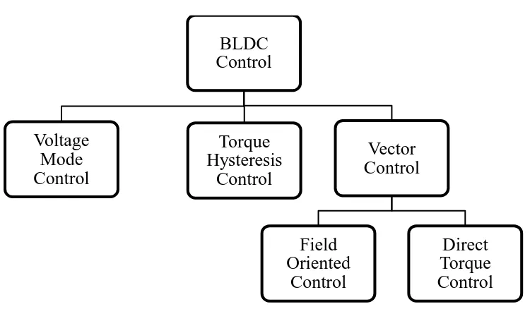
Oriented Control (FOC) and Direct Torque Control method. Figure 1.1 shows the BLDC
motor control.
THC is one of the technique to control the torque and phase current of the BLDC
machine. This method is used to replace the conventional voltage control that results in very
high current overshoot. The value of torque and current stay within certain limit in hysteresis
band by using THC, as it will provide current protection. However, the drawback of THC is
poor current or torque regulation performance. This disadvantage of THC encourages the
development of two-phase DTC in order to have better regulation performance [1]. However,
the use of DTC may give another problem namely higher switching frequency eventhough it
operates based on two-phase conduction mode. Later, this thesis will prove that high switching
frequency in DTC compared to that obtained in THC.
As for the FOC, it is use to decouple the control of flux and torque. The main
2
transformation that requires information on the instantenous positon of the appropriate flux
space vector [2].
Theory and principles of Direct Torque Control was introduced in the mid 1980's [2].
It is a newer concept and have been quickly accepted in industry in only ten years rather than
twenty years for vector control [2-3]. First implementation of DTC was originally developed
for induction machine drives. However, this project are focusing on DTC of BLDC. These two
fundamental of DTC of IM and DTC of BLDC are having slightly different and will be
explained further. DTC requires simple signal processing method. In its basic form, DTC give
simple control structure as it is sensitive to only variation of stator resistance [3,21]. Figure 1.2
and Figure 1.3 shows the control stucture between DTC and FOC. DTC recognizes that, it is
possible to control flux and torque directly. The idea of DTC development was initiated from
conventional vector control strategy. In vector control approach, the flux and torque able to be
controlled instantenously using the respective producing current components. Similarly to that
of DTC approach where the flux and torque can be controlled simultaneously based on the
respective flux and torque error status to select the suitable voltage vectors for satisfying the
demands.
Error exist in torque and flux can be used directly to drive the inverter without any
current control loops that necessary for co-ordinate transformation in conventional FOC [3] is
the basic idea of DTC. In order for the errors in flux and torque remain within the hysteresis
bands, the output from the flux and torque controller are used to determine which of the
possible inverter states should be applied to the machine terminal. In torque mode operation,
3
hysteresis controller. Thus, MATLAB/SIMULINK will be used as a simulation tools to
analyze the performance of THC and DTC.
In addition, an accurate mathematical model of a Brushless DC Motor (BLDC) is
important in DTC. It is fact that BLDC have become current trend for many applications.
Computer hard drives, electronic-component cooling fans, electric or hybrid car are those that
rely on BLDC motor [4-6]. BLDC known as synchronous motor because the rotor and stator
turn at the same frequency. Thus, it eliminating slip that is normally seen in induction
machine. Besides, BLDC is capable of providing large amount of torque over a vast speed
range and is consider to be high performance motor drives.
Figure 1.1 : BLDC Motor Control BLDC
Control
Voltage Mode Control
Torque Hysteresis
Control
Vector Control
Field Oriented
Control
4
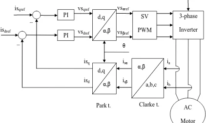
Figure 1.2: Basic Scheme of FOC of AC Motor
Figure 1.3: Basic Scheme of DTC of AC Motor
Voltage Source Inverter Switching Table Flux Control Torque Control Flux and Torque Estimator Induction Motor Tref _ + + _
Te Ψact
θψ
∆T
∆ψ Sa,b,c
AC Motor 3-phase Inverter SV PWM α,β d,q α,β d,q a,b,c α,β PI PI _ _ isqref isdref vsqref vsdref vsαref vsβref ia ib
isα
5
1.2 Significant of Research
Nowadays, the research on brushless DC motor (BLDC) drives has received enormous
attention due to its excellent dynamic response, high efficiency, wide speed and high torque
capability performances. It is known that the BLDC motor is the best option among other
types of motor to replace the conventional brushed DC motor as it can achieve comparable DC
motor performance however with less maintanence due to elimination of commutators and
brushes in its construction. Moreover, the construction of BLDC motor allows the speed to
operate for wide speed of range operations. However, the component used for the proposed
topologies that is DTC of BLDC is lesser than the conventional (FOC). Thus, the
implementation cost can be reduced.
In addition, it is well known that DTC has gained popularity because it offers excellent
torque dynamic control. In DTC, it operates in phase conduction mode; where only
two-phase produce switching at one time. As opposed to conventional THC method, the switching
resulted in three-phase. It is engaged that the switching in DTC produces lower switching
frequency and hence switching losses than that obtained in THC. However, the simulation
results indicate otherwise. Meaning that, DTC produce higher switching frequency than THC.
Thus, the significant of study is to prove that the switching frequency in THC is lower than
DTC for every speed operating ranges.
6
1.3 Problem Statement
In the last two decade, several variations of BLDC drives have been proposed which
includes the use of torque hysteresis controller (THC), and direct torque control (DTC).
However, these methods have an essential difference in their implementation. The major
problem in THC method is poor torque regulation performance. Current or torque ripple is not
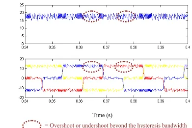
restricted within predefined hysteresis bandwidth. Simulation result in Figure 1.4 shows the
torque or current regulation performance in THC.
Figure 1.4 : Torque and Current Regulation Performance of THC
Besides, larger torque ripple in hysteresis controller both for DTC and THC need to be
minimized ideally by reducing the bandwidth. However, reduce hysteresis bandwidth produce
high frequencies since the regulation within bandwidth is more often. It shorten the time to
Tor
que
(
Nm)
C
ur
re
nt (A
)
= Overshoot or undershoot beyond the hysteresis bandwidth
7
travel (torque variation in bandwidth) from one band to another band. This phenomena lead to
production of frequency exceed beyond the limitation of switching device known as IGBT. It
affects the performance of the IGBT in terms of drop voltage, efficiency and the reliability of
the switching device itself. Note that, it is desirable to provide high power efficiency of the
BLDC drive system in order to prolong the energy battery source. The high switching
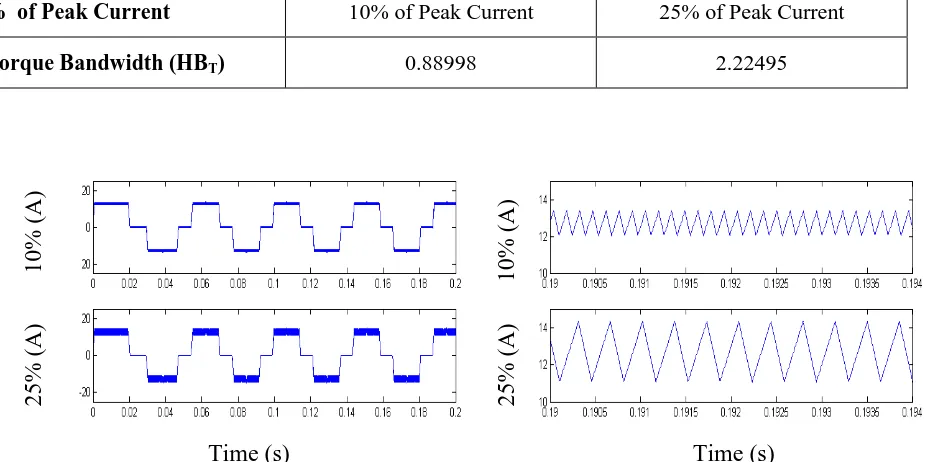
frequencies caused in DTC is highlighted by using simulation results in Figure 1.5. It can be
observed from right hand side of the figure (after zooming) that the switching frequency of
DTC is high when small bandwidth is applied. It is analyzed by referring only to current in
phase A. The torque hysteresis bandwidth (HBT) is calculated in terms of percentage of peak
current which is 12.714A and Table 1-1 below is the value of bandwidth for each percentage
of current.
Table 1-1: Percentage and Torque Bandwidth in DTC
% of Peak Current 10% of Peak Current 25% of Peak Current
Torque Bandwidth (HBT) 0.88998 2.22495
Figure 1.5 Switching Frequency Based on Hysteresis Bandwidth In DTC
8
1.4 Objective
The aims of this project are to:
i. model and simulate the Direct Torque Control (DTC) of Brushless DC Motor
(BLDC) by using Matlab or Simulink.
ii. analyze and compare the switching frequency and torque/current control
performances produced in Direct Torque Control (DTC) and Torque Hysteresis
Control(THC) of Brushless DC Motor (BLDC) drive.
1.5 Scope of Research
This project mainly focuses on:
i. Mathematical modeling of BLDC motor.
ii. Modeling and simulation of DTC for BLDC motor using Matlab or Simulink.
iii. Evaluate the performances of DTC and THC of BLDC motor in terms of switching
frequency and torque/current control.
1.6 Research Methodology
Upon completion of this research, several steps of process are made according to a
sequence. All the steps or procedures in conducting this research are briefly explained in