i
“I hereby declared that I have read through this report and found that it has comply the partial fulfillment for awarding the degree of Bachelor of Electrical Engineering
(Control, Instrumentation and Automation)”.
Signature : ………...
Supervisor’s Name : MR. SYED NAJIB BIN SYED SALIM
ii
REAL-TIME FUZZY LOGIC POSITION CONTROLLED DC MOTOR DRIVES
GWYNNIE CHEMBAT AKIN
This Report Is Submitted In Partial Fulfillment of Requirements for the Degree of Bachelor in Electrical Engineering (Control, Instrumentation and
Automation)
Fakulti Kejuruteraan Elektrik Universiti Teknikal Malaysia Melaka
iii
“I hereby declared that this report is a result of my own work except for the excerpts that have been cited clearly in the references.”
Signature : ………...
iv
ACKNOWLEDGEMENT
v
ABSTRACT
vi
ABSTRAK
vii
TABLE OF CONTENTS
CHAPTER ITEM PAGE
SUPERVISOR’S DECLARATION i
TITLE ii
DECLARATION iii
ACKNOWLEDGEMENT iv
ABSTRACT v
ABSTRAK vi
TABLE OF CONTENTS vii
LIST OF TABLES x
LIST OF FIGURES xi
LIST OF ABBREVIATION xv
LIST OF APPENDICES xvi
1 INTRODUCTION 1
1.1 Background 1
1.2 Concept of Project 2
1.3 Objective 3
1.4 Scope of Project 3
1.5 Problem Statement 1.6 Outline of Report
6 6
2 LITERATURE REVIEW 2.1 Previous Project
2.1.1 PID Position Control System 2.1.2 Fuzzy Logic Position Controller
viii
3
2.1.3 Comparison of the Experimental Results
2.1.4 Discussion 2.1.5 Conclusion 2.2 Control System Theory 2.2.1 Fuzzy Logic Controller 2.2.2 PID Controller
2.2.3 Conclusion 2.3 Microntroller
2.3.1 Comparison between Microcontrollers 2.3.2 Conclusion
2.4 Voltage Regulator 2.5 Serial Level Converter 2.6 Motor Driver
2.6.1 H-Bridge
2.6.2 Integrated Circuit 2.6.3 Conclusion 2.7 Electric Motor 2.7.1 DC Motor 2.7.2 Stepper Motor 2.7.3 Conclusion 2.8 Rotary Encoder
2.8.1 Absolute Rotary Encoder 2.8.2 Relative Rotary Encoder 2.8.3 Conclusion
METHODOLOGY 3.1 Overview
3.2 Modeling
3.2.1 Modeling of DC Motor
3.2.2 Step for Design Fuzzy Controller 3.3 Circuit Component
ix
4
5
3.3.1.1 Step Programming the Microcontroller
3.3.2 Serial Level Converter 3.3.3 H-Bridge
3.3.4 Position Encoder
3.4 Step for Design Circuit Using Proteus 3.5 Build Circuit with Strip board
3.6 List of Component
RESULT AND DISCUSSION 4.1 Modeling in Simulink 4.1.1 Matrix 3x3
4.1.1.1 Result 3x3 4.1.2 Matrix 5x5
4.1.2.1 Result 5x5 4.1.3 Discussion
4.1.4 Conclusion 4.2 Simulation in Proteus 4.2.1 Discussion
CONCLUSION AND RECOMMENDATION 5.1 Recommended
REFERENCES
APPENDIX
55
56 57 58 58 60 61
62 62 62 65 67 69 71 73 77 77
78 79
80
x TABLE 2.1 2.2 2.3 2.4 2.5 2.6 2.7 2.8 2.9 2.10 2.11 2.12 2.13 3.1
LIST OF TABLES
ITEM
Voltage-Speed Data
Fuzzy Rule Matrix for DC Motor Position Control
Fuzzy Rule Table Fuzzy Linguistic Terms
Proto-Type of Fuzzy Control Rules with Term Sets (Negative, Zero, Positive)
Proto-Type of Fuzzy Control Rules with Term Sets (NL, NM, NS, ZR, PS, PM, PL)
Summarizes the PID Terms and Effect on a Control System
Comparison Types of Method Tuning the PID Controller
Comparison between Microcontrollers Logic Truth Table
Comparison between Stepper and DC Motor Comparison Logic between Standard Binary and Gray Encoding
Comparison between Absolute and Relative Error List of Component
xi FIGURE 1.1 1.2 1.3 2.1 2.2 2.3 2.4 2.5 2.6 2.7 2.8 2.9 2.10 2.11 2.12 2.13 2.14 2.15 2.16
LIST OF FIGURES
ITEM
Concept of Project Block Diagram Figure 1.2: K-Chart Block Diagram
Real-Time Fuzzy Logic Position Controlled DC Motor Drives Block Diagram
Block Diagram of the PC-Based DC Motor Positioning System
PID Position Controller
Fuzzy Logic Position Controller Block Diagram Membership Functions
Simulation Result of Moving the Motor from 0˚ to 180˚
Measured Position Error and Control Output Voltage PID Controller
Measured Position Error and Control Output Voltage FLC Controller
Fuzzy Logic Control System Block Diagram Signals Flowing In and Out of a Fuzzy Controller Block Diagram
Example of a Membership Function
Three different Shapes of Membership Functions Observation of System Response for deriving PID Control System Block Diagram
PIC18F2431 Pin Diagram PIC18F4331 Pin Diagram PIC16F877A Pin Diagram
xii 2.17 2.18 2.19 2.20 2.21 2.22 2.23 2.24 2.25 2.26 2.27 2.28 2.29 2.30 2.31 2.32 3.1 3.2 3.3 3.4 3.5 3.6 3.7 3.8 3.9 3.10 3.11 3.12 3.13 3.14 3.15 PIC16F877A Voltage Regulator MAX232
MAX232 Pin Diagram H-Bridge Schematic Diagram Switching Control for Clockwise
Switching Control for Counter Clockwise Functional Block Diagram of LMD18200 Connection Diagram and Ordering Information LMD18200
The Common Motor Layout DC Motor
Operation of DC Motor Rotation of Stepper Motor
Comparison Design between Standard Binary and Gray Encoding
Incremental Encoder
Flow Chart of Methodology
Flow Chart of Real-Time Fuzzy Logic Position Controlled DC Motor Drive
Crystal Oscillator and Capacitor Circuit Diagram PIC Circuit
Voltage Regulator Connection Diagram Voltage Regulator Circuit
PIC Programmer
MAX232 Connection Diagram MAX232 Circuit
The H-Bridge Circuit Diagram H-Bridge Circuit
Feedback (Position) Circle Ruler
xiii 3.16 4.1 4.2 4.3 4.4 4.5 4.6 4.7 4.8 4.9 4.10 4.11 4.12 4.13 4.14 4.15 4.16 4.17 4.18 4.19 4.20 4.21 4.22 4.23 4.24 4.25 4.26 4.27 4.28
Real-Time FLC Position Controlled DC Motor Drive
Membership Function for Input Thetaerror Membership Function for Input Speed Membership function for output voltage Rules of FLC
Rules view of rules Position Waveform Speed Waveform Current Waveform Torque Waveform
Membership Function for Input Thetaerror Membership Function for Input Speed Membership Function for Output Voltage Rules of FLC
Rules view of rules Position Waveform Speed Waveform Current Waveform Torque Waveform
Error at Speed Waveform for Matrix 3x3 Rule Error at Speed Matrix 5x5 Rule
No Error at Position Waveform for 3x3 Rule Error at Position Waveform Matrix 5x5 Rule Circuit for Communication Test
xiv
COA COG CMOS DMOS DC FLC GUI IEEE
I/O MOSFET
PIC PID PSM PWM
LIST OF ABBREVIATION
Center-of-Area Center-of-Gravity
Double-Diffused Metal Oxide Semiconductor Complementary Metal-Oxide Semiconductor
Direct Current
Fuzzy Logic Controller Graphical User Interface
International Electrical Electronic Engineering Input/Output
Metal-Oxide Semiconductor Field-Effect Transistor
Programmable Integrated Circuit Proportional, Integral, Derivative Projek Sarjana Muda
xv
INDEX
A B C D E F G H I J K
LIST OF APPENDICES
ITEM
Hardware Layout Program
Ghant Chart Circuit Diagram Modeling
IRF530N Datasheet IRF9530N Datasheet Motor Datasheet Encoder Datasheet PIC16F877A Datasheet Voltage Regulator
PAGE
1
CHAPTER 1
INTRODUCTION
The “Real-Time Fuzzy Logic Position Controlled DC Motor Drives” project is needed interface software and hardware. This project is build to control the performance of dc motor for positioning purpose and controlled by fuzzy logic controller. Beside that, this project is build to comprehend the basic concepts of fuzzy logic. In this chapter will discuss about general background, concept of project, objective, scope, problem statement and report outline.
1.1 Background
Motion control deals with the use of high performance electric motor and is a very important part industrial control systems. Motion control includes application for position control in practically all branches of industry. An important advance in this field has been made during the last years by the introduction of microprocessor control systems. These systems are becoming a standard in motion control because of fast advances in microelectronics technology and well-known benefits such as greater accuracy, parameter sensitivity and higher interconnection capacity.
2 solutions, efforts are being made to continuously decrease the cost of these systems, especially considering their power electronics and control parts.
1.2 Concept of Project
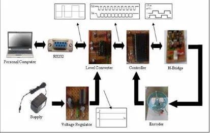
The concept of this project is shown in figure 1.1. Firstly, the controller works by receiving a user position command then drive a dc motor to desire position by using Serial Watcher. After receiving direction and position command from computer, the controller will compare the actual and desire position to determine the required pulse width modulation to drive a dc motor. The controller observes the actual position of the position output shaft from the position encoder. The position encoder attached at the output shaft motor.
3 1.3 Objective
The objectives of the project are:
To perform a modeling of dc motor.
To make comparison between difference matrix. To realize the operation of fuzzy logic for dc motor.
To investigate the result of output response according to a controller, load and input.
1.4 Scope of Project
The K-Chart of the project is shown in figure 1.2. Firstly, with perform modeling dc motor to get a parameter of dc motor by calculation. Then, design fuzzy logic by using Matlab(simulink). After design a fuzzy logic block and 3x3 and 5x5 rules, there will be make a comparison between it with analyze a waveform. Then, design a circuit by using Proteus (ISIS). After that, simulate the circuit with program put inside the microcontroller and make an analysis on it. Then, implement the circuit on the board. Finally, interface software with hardware then observe the result and make an analysis.
For this project, the close loop system is needed. The close loop system is used because it has a feedback function for monitoring the output position. The project circuit parts are consist PIC controller, driver, dc motor and position encoder as a feedback. The block diagram of this project is shown in figure 1.3. This project is design and implements the hardware and the Serial Watcher as the software.
5
Figure 1.2: K-Chart Block Diagram
6 1.5 Problem Statement
Most PID controller has been apply to the dc motor control position in industry but still have a weakness that need to improve it by using fuzzy logic controller.
The weaknesses of PID controller in application are the coefficients for the PID controller are tuned in Kp, Ki and Kd are still give an effect to the minimum settling time compare with the fuzzy logic controller which is the minimum settling time can be achieved by tuning the control rules, membership functions and universe of discourse of the output variable [1].
Beside that, by tuning and obtaining stable controller through trial-and-error method is still the basic method in improving the expert knowledge toward developing a tuned and stable fuzzy controller. But, it is an attempt to acquire proof of principle experience in the fuzzy logic control and not necessarily a breakthrough research in solving the proposed problem.
1.6 Outline of Report
7
CHAPTER 2
LITERATURE REVIEW
This chapter will discuss about a review of control system that are usually implemented in positioning system regarding on the previous researcher with including an example of project. Besides that, some theory on several parts of the project such as microcontroller, voltage regulator, level converter, motor driver, electric motor and rotary encoder are also mentioned.
2.1 Previous Project
This part will be mention about discussion and result from previous project. At last, there has a selection either choose fuzzy logic controller or PID controller are better. The title project is Comparison on Fuzzy Logic and PID Controls for a DC Motor Position Controller. This project was done by Paul I-Hai Lin, Santai Hwang and John Chou.
The specification of the PC-Based Position Servo which they are considering a PC-based DC motor position control (single input and single output) that will use either a PID controller or a fuzzy logic controller of the PD type. In this system, the motor angular position is to be controlled.
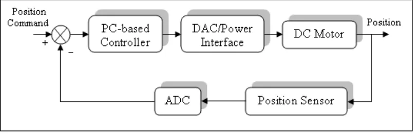
8 potentiometer for position feedback, a two stage preamplifier and a power amplifier. The block diagram of the system hardware is shown in figure 2.1. In addition, both fuzzy and PID control algorithms are implemented in C programming language and controllers are tuned with trial and error approach. The functions performed by both controllers are accepts user commands and reports status, reads the position feedback and calculates error, implements the transfer function and compensatory function then output the motor command.
The objectives for comparison are the maximum position error of 0.5˚, no overshoot and a minimum settling time.
Figure 2.1: Block Diagram of the PC-Based DC Motor Positioning System
The dc motor used in the PC-based position servo is a permanent magnet dc motor with the following parameters;
Ra = 1.5 ohms, armature resistance La = 2.3 mH, armature inductance Kt = 0.040832 Nm/Amp, torque constant Ke = 0.04098726 volt/rad * sec-1
J = 4.942 x 10
, back emf constant -5
kg-m2, rotor inertia
9
Two poles are given by;
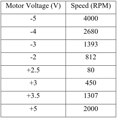
The motor was tested under no load condition to obtain some voltage speed data. The dead zone of the dc motor is around ±1.3V. The data is shown below;
Table 2.1: Voltage-Speed Data
An 8-bit digital to analog converter (D/A) and power amplifier provide the proper voltage levels for the dc motor. Signal amplifier stage uses two operational amplifiers to give a non-inverting voltage gain of 3.
The analog position sensor is a potentiometer with a single-turn and no rotation stops. The sensor feeds absolute position data to an 8-bit ADC (±5V, 20µs
Motor Voltage (V) Speed (RPM)
-5 4000
-4 2680
-3 1393
-2 812
+2.5 80
+3 450
+3.5 1307
+5 2000
( ) ( )
( )
t
a
e t a
a a
K
JL s
M s
V s K K R
s s s
JR L θ = = + +
22.7 / sec
e t
a K K
rad
R J =
652.2 / sec
a
a R
rad