DOI: 10.12928/TELKOMNIKA.v13i1.131 32
Implementation of Maximum Power Point Tracking on
Photovoltaic Using Fuzzy Logic Algorithm
Arton Johan Lubis1, Erwin Susanto2, Unang Sunarya3 1,2
Faculty of Electrical Engineering, Telkom University, Bandung, Indonesia 3 Faculty of Applied Science, Telkom University, Bandung, Indonesia
Jl.Telekomunikasi No 1.,Dayeuhkolot Bandung,40257 e-mail: [email protected], [email protected],
Abstract
Most energy sources that are commonly used in the world today are from fossils. This kind of energy is unrenewable and limited. Use of solar panels (Photovoltaic, PV) to generate electricity is growing fast and it can be used as an alternative energy instead of fossils. The problem faced by use of solar panels is that the generated power is not optimum for a particular load. It is always changing and influenced by the level of light (irradiance) and temperature. Therefore we need a way to maximize the power output of solar panels. Maximum Power Point Tracking (MPPT) is a method for finding its maximum power point. In this research, the MPPT is designed to locate the point of generated maximum power on solar panels. MPPT controller designed in this research is using fuzzy logic. The voltage and current from the solar panels are fed to the fuzzy logic controller. The output of fuzzy logic in the form of a pulse width modulation (PWM) signal regulates the process of switching boost converter. Experimental results show that output power from PV increase 15.9% and the efficiency of designed boost converter ranges in approximatelly 90.97%.
Keywords: PV, MPPT, fuzzy logic, PWM, boost converter
1. Introduction
Because of the increasing of population growth, demand for electricity also increases rapidly. In fact, most power sources obtained today are from fossil fuels that are not renewable and limited. Then, we need renewable energy sources to overcome the crisis in future. Photovoltaic is one of the renewable energy resources in recent years. However, PV modules still have low efficiency due to the atmospheric conditions until right now although the earth receives huge energy from the sun. Therefore, a system that can control and gain maximum power point tracking for the solar array is urgently needed [1].
The maximum power operating point changes with irradiation level and temperature. The characteristic curve specifies a unique operating point at which maximum possible delivered power. At the Maximum Power Point (MPP), the PV system operates at its highest efficiency. The MPPT working principle is based on the maximum power transfer theory. The power delivered from the source to the load is maximized when the input resistance seen by the source matches the source resistance. For the fixed load, the equivalent resistance seen by the panel can be adjusted by changing power converter duty cycle [2].
Many methods have been developed to determine the MPP such as the incremental conductance [1], a state space approach [2], and the perturbation and observation [3]. In the simplest method, i.e. [3], the system needs to be perturbed to sense the maximum point and it works well if the weather is constant or slowly changed. Otherwise, system cannot obtain its maximum point. Although incremental conductance method has high accuracy but it leaves difficult computation so that the response becomes slow and its implementation cost is relatively high because it uses digital signal processing (DSP) board [2]. In [2], mathematics model must be provided to track the maximum power point. However, the photovoltaic power generation system model is very complex since it contains non linear parameters.
The main parts of the built system include photovoltaic array, boost converter and fuzzy logic based MPPT controller.
2.1. Photovoltaic model
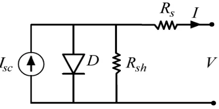
A solar cell is a p-n jucton semiconductor device. It recieves energy from the sun and convert it into electrical energy. The simple equivalent circuit of PV has been show in figure 1 which consists of a current source model of the luminous flux, the losses modeled by two resistor, shunt resistor Rsh, a series resistor Rs, and diode [8]-[11].
Figure 1. Equivalent circuit of PV
According to the figure 1, the I-V characteristic equation of a PV cell is given as:
(1)
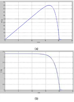
To illustrate the I-V and P-V characteristics [8], we simulate the PV module using Matlab-Simulink. Figure 2 shows the (I-V) and (P-V) characteristics with solar irradiance level and ambient air temperature in 1000W/m2 and 25oC, respectively. The photo-generated electric current depends on variable irradiance and ambient temperature.
2.2. Boost Converter
Boost converter is used to generate output voltage higher than input voltage. Figure 3 presents boost converter circuit which consists of inductor, diode, MOSFET, capacitor, and load [13]. Boost converter works in two states. During the switch S is open, electric current on the inductor increased linearly, and the diode D is turned off at the time. When the switch S is closed, the energy stored in the inductor is released through the diode to the output RC circuit.
The main equation associatedto duty cycle and input-output voltage of boost converter is given as follows:
(a)
(b)
Figure 2. (a) P-V curve and (b) I-V curve
Figure 3. Boost conveter
2.3. Fuzzy logic based MPPT controller
Figure 4 shows the overall system architecture. The proposed MPPT controller has been built upon the simplicity of fuzzy logic. This method is introduced for tracking the MPPT in PV system.The designed systems is robust and relatively simple as well as do not require the knowledge of the exact model [6].
Figure 4. MPPT system configurations
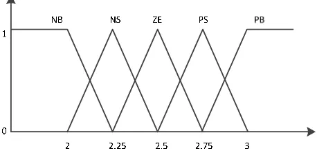
In this paper the FLC inputs are voltage input (Vin) and current input (Cin). The fuzzy output is duty cycle for switching dc boost converter. Figure 5 and Figure 6 present membership function of the voltage input (Vin), and current input (Cin).
Figure 5. Membership function of voltage input
Figure 6. Membership function of current input
3. Results and discussions
Implementation of FLC based MPPT yields some measurement data as follows
3.1. Solar panel characteristic
In this section the form of characteristic curves indicate voltage - current and voltage - power measurement results using PV solar panels Sunlik SL050-12M.
Figure 7. Voltage versus current curve
Figure 8. Voltage versus power curve
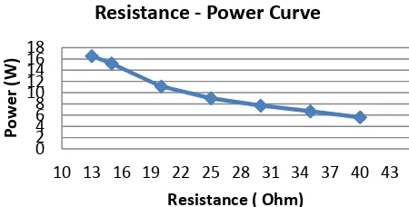
Experimental test is done by connecting the solar panel to the load, then the voltage and current measurement issued by the solar panels are measured with a varying load. The maximum power point 42.3 Watt is obtained for the voltage 16.87 Volt and the current 2.51 Ampere. Relation between the load resistance and the power can be figured in Figure 9.
Figure 9. Load versus power curve 0
1 2 3
1 2 3 4 5 6 7 8 9 101112131415161718192021
Current (
1 2 3 4 5 6 7 8 9 101112131415161718192021
Figure 10. Reading of electric currents by a multimeter and the current sensor
The calculation of output current error is:
ƞ %
ƞ . %
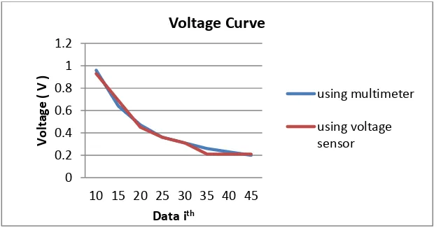
3.3. Testing and analysis of voltage sensor
The purpose of measurement is to look at the performance of the voltage sensorby reading the voltagesdiferenceof power supply voltage and voltage sensor output with fixed load 30 ohm. Voltage is one of the inputs to the fuzzy supporting fuzzy output accuration.
The accuracy of the experimental data is done as
ƞ %
ƞ . %
The test result on the fixed irradiance shows that the measurement error of voltage sensor and a multimeteris 0.97 % and it can be considered quite well.
3.4. Testing and analysisof boost converter series
The test is taken to measure the power efficiency regarding to the duty cycle variations.
Tabel1. Voltage test results on boost converter circuit
PWM Duty-cycle (%) Vin (V) (A) Iin Vout (V) Iout (A)
Power efficiency
(%)
11 4.3 5 0.24 4.92 0.24 93.08 22 8.7 5 0.26 4.98 0.25 94.32 34 13.4 5 0.29 5.23 0.26 92.3 38 15 5 0.31 5.33 0.26 87.03 55 21.6 5 0.36 5.73 0.29 91.02 78 31 5 0.46 6.46 0.33 92.10 90 35 5 0.53 6.87 0.35 90.23 102 40 5 0.61 7.73 0.37 94.22 115 45 5 0.71 7.84 0.4 88.38 128 50 5 0.86 8.48 0.44 87.29
Average 90.97
The average of power efficiency is obtained by using the formula :
ƞ P P P x %
ƞ %
ƞ = 90.97 %
3.5 Testing and analysisof MPPT implementation
Figure 12. MPPT vs non-MPPT power performance
It can be seen that the output power generated by the solar panels that are connected to the MPPT system produces more power than the solar panels that do not use MPPT. The performance of the output power with MPPT is obtained as:
ƞ x %
ƞ . . . %
ƞ . %
The calculation shows that the efficiency of the power output of solar panels using MPPT system is increased 15.9 % compared to non-MPPT system with a constant load of 8.6ohm
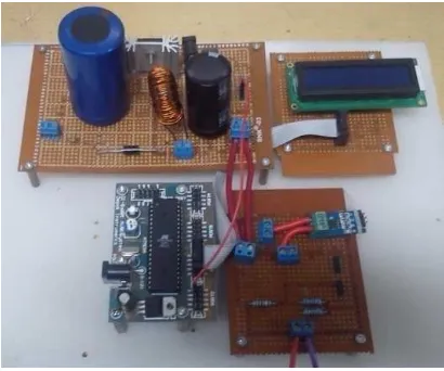
Figure 13. MPPT hardware implemented in the system 25
26 27
1 2 3 4 5 6 7 8 9 10 11 12 13 14 15 16 17 18 19 20
Power
Number of Experiment
4. Conclusion
The implementation of MPPT using fuzzy logic controller is presented. Measurement and data analysis show that the proposed method can be applied well. The power boost converter input and output are not same; it shows the presence of losses due to the converter switching process. The efficiency boost converter designed is about 90.97%. Test results with a power output of MPPT and non-MPPT with a load of 8.6 ohm show that the MPPT power efficiency increases 15.9%.
References:
[1] K Hussein, I Muta, T Hoshino, M Osakada. Maximum photovoltaic power tracking: an algorithm for rapidly changing atmospheric conditions. Proc. Inst Elect. Eng. 1995; 142(1): 59-64.
[2] EV Solodovnik, S Liu, RA Dougal. Power controller design for maximum power tracking in solar installations. IEEE Trans. Power Elect. 2004; 19(5): 1295-1304.
[3] O Wasynczuck. Dynamic behavior of a class of photovoltaic power systems. IEEE Trans. Power Apparat. Syst. 1983; PAS-102(9): 3031-3037.
[4] Y Zhao, X Zhao, Y Zhang. MPPT for photovoltaic system using multiobjective improved particle
swarm optimization algorithm. TELKOMNIKA Indonesian Journal of Electrical Engineering. 2014;
12(1): 261-268.
[5] M Yaichi, MK Fellah, A Mammeri. A Neural Network Based MPPT Technique Controller for Photovoltaic Pumping System. International Journal of Power Electronics and Drive Systems (IJPEDS). 2014; 4(2): 241-255.
[6] M Algazara, H Al-Monierb, HA El-Halima, ME Kotb Salem. Maximum power point tracking using fuzzy logic control. International Journal of Electrical Power & Energy Systems. 2012; 39(1): 21-28. [7] H Bounechba, A Bouzid, K Nabti, H Benalla. Comparison of perturb & observe and fuzzy logic in
maximum power point tracker for PV systems. Energy Procedia. 2014; 50: 677-684.
[8] J Kida, K Tokuda, Y Ishihara, T Todaka. Analysis of DC-DC converter for the maximum power point control of photovoltaic. INTELEC'91, IEEE Proceedings. 1991: 291-295.
[9] S Yan, J Yuan, L Xu. Fuzzy logic control of MPPT for photovoltaic power system. Proc. 9thInternational Conference on Fuzzy Systems and Knowledge Discovery. 2012: 448-45.
[10] N Pandiarajan, R Muthu. Mathematical modeling of photovoltaic module with Simulink. Proc. Electrical Energy Systems (ICEES). 2011: 258-263.
[11] MH Rashid. Power Electronics: Circuits, Devices and Applications. Prentice Hall. Fernuniversität-Gesamthochschule Hagen in Germany. 1988.
[12] T Esram, PL Chapman. Comparison of photovoltaic array maximum power point tracking technique.
IEEE Trans. Energy Conversion. 2007; 22(2): 439-449.