DEVELOPMENT OF FUZZY LOGIC SPEED CONTROLLER FOR DC MOTOR APPLICATIONS
USING RABBIT MICROPROCESSOR
LIM SENG KEAT
DEVELOPMENT OF FUZZY LOGIC SPEED CONTROLLER FOR DC MOTOR APPLICATIONS BY USING RABBIT MICROPROCESSOR
LIM SENG KEAT
This report is submitted in partial fulfillment of requirements for the Degree of Bachelor In Electrical Engineering (Power Electronics and Drives)
Faculty of Electrical Engineering Universiti Teknikal Malaysia Melaka
ii “I hereby declared that I have read through this report and found that it has comply the partial fulfillment for awarding the degree of Bachelor of LEectrical Engineering (Power Electronics and Drives).”
Signature: _____________________________________ Name :Associate Professor Dr. Zulkifilie bin Ibrahim
iii “I hereby declared that this report is a result of my own work except for the excerpts that have been cited clearly in the references.”
Signature:____________________________________ Name : LIM SENG KEAT
iv ACKNOWLEDGEMENT
v ABSTRACT
The project is titled as “Development of Fuzzy Logic Speed Controller for DC Motor Applications by Using Rabbit Microprocessor.” In this project, the embedded controller developed is based on Rabbit microprocessor and its core module model RCM 3100. The control method implemented in this is fuzzy logic control method. A fuzzy logic algorithm needs to be developed and be compiled in Rabbit microprocessor in order to provide precise control signal for DC motor variable speed drive. Instead of using assembly language to compile the fuzzy algorithm, this controller will use Dynamic C programming language to develop the algorithm.
.
The goal of the project is to design and develop a laboratory scale functioning prototype in order to demonstrate the interfacing between the fuzzy logic control algorithm in Rabbit microprocessor and the DC motor speed drive. The Rabbit microprocessor based fuzzy controller is able to generate Pulse Width Modulation (PWM) signal. The PWM signal generated is an input signal for H-bridge DC power converter in order to control the speed of DC motor.
vi ABSTRAK
Projek ini bertajuk “Pembangunan pengawal kelajuan digital fuzzy logic untuk aplikasi motor DC dengan menggunakan mikropemproses Rabbit,” dalam projek ini, satu pengawal padat yang dibangunkan adalah berteraskan mikropemproses Rabbit dan modul tersnya RCM 3100. Cara pengawal atur yang digunakan dalam projek ini adalah cara kawalaturan fuzzy logic. Satu algoritma fuzzy logic perlu dibangunkan dan dikompil ke dalam mikropemproses Rabbit agar dapat memberikan isyarat kawalan yang tepat kepada pemacu kelajuan motor DC. Daripada menggunkan bahasa himpunan, pengawal yang direkacipta ini menggunakan bahasa pengaturcaraan Dynamic C yang dikhaskan untuk mikropempemproses Rabbit.
Matlamat projek in adalah untuk merekacipta dan membangunkan satu prototaip yang berfungi dalam skala makmal. Prototaip ini diharapkan dapat mendemonstrasikan pengantaraan yang baik antara algoritma fuzzy logic yang dibangunkan dlam mikropemproses Rabbit, dengan pemacu kelajuan motor DC. Pengawal fuzzy asas mikropemproses Rabbit mampu menjanakan isyarat PWM. Isyarat PWM yang terjana akan dijadikan isyarat masukan untuk pemacu dan seterusnya pemacu kelajuan dapat mengawal kelajuan motor DC.
viii LIST OF CONTENTS
CHAPTER PAGE
LIST OF CONTENTS vii
LIST OF TABLES xi
LIST OF FIGURES xii
LIST OF ABBREVIATIONS xvii
LIST OF APPENDIX xviii
1 INTRODUCTION 1
1.1 Objectives 2
1.2 Scope of project 2
1.3 Problem statement 3
2 LITERATURE REVIEW 6
2.1 Embedded Systems and Embedded Controllers 6 2.2 Rational of Motor Speed Control
2.2.1 Shunt field control
2.2.2 Armature voltage control 2.2.3 PWM speed control
10 11 11 12 2.3 Fuzzy logic
2.3.1 Introduction
2.3.2 Fuzzy logic control algorithm 2.3.3 Advantage of fuzzy logic control
2.3.3.1 Fuzzy logic as a simpler and faster design methodology
ix 2.3.3.3 Fuzzy logic is more robust and faster 20
3 PROJECT METHODOLOGY 21
3.1 Introduction 21
3.2 Hardware Part Process
3.2.1 Rabbit microprocessor Rabbit 3000
3.2.1.1 Features and specifications of Rabbit 3000
3.2.1.2 The CPU of Rabbit 3000
3.2.1.3 Parallel I/O 3.2.1.4 Parallel Port A 3.2.1.5 Parallel Port F 3.2.1.6 PWM channels
3.2.2 Rabbit Core Module, RCM 3100
3.2.3 Operation of H-bridge DC Power Converter 3.2.4 DC motor
3.2.5 Feedback Circuit
3.2.6 Analogue-to-digital converter, ADC0802
24 24 25 26 28 29 30 32 34 37 38 40 41 3.3 Dynamic C (Integrated Development System)
3.3.1 Code compilation and running
3.3.1.1 Code building in conventional development environment 3.3.1.2 Code building with Dynamic C 3.3.2 Initialization of Parallel I/O Ports Using Dynamic C 46 49 49 51 52
3.4 Measurement, Testing and Support Equipment 3.4.1 Digital Oscilloscope
3.4.2 Digital Multimeter
3.4.3 Variable DC Voltage Power Supply
56 56 58 59
4 DESIGN AND DEVELOPMENT OF HARDWARE PROTOTYPE BOARD
61
x 4.2 Hardware connection of RCM 3100 62
4.3 Development of H-bridge DC Motor Driver 64 4.4 Development of Feedback System 68 4.5 PWM Generation by Microprocessor Rabbit 3000 70
4.6 Interfacing among H-bridge Driver, DC Motor and RCM 3100
72
4.7 Interfacing between Analogue-to-Digital Converter ADC0802 and Rabbit 3000
73
5 DEVELOPMENT OF SOFTWARE ALGORTIHM
FOR FUZZY LOGIC CONTROLLER
75
5.1 Constraint in Conventional Controller Design 75 5.2 Fuzzy Logic Controller Designing Procedure 76 5.3 Fuzzification and Membership Function 78
5.4 Formation of the Rule Base 82
5.5 Defuzzification 85
5.6 Fuzzy Logic Algorithm in Dynamic C 87
6 EXPERIMENTAL RESULT AND PERFORMANCE ANALYSIS
90
6.1 Experimental Setup and Testing Procedure 6.1.1 The hardware interfacing connection setup.
90 91 6.2 Step Response with Initial Fuzzy Set Partitions 97 6.3 Response to Step Reduction of Speed Command, and Load Disturbance
99
6.4 FLC Performance with Minimum Overlapped Base Width of Fuzzy Set
101
6.5 FLC Performance with Maximum Point of Fuzzy Set Closed to Origin
105
6.6 FLC Performance with Maximum Point of Fuzzy Set Far Away from Origin
107
6.7 FLC Performance with Reduction of Universe of Discourse for Fuzzy Output Variable
xi 6.8 Performance Analysis of the Fuzzy Logic Speed
Controller
114
7 CONCLUSIONS AND RECOMMENDATIONS 116
7.1 Conclusion 116
7.2 Recommendations for future development 120
REFERENCE 122
xii LIST OF TABLES
PAGE Table 3.1 Parallel Port A Registers of RCM 3100 29 Table 3.2 Parallel Port A Data register Bit Functions of RCM 3100 29 Table 3.3 Parallel Port F Registers of RCM 3100 30 Table 3.4 Parallel Port F Register Functions of RCM 3100 31
Table 4.1 Components required for H-bridge driver construction 65
Table 5.1 Universe of discourse for input and output variables of the fuzzy logic controller
77
Table 6.1 Pin configuration and connection of RCM3100 94 Table 6.2 The pin configuration and connection of L6205 for hardware
interfacing.
95
Table 6.3 The pins connection of ADC0802 for hardware interfacing. 96 Table 6.4 Experimental result for FLC with initial setting 99 Table 6.5 Experimental result with minimum overlapped of input
variable fuzzy set
104
Table 6.6 Experimental result with maximum point of input variable fuzzy set is far away from origin
109
Table 6.7 Experimental results with reduction of universe of discourse for fuzzy output variable
xiii LIST OF FIGURES
PAGE
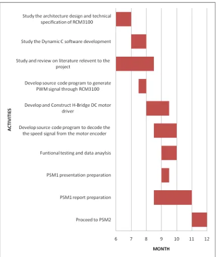
Figure 1.1 Gantt chart for PSM 1. 4
Figure 1.2 Gantt chart for PSM 2. 5
Figure 2.1 IBM PC motherboard 7
Figure 2.2 PC 104 stack module. 8
Figure 2.3 JK Microsystems Mini ITX based embedded PC. 8 Figure 2.4 PWM waveforms with different duty cycle. 12 Figure 2.5 Designing steps for conventional controller. 17 Figure 2.6 Designing steps for fuzzy logic controller. 17 Figure 2.7 Lookup table versus rules and membership functions. 20
Figure 3.1 Block diagram of fuzzy logic speed controller using Rabbit 3000 microprocessor.
23
Figure 3.2 Block diagram of a fuzzy logic controller. 23
Figure 3.3 Rabbit 3000 in LQFP package. 24
Figure 3.4 Rabbit 3000 block diagram. 27
Figure 3.5 Timer synchronous output allow for precise timing of output pulses.
28
Figure 3.6 Block diagram of the PWM modulator in Rabbit 3000. 33 Figure 3.7 Open-drain mode and spread mode of PWM modulator in
Rabbit 3000.
33
xiv Figure 3.9 Subsystems of the Rabbit Core Module RCM 3100. 35
Figure 3.10 Rabbit Core Module, RCM 3100. 35
Figure 3.11 Nomenclature of an H-bridge using MOSFET. 37
Figure 3.12 DC motor. 38
Figure 3.13 Equivalence electrical circuit of a DC motor. 39 Figure 3.14 Relation of motor speed in voltage reference to DC voltage
supply.
39
Figure 3.15 Feedback system. 40
Figure 3.16 Circuit diagram of feedback system. 40 Figure 3.17 Block diagram of successive approximation
analogue-to-digital converter.
42
Figure 3.18 Conversion process from analogue signal into digital equivalence in ADC0802.
43
Figure 3.19 Pin layout of ADC0802. 44
Figure 3.20 Flow of code building using conventional development environment.
50
Figure 3.21 Flow of code building using Dynamic C. 51 Figure 3.22 Block diagram of parallel port initialization. 53
Figure 3.23 Port initialization. 55
Figure 3.24 Digital oscilloscope. 56
Figure 3.25 Oscilloscope probe. 57
Figure 3.26 Digital multimeter. 58
Figure 3.27 Variable DC voltage power supply. 59
Figure 4.1 Attach the RCM3100 module to prototyping board. 62 Figure 4.2 Connect serial programming cable to serial port on RCM
3100.
63
Figure 4.3 Block diagram of DMOS dual full bridge driver (L6205). 64 Figure 4.4 Circuit connection diagram for a parallel bridge operation of
L6205.
66
Figure 4.5 H-bridge driver (L6205) implemented with a logic inverter 74LS04.
67
xv Figure 4.7 The constructed speed signal feedback system. 69 Figure 4.8 Connection diagram of the speed signal feedback system. 69 Figure 4.9 Flow to generate PWM signal using Rabbit 3000. 70 Figure 4.10 PWM signal generated using microprocessor Rabbit 3000.
(a) PWM signal with 1020 counts, duty cycle = 99.6%. (b) PWM signal with 200 counts, duty cycle = 19.53%. (c) PWM signal with 500 counts, duty cycle = 48.83%.
71
Figure 4.11 Testing flow for interfacing among H-bridge driver, DC motor and RCM 3100.
72
Figure 4.12 Circuit connection for interfacing between ADC0802 and Rabbit 3000.
74
Figure 4.13 Testing flow for interfacing between ADC 0802 and Rabbit 3000.
74
Figure 5.1 Linguistic division on a typical speed error profile. 78 Figure 5.2 Partition of input variable fuzzy sets using triangular
fuzzifier.
79
Figure 5.3 Definition of membership degree using triangular fuzzifier. 79 Figure 5.4 Block of source code that performs membership degree
calculation.
80
Figure 5.5 Source code in Dynamic C to define a triangular fuzzifier. 81 Figure 5.6 The singleton representation for output variables. 84 Figure 5.7 Block of source code that defined the rule base in singleton
representation.
84
Figure 5.8 Block of source code that performs singleton defuzzification. 86 Figure 5.9 The control flow of fuzzy logic algorithm that developed in
Dynamic C.
88
Figure 5.10 State diagram for fuzzy logic controller algorithm developed in Rabbit 3000.
xvi Figure 6.1 Block diagram of the overall fuzzy logic controlled DC
motor drive experimental setup.
92
Figure 6.2 Experimental setup. 93
Figure 6.3 Input and output variable fuzzy set partition for initial testing condition.
97
Figure 6.4 Step response with varied speed reference. (a) Speed reference = 1.0 V.
(b) Speed reference = 1.5 V. (c) Speed reference = 2.0 V. (d) Speed reference = 2.5 V. (e) Speed reference = 3.0 V.
98
Figure 6.5 Response of FLC to reduction of speed command and load disturbances.
100
Figure 6.6 Original partition for input variable fuzzy set. 101 Figure 6.7 Input variable fuzzy set partition with minimum overlapped
region.
102
Figure 6.8 Step response with input variable fuzzy set minimum overlapped.
(a) Speed reference = 0.5 V. (b) Speed reference = 1.0 V. (c) Speed reference = 1.5 V. (d) Speed reference = 2.0 V. (e) Speed reference = 2.5 V. (f) Speed reference = 3.0 V.
103
Figure 6.9 Maximum point of input variable fuzzy set tuned to close to the origin.
xvii Figure 6.10 Step response results in oscillation.
(a) Speed reference = 0.5 V. (b) Speed reference = 1.0 V. (c) Speed reference = 1.5 V. (d) Speed reference = 2.0 V.
106
Figure 6.11 Maximum point of input variable fuzzy sets tuned to be far away from the origin.
107
Figure 6.12 Step response with maximum input variable fuzzy set is far away from origin.
(a) Speed reference = 0.5 V. (b) Speed reference = 1.0 V. (c) Speed reference = 1.5 V. (d) Speed reference = 2.0 V. (e) Speed reference = 2.5 V.
108
Figure 6.13 Reduction of universe of discourse of the fuzzy output variable.
110
Figure 6.14 Step response with reduction of universe of discourse of output variable.
(a) Speed reference = 0.5 V. (b) Speed reference = 1.0 V. (c) Speed reference = 1.5 V. (d) Speed reference = 2.0 V. (e) Speed reference = 2.5 V. (f) Speed reference = 3.0 V.
112
xviii LIST OF ABBREVIAITIONDS
AC Alternating current
ADC Analogue-to-digital converter CPI Common Programming Interface DAC Digital-to-analogue converter DC Direct current
DSP Digital Signal Processor EMF Electromotive Force
EPROM Electrical Programmable Read-Only Memory
FL Fuzzy logic
FLC Fuzzy logic controller
IDE Integrated development environment ISA Industry standard architecture
LQFP Low Quad Flat Profile LSB Least significant bit
MOSFET Metal oxide silicon field effect transistor OEM Original equipment manufacturer
PC Personal computer
PCI Peripheral Component Interconnect PICMG PCI Industrial Manufacturer Group PWM Pulse width modulation
xix LIST OF APPENDIX
APPENDIX A PWM Generation
APPENDIX B Interfacing between H-bridge, DC motor and RCM 3100
APPENDIX C ADC0802 interfacing with Rabbit 3000
1
CHAPTER 1
INTRODUCTION
This project is titled as “Development of a fuzzy logic speed controller for DC motor applications using Rabbit microprocessor”. The purpose of this project is to provide a modular of fuzzy logic control algorithm in the aspect of DC motor speed controlling by using Rabbit Core Module 3100 prototyping board. The project development consisted of two major parts; hardware implementation and software development.
2
In the software part, the fuzzy logic control algorithm will be developed and implemented by using Dynamic C, a high level programming language developed by Rabbit Semiconductors especially for its microprocessor. In the means of high level programming language, the assembly language will not directly being applied in the development of fuzzy logic algorithm. The fuzzy logic algorithm programmed in C structure will be compiled into the memory system of Rabbit Microprocessor. As the result, the fuzzy controller developed is able to provide precise PWM signal in order to drive the DC driver. Lastly, the Rabbit microprocessor will be interfaced to the H-bridge DC power converter and DC motor to run in real time and debug.
1.1 Objectives
• To design and develop a digital fuzzy logic speed controller for DC motor applications using Rabbit microprocessor.
• To design and develop functional laboratory scale prototype fuzzy logic speed controller (FLC).
1.2 Scope of project
• To develop a DC motor speed controller by implementing fuzzy logic control method using Rabbit microprocessor.
3
1.3 Problem statement
In present world, the conventional controller of DC motor speed mostly based on Digital Signal Processor (DSP), Programmable Logic Controller (PLC) or PC-based controller. Yet, these controllers might be costly and difficult to be re-programmed. Hereby, there is necessity to develop a cost effective and programmable speed controller. In the terms of cost effective, a controller with minimize number of components need to be developed by using 8-bits Rabbit microprocessor.
4
1.4 Project Gantt Chart