Abstract—This paper depicts the development of real time motor drive system. The modeling of Direct Current (DC) motor is vital in this work and hence is discussed in brief. Experimental setup consists of DC motor, rotary encoder, interface card and personal computer is thoroughly configured to obtain useful data such as control signal, speed and position of the motor. User interface and control algorithm is developed using Microsoft Visual C#. Proportional-Integral (PI) algorithm is developed to perform cascaded control of the DC motor. The system equipped with fixed inner current loop control parameters while the outer speed and position loop is varied to obtain the most satisfied position and speed of such motor. Through comparison of demanded speed and position, literal analysis of real time speed and position is thoroughly discussed.
Keywords— Proportional-Integral (PI) Control, DC brushed motor, position control, Cascade control.
I. INTRODUCTION
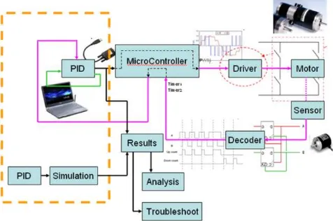
ince data collection and systems monitoring are vital in industrial environment, development of real time facilities for control systems has become needy for engineers and technologist. As such, this paper focuses on the real time development of DC motor drive systems. According to [1], a cascade control of DC motor is the most effective for DC drives as it uses fast inner current loop and enclosed by outer speed loop. However, for industrial needy such as robotics arm or pick and place systems, it is desired to attach position loop to the system. Therefore, this paper proposed a newly implemented real time cascade control system without inner current loop as shown in Fig. 1.
The system consists of primary and secondary loop
so-called speed and position loop respectively. All variables
abbreviated as CO2, PV2, PV1 and SP1 represent secondary control output, secondary process variable, primary process variable and primary set point respectively. Note that D2 represents a disturbance that impacts the PV2 before they impact PV1. Fig.2 shows the system configuration where PIC microcontroller from Microchip is used to build the decoder.
Mazree Ibrahim and Sy. Najib Sy. Salim are with department of Control, Instrumentation and Automations, Universiti Teknikal Malaysia Melaka, Malaysia. (email: [email protected] and [email protected])
M. Nizam Kamarudin is with department of Power Electronics and Drives, Universiti Teknikal Malaysia Melaka, Malaysia. (email: [email protected])
Aminurrashid Noordin is with department of Mechatronics, Universiti Teknikal Malaysia Melaka, Malaysia. (email:[email protected])
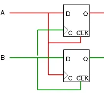
The purpose of decoder is to decode signal from rotary encoder. The outputs of the rotary encoder are sets of pulses train. Specifically, the decoder is named quadrature decoder [2].
Fig. 1. Cascade control of DC motor with inner speed and outer position loop
Fig. 2. System configuration
II. DC MOTOR MODEL
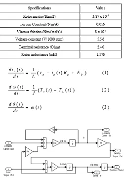
A separately excited DC motor is used because it has an independent voltage supplies to the field and armature windings. This type of structure gives advantage of more control over the motor performance [1]. A brushed M586TE motor manufactured by McLennon is used in this project. The parameters are listed in Table 1. Motor back emf and load torque makes the motor equation non-linear. As such, the state space equations (1), (2) and (3) is derived to provide the simplicity of modeling task. The model is depicted in fig. 3.
Real Time Cascade PI Control for Position Monitoring of DC
Brushed Motor
Mazree Ibrahim, Sy. Najib Sy. Salim, M. Nizam Kamarudin, Aminurrashid Noordin
TABLE I DC MOTOR PARAMETERS
Specifications Value
Rotor inertia (Kgm2) 3.87 x 10⁻⁵
Torque Constant (Nm/A) 0.056
Viscous friction (Nm/(rad/s)) 8 x 10⁻⁶
Voltage constant (V/1000 rpm) 5.56
Terminal resistance (Ohm) 2.40
Rotor inductance (mH) 1.576
Fig. 3. DC motor model
III. CONTROLLER DESIGN
During the real time implementation phase, a simulation of overall system is developed beforehand. The simulation model is used to preliminarily tune inner speed loop controller as well as the outer position loop controller. Paper [3] provides procedure for cascade control tuning method where it mentions that for any multi-loop control scheme, the dynamics of all loop need to be taken into account while designing a controller. For this system, a proportional – integral (PI) controller is employed for both speed and position controllers because of several practical advantages. PI controller offers simple structure as well as robust performance [1]. The speed of the motor is actually controlled by adjusting the width of the pulse width modulation (PWM) signal through the power switching devices in the DC/DC converter circuit. Therefore, the use of derivative term for motor drive which equipped with DC/DC converter is unnecessary as some signals will have discontinuities or ripple that would result in spikes when being differentiated [4].
Equations (4) and (5) explain PI controller mathematically while fig. 4 shows a model of PI controller in SIMULINK environment. The overall model of the system is illustrated in fig. 5
Fig. 4. Digital PI Controller
IV. SYSTEM IMPLEMENTATION
The actual system is shown in fig. 5. The system is equipped with motor driver circuit, encoder and decoder circuit. A PIC from Microchip is used to build the decoder which decodes a pulses train from rotary encoder. Specifically, the decoder is named quadrature decoder shown in fig. 6. This circuit is taken from “AN718: Brush-DC Servomotor Implementation using PIC17C756A” [5].
Fig. 6. Simple quadrature decoder using flip-flop
H-Bridge DC-DC converter drives the motor forward and reverse. Besides, it realizes 4 quadrant operations for braking and motoring function. In the simulation phase, the DC-DC converter is modeled in SIMULINK as it is non-linear due to
their inherent switching operation [6,7]. In real time
implementation, the regulation of the speed and position is achieved by the pulse width modulation (PWM) technique. The PWM switch the power MOSFET ON and OFF. As such, speed is varied by controlling the ON time of the pulse. As the position is obtained by integrating the speed with time, it is therefore possible to control the position of the DC motor by controlling the speed at a very first time. The correct selection of power semiconductor devices for the drive circuit is vital to ensure nearly perfect systems. The MOSFET is used based on its low switching loss and it’s also could be operated in frequency more than 1 Mega Hertz [1]. A graphical user interface (GUI) for the system is developed in C# environment. The GUI is shown in fig. 7.
Fig. 7. User interface appear on host PC.
The parameter of the PI controller is tuned using Zigler-Nichols method. In the cascade control system, an inner loop is tuned first before the outer loop is engaged [1]. The parameters determine the transient response of the system such as rise time and settling time. The integral gain on the other hand ensure low steady error [8] while the value of proportional gain is constrained to from further increase to avoid the closed loop system become unstable.
V. RESULT
The system performance is measured by testing the system with various demanded input. The most satisfactory control parameters are listed in table 2 whereas table 3 shows the experimental result.
TABLE 2 CONTROL PARAMETERS
Parameters Controller (Speed)
Controller (Position)
Kp 1.7 24.8
Ki - 30
TABLE 3
MAPING OF REAL TIME INPUT – OUTPUT POSITION
Demand position
Actual Position Absolute error
no load with load
no load
( % )
with load
(%)
45° 44.64° 45.73° 0.8 1.62
90° 89.64° 91.68° 0.4 1.87
135° 135.01° 136.56° 0.01 1.16
180° 181.66° 176.56° 1.98 1.91
225° 227.16° 221.67° 0.96 1.48
270° 272.38° 274.4° 1.73 1.63
315° 312.48° 317.72° 0.8 0.86
360° 357.4° 357.2° 1.83 0.78
Fig. 8 and fig. 9 show a response for demanded 90° position for no-load and without load respectively. Ideally, the system reaches demanded position at 0.2 seconds. Slight delay occurred when the load is attached to the system as it reached demanded position at 4 seconds. Moreover, the system with load suffered 37.2% overshoot as well as sluggish settling time in the transient start up. This phenomenon happened because starting a large motor is determined not only by the torque, but also by the inertia of the rotor coupled with load. inertia of the rotor.
Fig. 9. Position with load
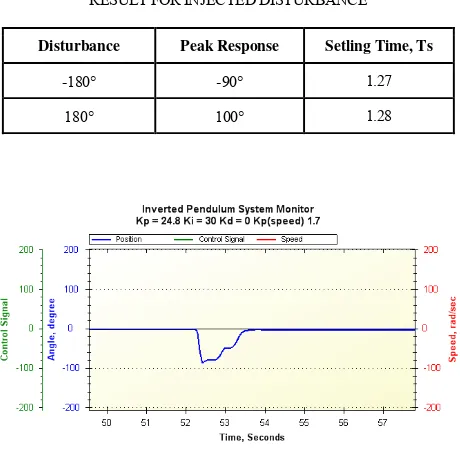
The system is injected with -180° and 180° during steady state running at 0°. Result shown in fig. 10 and fig. 11 indicate that the system managed to recovered as soon as 1.27 seconds and 1.28 seconds respectively. The algorithm managed to avoid disturbance when it can ensure that the peak response below than applied disturbance. The result is tabulated in table 4.
TABLE 4
RESULT FOR INJECTED DISTURBANCE
Disturbance Apply
Peak Response Setling Time, Ts (s)
-180 -90 1.27
180 100 1.28
Fig. 10. Disturbance at -180°
Fig. 11. Disturbance at 180°
VI. CONCLUSION
In this paper, the real time cascade PI control for position monitoring of DC brush motor was considered. A state space equation was derived to provide the simplicity of modeling task and had been used to facilitate the controller design. The experimental apparatus was constructed and the controller with GUI was implemented. An experimental result was presented to demonstrate the effectiveness of the designed controller.
From the result, it was concluded that the newly implemented real time cascade control without inner current loop perform as good as the conventional cascade control. The system tries to recover when the system is injected with external interruption making the system insensitive to disturbance. However, several improvements can be pondered to improve the transient.
ACKNOWLEDGEMENT
Part of this work is sponsored by short research grant under the faculty of Electrical Engineering in the Universiti Teknikal Malaysia Melaka, Malaysia.
REFERENCES
[1] M. Nizam. Kamarudin and Sahazati Md Rozali, “Simulink Implementation of Digital Cascade Control DC Motor Model – A Didactic Approach”, in 2nd IEEE International Conference on Power and Energy (PECon 08), December 1-3, 2008, pp. 1043 – 1048. [2] Sy. Najib Sy Salim, E.C Sai Hoo, Sahazati Md. Rozali, Herman
Jamaluddin, M. Khairi Aripin, “Cascade PI Control of an inverted Pendulum Using C# With Knowledge Base”, in Proceeding of MUCEET2009, June 20-22, 2009.
[3] Sanford Miles Dickert, “Development of High Bandwidth Torque Sensor for Control of High Performance Manipulator”, a thesis submitted to the Department of Electrical Engineering of Stanford University, March 1999.
[4] Burak Ozpineci, Leon M.Tolbert, “Simulink implementation of induction machine model – A modular approach,” in Electric Machines and Drives Conference (IEMDC'03), IEEE International 2003, Vol.2, June 2003, pp. 728 – 734.
[5] Microchip (1999). AN718: Brush-DC Servomotor Implementation using PIC17C756A. Microchip Technical Brief.
[7] Seah Chze Eng and Ramesh Oruganti, “An Automated Algorithm for Small Signal Analysis of DC-DC Power Converters”, in IEEE Transaction on Power Electronics, Vol. 11, No. 1, January 1996. [8] C.K. Lee and W.H. Pang, “Adaptive Control to Parameter Variations in
a DC Motor Control System Using Fuzzy Rules”, in Second International Conference of Intelligent Systems, 1994, pp. 247-254.
Mazree Ibrahim(M’09) was born in Kedah, peninsular Malaysia in 10th December 1974. The author obtained M.Sc in Automation and Control from University of Newcastle Upon Tyne, United Kingdom in 2008. The author became a Member (M) of IEEE in 2009.
He has 8 years experience in industry such as Acer Technologist (M) Sdn Bhd, Comag USA (M) Sdn Bhd, Intel Technology (M) Sdn Bhd and Texas Instrument Sdn Bhd. He currently attached in department of Control, Instrumentation and Automation, Universiti Teknikal Malaysia Melaka (UTeM).
Sy. Najib Sy. Salim, (M’08) was born in Kuala Lumpur, peninsular Malaysia in 10thMay 1973. The author obtained M.Eng in Electrical from Universiti Teknologi Malaysia, Malaysia in 2003. The author became a Member (M) of IEEE in 2008.
He used to be a Research Officer in Universiti Teknologi Malaysia as well as Assistant Engineer in SHIMANO (M) Sdn Bhd. He also has experience in teaching and learning activities where he had worked as a lecturer in Institute of Industrial Technology before being a senior lecturer in department of Control, Instrumentation and Automation, Universiti Teknikal Malaysia Melaka (UTeM).
M. Nizam Kamarudin,was born in Selangor, peninsular Malaysia in 10th January 1979. The author obtained M.Sc in Automation and Control from University of Newcastle Upon Tyne, United Kingdom in 2008.
He worked as a Technical Engineer in Magnetron Department, Samsung electronics (M) Sdn Bhd for 2 years. He currently attached in department of Power Electronic and Drives, Universiti Teknikal Malaysia Melaka (UTeM).
Aminurrashid Noordin, (M’09) was born in Pahang, peninsular Malaysia in 20th January 1979. The author obtained M.Eng in Electrical (Mechatronics and Automatic Control) from Universiti Teknologi Malaysia, Malaysia in 2009. The author became a Member (M) of IEEE in 2009.