STABILIZATION CONTROL OF ROTARY INVERTER PENDULUM SYSTEM WITH DOUBLE-PID AND LQR CONTROLLER
PANG KEE KIAT
A report submitted in partial fulfillment of the requirements for the degree of Mechatronics Engineering
Faculty of Electrical Engineering
UINIVERSITI TEKNIKAL MALAYSIA MELAKA
“ I hereby declare that I have read through this report entitle “Stabilization Control of Rotary Inverted Pendulum with Double-PID and LQR Contrroller” and found that it has comply the partial fulfillment for awarding the degree of Bachelor of Mechatronics Engineering.”
Signature : ...
Supervisor’s Name : Dr Chong Shin Horng
I declare that this report entitle “Stabilization Control of Rotary Inverted Pendulum System with Double-PID and LQR Controller” is the result of my own research except as cited in the references. The report has not been accepted for any degree and is not concurrently submitted in candidature of any other degree.
Signature :
Name :
ACKNOWLEDGEMENT
In preparing this report, I have met with many researchers, academicians and friends. They have contributed towards my understanding and thought. In particular, I wish to express my sincere appreciation to my project supervisor, Dr. Chong Shin Horng, for encouragement, guidance, advice and friendship.
I am also very thankful to researchers in Motion Control Lab, Fakulti Kejuruteraan Elektrik (FKE), Universiti Teknikal Malaysia Melaka (UTeM), Hee Wai Keat and Vasanthan A/L Sakthivelu for their advices and motivation. Without their continued support and interest, this project would not have been same as presented here. Lab assistant of Motion Control Lab and lab assistant of CIA Lab, FKE, UTeM, Khairulddin Hashim and Mohamed Khairy bin Ali should also be recognized for their support.
ABSTRACT
ABSTRAK
TABLE OF CONTENT
CHAPTER TITLE PAGE
1 2 3 4 ACKNOWLEDGEMENT ABSTRACT
LIST OF CONTENT LIST OF FIGURES LIST OF APPENDICES
INTRODUCTION
1.1 Research Background
1.2 Motivation and Significance of Research 1.3 Problem Statement
1.4 Objectives 1.5 Scopes
LITERATURE REVIEW
2.1 Theory and Basic Principle of RIP System 2.2 Review of Previous Relative Works 2.3 Summary and Discussion of the Review
MODELING AND CONTROLLER DESIGN 3.1 Experiment Setup
3.2 Modeling of RIP System 3.3 Controller Design Procedure
RESULTS OF STABILIZATION PERFORMANCE
5
4.2 Stabilization Performance of RIP System with Double-PID with LQR Controller
CONCLUSION AND FUTURE WORK 5.1 Conclusion
5.2 Future Work
25
31 31 32
REFERENCES APPENDICES
LIST OF FIGURES
FIGURE TITLE PAGE
2.1 2.2 2.3 2.4 2.5 2.6 3.1 3.2 3.3 3.4 3.5 3.6 4.1 4.2 4.3 4.4 4.5 4.6 4.7
TERASOFT Rotary Inverted Pendulum
Full State Feedback/LQR Controller Block Diagram 2DOF PID Controller
Model of cart inverted pendulum system with PID controller
Double-PID & LQR Control of Nonlinear Inverted Pendulum System
Connections between EMECS and host PC. EMECS Plant
Schematic diagram of DC motor of RIP system Mechanical Model of RIP
Block diagram of LQR controller in RIP system Block diagram of Double-PID and LQR controller Response of beta of all 9 trials of Taguchi Method
Response of beta and alpha of the RIP system with LQR controller
Graph of Sustained Oscillations of alpha when Ku=0.00007 Graph of alpha and beta after implementing PID_alpha into the RIP system
Graph of alpha and beta of the RIP system Graph of alpha stabilization performance Graph of beta stabilization performance
LIST OF TABLES
TABLE TITLE PAGE
3.1 3.2 3.3 4.1 4.2 4.3 4.4 4.5 4.6 4.7 4.8
System parameters for RIP system
L9 Orthogonal Array of Taguchi Method Ziegler-Nichols Tuning Rule of PID Controller Trials of values K using Taguchi Method Ground Tuned of PID_alpha Controller Fine Tuned of PID_alpha Controller PID_beta Controller.
Fine Tuned of PID_beta Controller
Summary of results of LQR and Double-PID with LQR controller
Repeatability test results of alpha Repeatability test results of beta
LIST OF APPENDICES
APPENDIX TITLE
APPENDIX A APPENDIX B
APPENDIX C
Trials of L9 Orthogonal Array of Taguchi Methods Repeatability Test on Stabilization Performance of Double-PID and LQR Controller
CHAPTER 1
INTRODUCTION
1.1 Research background
In this project, the stabilization controllers were proposed and compared by using the RIP system driven by servo motor module as a medium of experiment. The stabilization controllers that proposed in this project are double PID controller and LQR controller. Both designs of controller are compared with some specifications of performances.
1.3 Problem Statement
In order to control the stabilization of the RIP system at upright position driven by DC motor, many different controller approaches have been introduced in global academic researches. All of the approaches aim to achieve a better transient performance, low steady state error and low overshoot condition. The problem arises when there are two outputs giving feedback to control system, tuned signal is giving one input only back to the plant. This Single Input Multiple Output (SIMO) system cannot be controlled by a single conventional PID controller. Furthermore, certain parameter of RIP system is changed when disturbance is given to high non-linear characteristic of the RIP system. The single conventional PID controller cannot adapt to the changes of system parameter that occur on the system. Therefore, tuning multiple outputs of the RIP system at the same time become a challenge throughout the whole project. Double PID with LQR controllers are proposed to solve this SIMO RIP system.
1.4 Objectives
The basic objectives of this project are as follows:
a) To propose a double-PID with LQR controller for stabilization control of a rotary inverted pendulum system.
1.5 Scope
The scope of this project are:
a) The design of the stabilization controller for the RIP system is required to maintain the pendulum at upright position, within ±20º from vertical upright position.
b) After the pendulum is within ±5°, rotary arm of the RIP system is required to maintain moving range within ±22.5°.
c) The RIP system is modelled mathematically using Lagrange’s equation.
CHAPTER 2
LITERATURE REVIEW
2.1 Theory and Basic Principle of RIP System
Figure 2.1 shows the RIP system manufactured by TERASOFT. The RIP system is an under-actuated system which consists of one actuator and two Degree Of Freedom (DOF). The only actuator in the system is the DC motor. The rotary arm is driven by the DC motor where electrical energy is converted into mechanical energy, the torque to move it. The angular motion of the rotary arm gives energy to the pendulum to swing up and maintain stable at vertical upright position. The pendulum is set to be always perpendicular to the rotary arm. When the pendulum is at vertical upright position, the system is highly unstable, where a controller is needed to achieve stabilization and swing up mechanism of the RIP system. The amplitude of the supply voltage to the DC motor is proportional to the magnitude of the angular displacement of the rotary arm. Thus, the greater the supply voltage to the actuator, the greater the angular displacement of the rotary arm.
Figure 2.1: TERASOFT Rotary Inverted Pendulum
2.2 Review of Previous Related Works
There were many researchers studied RIP system from different aspects especially in modeling and designing different controller of the system. For stabilization and swing-up of RIP system, numerous designs of controller approach have been suggested to achieve better stabilization performance. Therefore, the study of research that had been done by other researchers is important to get a rough idea of designing controller in this RIP system.
There are basically divided to classical controller and advanced controller in proposed controllers to stabilize the RIP system. Proportional-Integral-Derivative (PID) controller is one of the most widely used controller in field of control engineering. As the RIP system is an underactuated and non-linear system, PID controller is common to be designed in the RIP system, as it improves overshoot percentage and steady state error of the system with an easy approach. PID controller can be used although mathematical model of the system is not known. When the mathematical model is not known, Ziegler-Nichols rules can be applied. Ziegler Nichols tuning rules give an educated guess for the parameter values and provide a starting point for fine tuning. Thus, from year 2009 to 2012, 2DOF PID or Double-PID was designed as a controller in the RIP system [6,8,11,13,15]. As a stabilization controller in the RIP system, the controller stabilized the inverted pendulum and as well as the rotary arm.
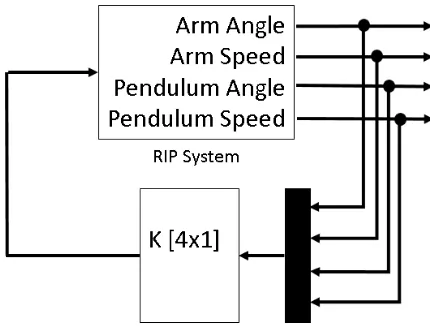
Figure 2.2: Full State Feedback/LQR Controller Block Diagram
Figure 2.2 shows a block diagram of a Full State Feedback (FSF) controller in the RIP system. The RIP system is was designed in state space model. Poles of the closed loop system may be placed at any desired locations by means of state feedback through an appropriate state feedback gain matrix K. There are a few approach to tune FSF controller, one of them is by pole placement method. According to M. Akhtaruzzaman [5], he designed FSF controller by placing stable poles of the RIP system, then used Ackermann’s formula and Integral of Time-weighted Absolute Error (ITAE) table, state feedback control gain matrix, K which is a × matrix was obtained. FSF controller was considered relatively ease of design and effective procedure to obtain the gain matrix K. There are some drawbacks of designing FSF controller. It requires successful measurement of all state variables or a state observer in the system, where it needs control system design in state space model. It also requires experienced researcher to determine the desired closed loop poles of the system, especially when the system has a higher order system than second or third order.
Proportional-Integral-Derivative (PID) Controller
Figure 2.4: 2DOF PID Controller [5]
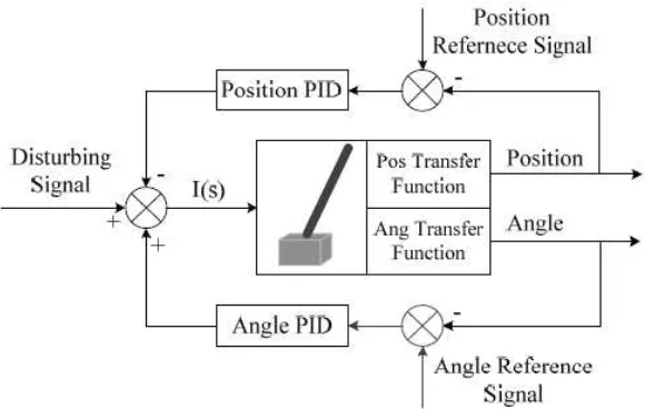
According to Figure 2.3, 2DOF PID was arranged cascaded. PID Arm was to maintain the rotary arm as zero, while PID pendulum maintained the speed and position of pendulum to remains stable [5]. PID Arm was tuned first then following by the PID Pendulum. Root locus analysis was used to tune the both PID.
Figure 2.4: Model of cart inverted pendulum system with PID controller
The performance of double-PID in stabilization of RIP system was not satisfactory as its dynamic responses is not robust. Thus, researchers suggested to implement hybrid strategy, combining LQR controller with double-PID controller as stabilization controller.
control law was derived. The results showed that the proposed adaptive PID sliding mode controller has succeeded to make the system stable and robust effectively. The main advantage of the proposed control method is that the PID controller gains can be obtained online and converge efficiently.
In year 2011, from the paper [7-8], the double-PID was suggested as a stabilization controller in RIP system. The fundamental of the design of double-PID controller is taking position of the cart and angle of the pendulum rod as signals for feeding back to the system as shown in
In paper [9], Gan designed a composite controller according to the characteristics of LQR and PID controller to get a faster control speed and better effect of dynamic balance. The results show that the control algorithm combined by LQR and PID can obtain a good balance effect and has a good anti-disturbance effects, which can restore dynamic fast. For the PID controller, it can control robot balance but the robot vibrate larger in the vicinity of balance point, the static performance is poor [9]. For the LQR controller, it has a good control effect in small-angle scope, but, for larger disturbance, then the angle beyond the linearization constraint conditions, the LQR controller do not have good control effect, even cannot keep robot balance [9].
Figure 2.5: Double PID & LQR Control of Nonlinear Inverted Pendulum System [7]
Linear Quadratic Regulator (LQR) Controller
By using modern control theory, the design of LQR controller is started by considering the first-order mathematical model of inverted pendulum system. By using linear quadratic control theory to design the control current signal, the pendulum rod can achieve a stable equilibrium point at upright position. According to the LQR optimal control law, its optimality is totally depended on the selection of Q and r, whereby Q and r are weighting matrixes that penalize certain states and control inputs of the system. The widespread method used to choose Q and r is by means of simulation and trial [10].
In paper [9], LQR controller is designed into a two-wheeled self-balancing robot. The results showed that an inverted pendulum system is unable to achieve the dynamic balance of the robot under the control of LQR. The limitations of LQR in a system are system modelling must be accurate and physical system parameters must be strict. In order to get faster control speed and better effect of dynamic balance, a composite controller is design according to characteristics of LQR and PID controller. Experiment summary in [9], the control algorithm combined by LQR and PID can obtain a good balance effect and has a good anti-disturbance effects and can restore dynamic fast.
In paper [11], the value of gain K is obtained by using the function lqr in MatLab. Furthermore, Taguchi Methods can be used to tune the gain K. The Taguchi methods are popular design of experiment (DOE) methods used in industry [11]. Due to the four gains in
K, an orthogonal array that can include at least four factors needed to be used and L9 orthogonal is chosen for tuning the gain K because this array allows four three-level factors at most [11]. In the conclusion [11], the L9 orthogonal array in Taguchi methods can tune the feedback gain of the controller efficiently, which means that the RIP system able to stable at upright position. Yet, from A. Khashayar [12], the LQR controller could not set the pendulum position to zero degree, the reference angle at upright position, when it is at non zero initial condition. Thus, there were researchers suggesting to implement a double-PID controller into the system.
Fuzzy Logic Controller
velocity of pendulum, that are read by two encoders in the system. The fuzzy logic controller requires experts’ previous experience about the operation of the real RIP system to create suitable experimental rules. The deviation on the angular displacement of pendulum from the reference angle is one of the input to the fuzzy logic controller, while the second input to the controller is angular velocity of the pendulum. These two inputs help the controller to diagnose how the motor decrease the angular position error to zero with rotating the rotary arm clockwise and anticlockwise repeatedly [13].
In paper [14], stabilization of RIP system is achieved by mapping linear optimal control law to the fuzzy inference system (FIS). A Mamdani FIS is designed which stabilizes the pendulum in the linear zone, emulating LQR control around the equilibrium point. The linear state feedback law is mapped to the rules of the fuzzy inference engine. The system consists of two fuzzy inference subsystems, one taking as inputs the angular position and speed of the pendulum arm, and other one taking as inputs the angular position and speed of the pendulum. The two output signals from both subsystems are then added to give a single control signal [14]. In the experiment, the observed performance of the system is smooth, and it is experimentally shown that the closed loop balancing system based on the fuzzy controller exhibits greater robustness to unmodeled dynamics and uncertain parameters than the LQR controller that it emulates [14]. Fuzzy logic controller requires complex linguistic expression. The linguistic expression which are the basic of the rule-base of the fuzzy logic controller must generated based on experts’ whom have done many relevant experiments.
2.3 Summary and Discussion of the Review
CHAPTER 3
MODELLING AND CONTROLLER DESIGN
3.1 Experimental Setup
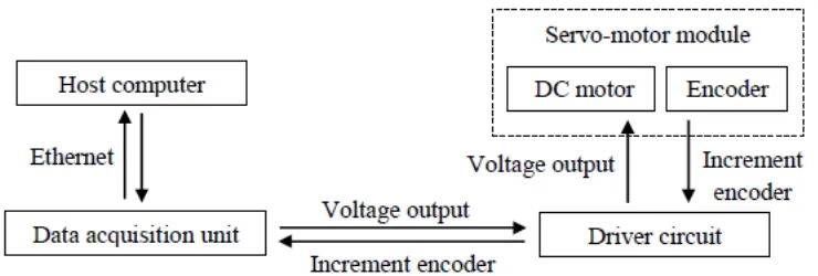
The RIP system setup requires two categories, which are host computer and Terasoft Electro-Mechanical Engineering Control System (EMECS). The EMECS is including three main components which are MicroBox 2000/2000C, servo-motor module, driver circuit and power supply. MicroBox 2000/2000C is a data acquisition unit to receive and send the signal via Ethernet cable connection with host computer. At the other end, the data acquisition unit interfaces with signal of rotary encoder of the system which has amplified by the driver circuit. According to Figure 3.1, the host computer is connected with each components in the system.
Figure 3.1: Connections between EMECS and host PC
host PC.
The Electro-Mechanical Engineering Control System (EMECS) plant shown in Figure 3.2 was set up.
Figure 3.2: EMECS Plant
3.2 Modeling of RIP system
The study of system dynamics resides in modelling its behaviour. Systems models are simplified, abstracted structures used to predict the behaviour of the studied systems. Our interest is pointing towards the mathematical model used to predict certain aspects of the system response to the inputs. In mathematical notations a system model is described by a set of ordinary differential equations in terms of state variables and a set of algebraic equations that relate the state variable to other system variables [15].
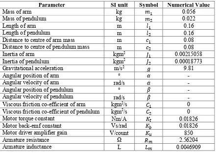
Parameter of RIP System
The RIP system is an electro-mechanical engineering control system. The involved parameters consists of electrical and mechanical parameters. Table 3.1 shows the parameters of the whole system.
Table 3.1: System parameters for RIP system
Parameter SI unit Symbol Numerical Value
Mass of arm kg 0.056
Mass of pendulum kg 0.022
Length of arm m 0.16
Length of pendulum m 0.16
Distance to centre of arm mass m 0.08
Distance to centre of pendulum mass m 0.08
Inertia of arm kgm2 0.00215058
Inertia of pendulum kgm2 0.00018773
Gravitational acceleration m/s2 9.81
Angular position of arm ° -
Angular velocity of arm rad/s -
Angular position of pendulum ° -
Angular velocity of pendulum rad/s -
Viscous friction co-efficient of arm kgm2/s 0
Viscous friction co-efficient of pendulum kgm2/s 0
Motor torque constant Nm/A 0.01826
Motor back-emf constant Vs/rad 0.01826
Motor driver amplifier gain V/count 850
Armature resistance Ω � 2.56204