Control of Automatic Food Drive-Through System using
Programmable Logic Controller (PLC)
M. Z. A Rashid, T. A. Izzuddin, N. Abas, N. Hasim, F. A. Azis and M. S. M. Aras
Universiti Teknikal Malaysia Melaka, Hang Tuah Jaya, 76100 Durian Tunggal,
Melaka, Malaysia
[email protected]
Abstract
This project is about automatic control for food drive through system controlled via Programmable Logic Controller (PLC) and this system consists of food drive through with two lanes and no human operator is required to operate this food drive through. The difference of this automatic control drive through system compared with the current drive through system is the current system required a few operators to operate the system. This automatic control drive through system is fully operated by machine, like order and payment machine and conveyor which deliver the food while human only needed and involved only to prepare the food. Since there are two lanes involved in this system, the machine installed has two order and payment machines, two ticket verification machines, two conveyors which connect to the kitchen and four sensors to detect the vehicles.
Keywords: Automatic Drive Through, Food, Programmable Logic Controller, Simulation
1. Introduction
Millions of people purchase fast food using drive through service every day. Besides of a lot of its advantages like this system is quite convenient, easy and fast, it also has become an important part of modern people to accomplish their on-the-go busy lives. This system allows users to stay inside their cars during bad weather and it also saves time. In the current system, customers would drive to a special lane where they would see a large board that displays various types of menus. They would line up to order through a microphone and pay at a booth with an attendant in it. After ordering, they would drive to the pickup area.
As a lot of people getting busier, food drive through system has became one of the popular service in food service industry. A lot of companies have been making huge profit by applying this service, for instant, Mcdonald and Rally’s. Today, even banking and grocery shopping sector like City Center Bank and Tesco involve in drive through service in some selected country.
The objectives of this project are summarized as follows (a) To design a new drive through system which involve two lanes where it can decrease the need of human as operator in new food drive through system. (b) To increase the efficiency of the new drive through system compared to the current food drive through system.
2. Motivation
Food drive through system started on 1941 where Carl Karcher, and his wife bought a hot dog cart and began serving customers curb side, so they wouldn't have to even get out of their cars. In 1948, Harry and Esther Snyder opened the first In-N-Out Burger in Baldwin Park, CA. The Snyder's concept was credited with being the first establishment to use a two-way intercom for customers to place their orders from a speaker stand, then pull up to a window, where they paid for and received their order. Furthermore, in 1975 McDonald's, opened its first drive-thru in Sierra Vista, AZ. McDonald's may have been late to the drive-thru part. Today, the average McDonald's sees 60% of their business generated in the drive-thru lane. The drive through system improved when HM Electronics developed the first wireless drive-thru intercom system in 1984. The wireless system allowed the order taker to move about the restaurant to draw beverages and pack orders, while still being able to communicate with the customer in an efficient manner, boosting productivity and reducing costs.
In the system done by [1], there were seven categories measured included in the study. All of these seven categories played an important role in order to determine the quality of a drive through system. The categories measured by [1] were; speed of waiting and service time, accuracy, speaker clarity, menu board appearance, customer service analysis, pre-sell menu board and lastly order confirmation board.
University of Virginia [2] developed touch screen drive through interface system which was designed to improve the drive through system at that time by using a touch screen interface instead of the voice system. The features of this touch screen drive through interface system were it had; (a) two screens. One screen would show a read-only current order and balance due. The second screen was a ‘touch screen’ that allows users to place, change, start over, and submit their order, (b) real-time updates where as customers perform their orders, the read-only “Current Order” screen would automatically update the balance due, and list the food item ordered, along with any customizations, (c) cancellations-where the customers could cancel any particular item they had ordered and also allowed users to omit any condiments they did not wish to be included in their meal, (d) accessing the “Current Order” screen where the users could modify their orders by accessing the “Current Order” screen through the “Change Order” button located on the bottom of the screen, (e) Order Screen- menu options that the fast food restaurant provides would be listed under different categories across the top of the screen and after the order was confirmed, the customer just need to push confirm button. Lastly the system had (f) Help Instructions - an assistance button is provided to allow users to speak with someone working inside the restaurant for help [2].
payment could be done once the order confirmed. In addition, in [4], the system in [3] was upgraded and improved in terms of user interface, traffic flow and login and payment.
Moreover, the system done by [5] paper established a new mobile electronic toll collection(m-ETC) by integrating mobile communication with radio frequency communication on microprocessor control with an e-commerce business model. It proposed to complete toll interaction on wireless environment and apply in freeway entrance gate control, freeway toll station control and parking lot.The car unit included identical electronic transceivers as Roadside transceiver and roadside receiver to interact with road side unit using a microprocessor. The roadside transceiver will transmit an interrogation message to activate the car unit to start the GSM handset for ETC electronic transaction. While the toll center accepted the transaction, the GSM handset will receive an approve code for the car unit. The car unit will acknowledge to roadside unit at appropriate instant of passing by the roadside receiver to complete the acknowledgement.
Another research done by [6] focused on Highway's Electronic Toll Collection System. This paper showed the composition and principle of ETC system. It also compared the design of vehicle's automatic identifying system. Main function of the system were divided into 3 categories, where there were information gathering and communication network function, billing and vehicle fee function, system and vehicle management function
System component consists of 3 parts; (a) Vehicle terminals-it was a data collection terminal and collection positioning data, (b) Center control- complete the decision making of system and center operation of banks – a simulated bank to charge once the order confirmed.
The system developed by [7] was the drive through banking system. This system was designed to eliminate undue time delay in the banking hall. It was a conveyer type drive through banking system. It basically employed a motoring system and control unit.
3. System Design
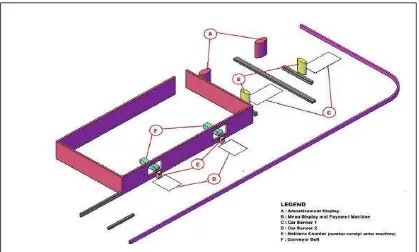
Figure 2. The Automatic Food Drive through System Display and Components
There are six components are needed to develop this automatic drive through system as depicted in Figure 2. The components of this system are; advertisement display, menu display and payment machine, car sensor 1, 2, 3, 4, retrieve counter and conveyor belt. This system also applied to the second counter which utilizes sensor 2 and 4 to conduct the detected process.
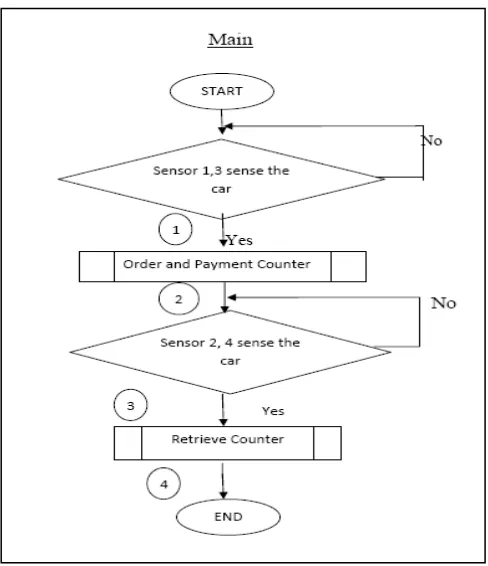
4. System Flowchart
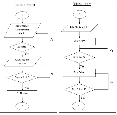
Figure 4(a). System Subroutine Flowchart for Order and Payment Inside Automatic Food Drive through System, Figure 4(b) System Subroutine
Flowchart for Retrieve Inside Automatic Food Drive through System
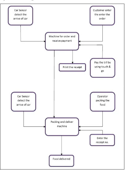
5. System Block Diagram
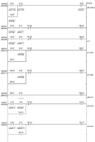
6. Programmable Logic Controller Ladder Diagram
Figure 6. Continue: PLC Ladder Diagram for Automatic Food Drive through System
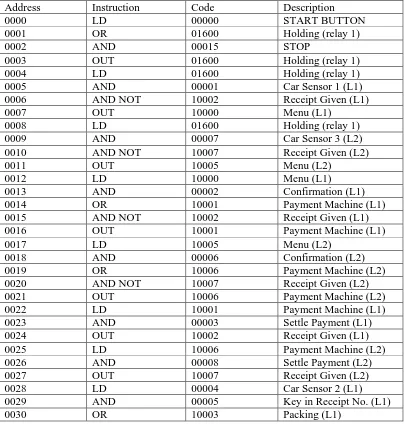
Table 1. Mnemonic Codes of PLC Controller for Automatic Food Drive through System
Address Instruction Code Description
0031 AND NOT 10004 Food Deliver (L1)
The PLC program for the system is shown in the Figure 6. Based on the PLC program of a drive thru system that has been created, there will be two different lanes. Firstly, the 00000 is the start button and 00015 is the stop button of the whole system. When the 00000 start button is pressed, the holding relay 01600 will be energized. Therefore, the normally open of the relay contact 01600 will close and form a holding circuit to kept the relay 01600 energized.
When the car sensor 1 of the first lane (contact 00001) detected a car, the screen showing the menu (10000) will turn on. After the customer finished selecting the menu he/she wants and pressed the confirm button (contact 00002), the payment machine (10001) will be turned on to enable the customer to make payment and hold the circuit with address line 000003. After the payment has been made, the relay 10002 will be energized. As the result, a receipt will be printed and the contact 10002 which is normally closed will become open to reset the order and payment machine of the first lane.
After finished order and payment, the car will go to retrieve counter. When the sensor 2 of the first lane (00004) detect a car, the customer is required to key in the receipt number at the retrieve counter. After the receipt number is inserted, the packing machine (10003) will started to pack and deliver the food to the customer via conveyor. When the customer retrieved the food, leave the retrieve counter and reached car sensor 3 (10003), relay 10004 will energized and reset the retrieve counter.
There will be the exactly the same process in the second lane as the first lane. When the car sensor 1 of the second lane (contact 00007) detected a car, the screen showing the menu (10005) will turned on. After the customer finished selecting the menu he/she wants and pressed the confirm button (contact 00006), the payment machine (10006) will be turned on to enable the customer to make payment and hold the circuit with address line 000004. After the payment has been made, the relay 10007 will be energized. As the result, a receipt will be printed and the contact 10007 which is normally closed will become open to reset the order and payment machine of the first lane.
8. Conclusion
In this new automatic food drive through system, it was divided into two parts, combination of order and payment counter and while another counter is retrieves counter. Based on the requirement, two lanes are designed to increase the efficiency of drive through system. There is one order and payment machine at each lane. Even though there are not in the same lane, the driver still can take their food at any of the retrieve counter after they have their order in any of the order and payment machine. The conveyor will deliver their food according to the numbers of recipe user enter. This is a simple drive through system by using the touch screen technology and the system is simulated using Programmable Logic Controller (PLC) OMRON CQM1H. The next stage for the research is to conduct the mathematical modeling for the system as mentioned in the [8-10] and a few other types of sensor and controllers can be explored and used as illustrated in the [11] and [12].
Acknowledgement
The authors want express appreciation to Universiti Teknikal Malaysia Melaka (UTeM) for sponsoring this project.
References
[1] QSR Drive-Thru Performance Study, Insura Research, Columbus, USA from http://
www.qsrmagazine.com/prdering/qsr-drive-thru-performance-study-methodology?microsite=5, (2011). [2] C. Thomas, J. Fleming, F. Hannaka, L. Song and M. Wong, “Touch Screen Drive-Thru Interface”, The
Department of System and Information Engineering, University of Virginia, Charlottesville, VA 22903, United States, (2011).
[3] B. Lam, J. Chui and T. Lui, “Wi-Fi Drive-Thru System-pass 1”, University of British Columbia, Canada,
(2008).
[4] B. Lam, J. Chui and T. Lui, “Wi-Fi Drive-Thru System-pass 2”, University of British Columbia, Canada,
(2008).
[5] C. E. Lin and L. Yan Bi, “Mobile Electronic Toll Collection for E-Commerce Application”, Department of aeronautics and astronautics, National Cheng kung University Tainan, Taiwan, School of e-commerce, South China University of Technology Guangzhou, (2008).
[6] G.-X. Xu, J.-H. Liu, H. Young Tao and X.-C. Li, “The Research and Development of the Highway's
Electronic Toll Collection System”, Liaoning Technical University, (2007).
[7] B. Daniel, “Construction of a Drive-Through Banking system”, Regent University College of Science and Technology.
[8] M. Z. A Rashid, M. S. M. Aras, A. M. Kassim, Z. Ibrahim and A. Jamali, “Dynamic Mathematical Modeling and Simulation Study of Small Scale Autonomous Hovercraft”, International Journal of Advanced Science and Technology, pp. 95-114.
[9] M. Z. Ab Rashid and S. N. Sidek, “Dynamic modeling and verification of unicycle mobile robot system”, 2011 4th International Conference On Mechatronics (ICOM) Kuala Lumpur, Malaysia, (2011).
[10] M. Z. A. Rashid, M. S. M. Aras, H. N. M. Shah, W. T. Lim and Z. Ibrahim, “Design and system parameter's validation of the unicycle mobile robot”, 2012 International Conference on Control, Automation and Information Sciences (ICCAIS) Ho Chi Minh, Vietnam, (2012).
[11] M. Aras, M. Shahrieel, S. S. Abdullah and S. S. Shafei, “Investigation and Evaluation of Low Cost Depth Sensor System Using Pressure Sensor for Unmanned Underwater Vehicle”, Majlesi Journal of Electrical Engineering, vol. 6, no. 2.