UNIVERSITI TEKNIKAL MALAYSIA MELAKA
DEVELOPMENT OF CONTROLLER FOR
BACK COVER ASSEMBLY STATION FOR
FLEXIBLE MANUFACTURING SYSTEM
USING PROGRAMMABLE LOGIC
CONTROLLER (PLC)
Thesis submitted in accordance with the partial requirements of the Universiti Teknikal Malaysia Melaka for the
Bachelor of Manufacturing Engineering (Robotic and Automation) with Honours
By
UTeM Library (Pind.1/2007)
UNIVERSITI TEKNIKAL MALAYSIA MELAKA
BORANG PENGESAHAN STATUS LAPORAN PSM
JUDUL:
DEVELOPMENT OF CONTROLLER FOR BACK COVER ASSEMBLY STATION FOR FLEXIBLE MANUFACTURING SYSTEM USING PLC.
SESI PENGAJIAN: SEMESTER 2 2007/2008
Saya AMINUDDIN BIN ABDUL WAHAB
mengaku membenarkan laporan PSM / tesis (Sarjana/Doktor Falsafah) ini disimpan di Perpustakaan Universiti Teknikal Malaysia Melaka (UTeM) dengan syarat-syarat kegunaan seperti berikut:
1. Laporan PSM / tesis adalah hak milik Universiti Teknikal Malaysia Melaka dan
penulis.
2. Perpustakaan Universiti Teknikal Malaysia Melaka dibenarkan membuat salinan
untuk tujuan pengajian sahaja dengan izin penulis.
3. Perpustakaan dibenarkan membuat salinan laporan PSM / tesis ini sebagai bahan
pertukaran antara institusi pengajian tinggi.
4. *Sila tandakan (√)
SULIT
TERHAD
TIDAK TERHAD
(Mengandungi maklumat yang berdarjah keselamatan atau kepentingan Malaysia yang termaktub di dalam AKTA RAHSIA RASMI 1972)
(Mengandungi maklumat TERHAD yang telah ditentukan oleh organisasi/badan di mana penyelidikan dijalankan)
(TANDATANGAN PENULIS) Alamat Tetap:
79, Kampung Barokhas, Mukim Belimbing Kanan, 06300 Kuala Nerang,
Kedah Darulaman
Tarikh: _______________________
(TANDATANGAN PENYELIA)
Cop Rasmi:
Tarikh: _______________________
FAKULTI KEJURUTERAAN PEMBUATAN
Rujukan Kami (Our Ref) : 9 MEI 2008
Rujukan Tuan (Your Ref):
Pustakawan
Perpustakaan Universiti Teknikal Malaysia Melaka (UTeM)
Taman Tasik Utama, Hang Tuah Jaya, Ayer Keroh, 75450, Melaka
Saudara,
PENGKELASAN LAPORAN PSM SEBAGAI SULIT/TERHAD
- LAPORAN PSM SARJANA MUDA KEJURUTERAAN PEMBUATAN (ROBOTIK DAN AUTOMASI): AMINUDDIN BIN ABDUL WAHAB
TAJUK: DEVELOPMENT OF CONTROLLER FOR BACK COVER ASSEMBLY STATION FOR FLEXIBLE MANUFACTURING SYSTEM USING PLC
Sukacita dimaklumkan bahawa tesis yang tersebut di atas bertajuk
“DEVELOPMENT OF CONTROLLER FOR BACK COVER ASSEMBLY STATION
FOR FLEXIBLE MANUFACTURING SYSTEM USING PLC” mohon dikelaskan
sebagai terhad untuk tempoh lima (5) tahun dari tarikh surat ini
memandangkan ia mempunyai nilai dan potensi untuk dikomersialkan di masa hadapan.
Sekian dimaklumkan. Terima kasih.
“BERKHIDMAT UNTUK NEGARA KERANA ALLAH”
Yang benar,
………..
AZRUL AZWAN BIN ABDUL RAHMAN
Pensyarah,
Fakulti Kejuruteraan Pembuatan
UNIVERSITI TEKNIKAL MALAYSIA MELAKA
Karung Berkunci 1200, Ayer Keroh, 75450 Melaka Tel : 06-233 2421, Faks : 06 233 2414
DECLARATION
I hereby, declare this thesis entitled “Development of Controller for Back Cover
Assembly Station for Flexible Manufacturing System Using Programmable Logic Controller (PLC)” is the result of my own research except as cited in the references.
Signature :……….
Author’s Name :……….
APPROVAL
This thesis submitted to the senate of UTeM and has been accepted as partial fulfillment of the requirements for the degree of Bachelor of Manufacturing Engineering (Robotic
and Automation) with Honours. The members of the supervisory committee are as follow:
………
(En. Azrul Azwan bin Abd. Rahman) Supervisor
DEDICATION
ACKNOWLEDGEMENTS
Alhamdulillah, I’m grateful that by the power of Allah, Most Gracious, Most Merciful, I managed to complete this project. I also want to thank my parents, who taught me the value of hard work by their own example. Both of them are my source of inspiration that lead me to working hard in gaining knowledge. I also would like to share this moment of happiness with all my friends that had help me in completing this project in one way or another.
I also would like to thanks my supervisor, En. Azrul Azwan b. Abd. Rahman from Manufacturing Engineering Faculty, UTeM for all his guidance and help throughout the entire time of this project being carried out. Without this guidance this project might not go as well as it is. The encouragement and motivation that was given to me to carry out my project work are greatly appreciated.
ii
ABSTRACT
ABSTRAK
iii
1.3.1. Assembly of Back Cover 1.3.2. PLC and Siemens PLC 1.3.3. Pneumatic System
v
5. RESULT AND DICUSSION 5.1 Result
5.2 Discussion
6. SUMMARY, CONCLUSION AND RECOMMENDATION OF FUTHER WORK
6.1 Summary 6.2 Conclusion
6.3 Recommendation For Further Work REFFERENCES
APPENDICES
Appendices A : Pneumatic Part Appendices B : Motor Part Appendices C: Sensor Part
Appendices D : PLC wiring diagram
76 76 77 92
vii
LIST OF FIGURES
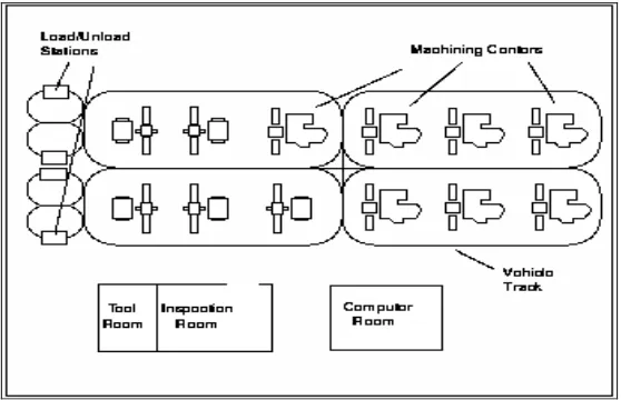
Figure 2.1: A Flexible Manufacturing System
Figure 2.2: Real FMS machining (FMS CAMOS II-MP) Figure 2.3: PLC connections
Figure 2.4: The separation of Controller and Process Figure 2.5: Relationship between PLC and Input/Output Figure 2.6: Basic PLC Operation
Figure 2.7: PLC connection to start and stop motor Figure 2.8: Push Button as a sensor
Figure 2.9: Motor Starter as an actuator Figure 2.10: Discrete Input
Figure 2.11: Example of Discrete Input Figure 2.12: Analog Input
Figure 2.13: Discrete Output
Figure 2.14: Example of Analog Output
Figure 2.15: Relationship between memory of PLC and Instruction Figure 2.16: Ladder Logic Diagram
Figure 2.17: Statement list
Figure 2.18: Function Block Diagrams
Figure 2.19: PLC scan
Figure 2.20: Software
Figure 2.21: Hardware Figure 2.22: Memory Size
Figure 2.23: Siemens PLC (Combining) Figure 2.24: LCD monitor
Figure 2.25: Inside CRT
Figure 3.1 : Back Cover assembly station
Figure 3.2: Main Component in Back Cover Assembly Station
Figure 3.3: Before-back cover separated with half assemble LCD monitor Figure 3.4: After-back covers have been snap fit with half assemble LCD monitor
Figure 3.5: Origin Back Cover
Figure 3.6: Feed the back cover by feeder module
Figure 3.7: Back covers lift up and will be transfer from station area to conveyor line area
Figure 3.8: Back cover transfer to the conveyor line area and snap fit with half assemble LCD monitor
Figure 4.1: Pneumatic Diagram
Figure 4.2: Connector Terminal Identification for CPU 226 AC/DC/Relay Figure 4.3: DC input card with 24VDC power supply
Figure 4.4: Output card wiring
Figure 4.5: Configuration for installations Figure 4.6: Electrical and pneumatic wiring Figure 4.7: Top View feeder module Figure 4.8: Side View feeder module
Figure 4.9: Feeder module assemble with cylinder Figure 4.10: Side View after assemble
Figure 4.11: Feeder module with Back Cover Figure 4.12: Vacuum part
Figure 4.13: Vacuum part assemble with fitting and vacuum pad Figure 4.14: Vacuum part assemble with station
Figure 4.15: Front View Vacuum part with station Figure 4.16: Front view DC motor mounting Figure 4.17: Top view DC motor mounting
Figure 4.18: DC motor mounting assemble with DC motor Figure 4.19: Side view DC motor with mounting
Figure 4.20: Configuration for connecting our personal computer to the CPU with the USB/PPI cable
Figure 4.21: USB/PPI cable
ix
Figure 4.22: Connection between USB/PPI cables with CPU PLC Figure 5.1: The controller of Back Cover Assembly station Figure 5.2: Functional block diagram network 1
Figure 5.3: Functional block diagram network 2 Figure 5.4: Functional block diagram network 3 Figure 5.5: Functional block diagram network 4 Figure 5.6: Functional block diagram network 5 Figure 5.7: Functional block diagram network 6 Figure 5.8: Functional block diagram network 7 Figure 5.9: Functional block diagram network 8 Figure 5.10: Functional block diagram network 9 Figure 5.11: Functional block diagram network 10 Figure 5.12: Functional block diagram network 11 Figure 5.13: Functional block diagram network 12 Figure 5.14: Functional block diagram network 13 Figure 5.15: Functional block diagram network 14 Figure 5.16: Functional block diagram network 15 Figure 5.17: Functional block diagram network 16 Figure 5.18: Functional block diagram network 17 Figure 5.19: Functional block diagram network 18 Figure 5.20: Functional block diagram network 19 Figure 5.21: Functional block diagram network 20 Figure 5.22: Functional block diagram network 21
LIST OF TABLE
Table 2.1: Reason and Explaining of the reason Table 4.1: Input Address and Address Description Table 4.2: Output Address and Address Description
1
CHAPTER 1
INTRODUCTION
Lately developers contesting to make the business or undertaking design automatically move. Either from the way that timber used is with implementation of Flexible Manufacturing System (FMS).
FMS is a manufacturing system in which there is some amount of flexibility that allows the system to react in the case of changes, whether predicted or unpredicted. This flexibility is generally considered to fall into two categories, which both contain numerous subcategories.
The first category, machine flexibility, covers the system's ability to be changed to produce new product types, and ability to change the order of operations executed on a part. The second category is called routing flexibility, which consists of the ability to use multiple machines to perform the same operation on a part, as well as the system's ability to absorb large-scale changes, such as in volume, capacity, or capability. The whole FMS is commonly controlled by a central computer.
The word of automation means the machines or equipment we require to automated are used the control system such as computer or other controller to control the machines and processes to replacing the human operator in industrial. The automation sometimes used to assist the human with the physical of work, it’s been greatly reduces the human sensory requirement. However, no device were created can match human eye in accuracy and precision in many task.
Currently, for manufacturing companies, the purpose of automation has changing from increasing productivity and reducing costs, to better range issues, such as increasing quality and flexibility in the manufacturing process.
In every automated machine we need the controller to control each process according our requirement. Specialized hardened computers, referred to as PLC, are frequently used to synchronize the flow of inputs from (physical) sensors and events with the flow of outputs to actuators and events. This leads to precisely controlled actions that permit a tight control of almost any industrial process.
Human-machine interfaces (HMI) or computer human interfaces (CHI), formerly known as man-machine interfaces, are usually employed to communicate with PLCs and other computers, such as entering and monitoring temperatures or pressures for further automated control or emergency response. Service personnel who monitor and control these interfaces are often referred to as stationary engineers.
3
1.1 Problem Statement
A recent trend in manufacturing industries is to make all process in manufacturing system is automated. All manufactures race to make their product high quality, to increase the productivity, to enhance the quantity, and to make their process flexible. Majority problem that face by product manufacturer is in assembly process product using operator assembler as which often foment in the quality. Problem that often face when using operator to assemble product is the quality produce did not keep customer needs. This may be due operator not very often is in deep comfortable position doing assembly process which job make over cause operator fatigue and could cause backache or more popularly known as musculoskeletal disorders (MSDs). In overcome this problem, most manufacture begins to look other alternative such as adaptation automation into each deep process in their product manufacturing. Additionally by using automation in the process their product can reduce especially cost of the labor. For adaptation deep automation their product's manufacturing process variety element should be considered like equipment use for automation stated process. Among the equipment often used currently is PLC, PLC is one device used to control process model which does neatly. Unlike general-purpose computers, PLC is designed with contains many input and output to be used to control many process without extended temperature ranges, immunity to electrical noise, and resistance to vibration and impact. The problem is to control the FMS system which needs deep expertise in installation programming of the PLC.
a) To automate the assembly station of the FMS system for LCD assembly.
b) To install and develop the programming for PLC to control the movement of FMS system.
1.3 Scope of Project
The aim of this project is to generate a controller device for FMS system. It consist of develop the programming for PLC that used to control the whole of FMS system which is assembly of back cover computer monitor. For this aim we should know of whole system stated FMS including of that FMS system, assembly of back cover monitor computer, PLC, pneumatic system, and the type of PLC we used. Below shown the element of the scope:
1.3.1 Assembly of Back Cover
a) Learn the sequence of the assembly process b) Identify the component used for this station
c) Identify input and output used and their address to communicate with PLC
1.3.2 PLC and Siemens PLC
a) Analyze the features and identify the components on PLC program. b) Study ladder diagram that being used in Siemens PLC
c) Learn the function of block diagram and learn how to program that being used as network program between PLC and the system.
d) Investigate and describe the function of each component or device in PLC such as timer, counter and relay.
5
a) Analyze the component of pneumatic in this system.
b) Investigate the features each pneumatic component to be used as input and output with PLC.
CHAPTER 2
LITERATURE REVIEW
This chapter will describes several literature reviews about the theory of FMS, its development, controller for FMS, theory of PLC, PLC component, PLC Siemens, and Liquid Crystal Display (LCD) monitor.
2.1 FMS
FMS is an integrated production system composed by a set of independent machining centers (MCs). An automatic part handling system (PHS) interconnects the MCs to a group of part-storage locations such as loading/unloading positions and input/output buffers. An automatic tool handling system (THS) interconnects the MCs to a group of tool-storage locations as tool magazines, tool rooms, exchangers and spindles. Either the PHS and THS mechanisms consist of one or more automated guided vehicles (AGVs) or transporters. A central supervisor (the FMS control software) monitors and manages the whole system. Three different kinds of object flows may be identified: the material flows (physical objects as parts, tools, pallets and fixtures), the information flows (abstract objects that describe the system status), and the decision flows (A. Anglani,2002)
7
FMS is a configuration of computer-managed numerical work stations where materials are automatically handled and machine loaded. The flexible manufacturing system is principally used in mid-volume (200 to 30,000 parts per year) mid-variety (5 to 155 part types) production. (Flexible Manufacturing, 2007]
2.1.1 FMS Components
Inside FMS system there were important components need to be known before we implement this system. Among component consist in FMS system is two or more computer-managed numerical work stations that perform a series of operations, an integrated material transport system and a computer that controls the flow of materials, tools, and information (e.g. machining data and machine malfunctions) throughout the system, and auxiliary work stations for loading and unloading, cleaning, inspection, etc. Figure 2.1 show the example of FMS and figure 2.2 show the real FMS machining process. (SNK Flexible Manufacturing System,2007)