M A T E R I A L S I N N E W Z E A L A N D
Manipulation of electrospun fibres in flight: the principle
of superposition of electric fields as a control method
A. H. Nurfaizey•J. Stanger•N. Tucker• N. Buunk•A. Wallace •M. P. Staiger
Received: 12 April 2011 / Accepted: 3 August 2011 / Published online: 13 August 2011
Springer Science+Business Media, LLC 2011
Abstract This study investigates the magnitude of movement of the area of deposition of electrospun fibres in response to an applied auxiliary electric field. The auxiliary field is generated by two pairs of rod electrodes positioned adjacent and parallel to the line of flight of the spun fibre. The changes in shape of the deposition area and the degree of movement of the deposition area are quantified by optical scanning and image analysis. A linear response was observed between the magnitude of movement of the deposition area and voltage difference between the auxil-iary and deposition electrodes. A squeezing effect which changed the aspect ratio of the deposition area was also observed to result from the application of symmetric electrical fields. Statistical analysis showed that the deflection and squeezing responses can be thought of as independent control actions. The results from this experi-ment suggest this particular application of superposition of electric fields could be used as to control the flight path of an electrospun fibre.
Introduction
Controlled deposition in electrospinning is conventionally obtained by passive means such as ‘‘window-frame’’ or gap spinning collectors, rotating drums, moving spinning heads or by shaping the electric field between the spinning head and the collector to influence the flight path of the fibre, or indeed by combinations of these methods. Despite a number of potential applications, controlled deposition has not been widely investigated. Bellamkonda et al. [1] claim a manufacturing technique for tissue scaffolds containing nanofibres with 75% oriented within 20 of an ideal
uni-axial orientation. A high degree of orientation is required to encourage cell migration into the scaffold and this orien-tation was achieved by spinning on to a rotating cylindrical mandrel. Recently, Wu et al. [2] described the process of producing small diameter 3-D nanofibrous tubular scaf-folds with controllable nanofibre orientations for vascular grafts. A rotating mandrel and two charged metallic plates were used to manipulate the electric fields for producing circumferential or axial oriented fibre.
The control of the flight path of electrospun fibres has long been industrially practiced to control the homogeneity of microstructure and the uniformity of fibre thickness [3]. Unlike laboratory scale electrospinning, industrial scale electrospinning machines are designed to raise fibre pro-duction levels to acceptably large rates, for example the NanoFMG Nanospinner 416 which has multiple delivery nozzles [4] and needleless designs such as the Elmarco Nanospider [5]. Although multiple jet electrospinning has a much higher output, the disadvantage of this approach is that the level of supervision and maintenance required to keep this type of machine running may be higher than single jet designs. In multiple jet electrospinning, the highly charged fibres are pushed away from each other due
A. H. Nurfaizey
Faculty of Mechanical Engineering, Universiti Teknikal Malaysia Melaka, 76100 Melaka, Malaysia
A. H. NurfaizeyJ. StangerM. P. Staiger (&)
Department of Mechanical Engineering, University of
Canterbury, Private Bag 4800, Christchurch 8020, New Zealand e-mail: [email protected]
A. H. NurfaizeyJ. StangerN. TuckerA. Wallace
The New Zealand Institute for Plant & Food Research Limited, Gerald Street, Lincoln 7608, New Zealand
J. StangerN. Buunk
to the repulsive Coulombic forces between the like charges [6, 7]. This means the areas of deposition have little overlap, and so do not interleave to produce uniform fibre deposition [3].
To improve the output quality in this type of production, various combinations of moving spinning heads and col-lecting substrates have been described in the production of Petryanov filters [3]. The methods include the use of spin-ning heads that scan across a moving collector, or collectors that move in two dimensions relative to the spinnerets [3]. However, as these industrial scale implementations use mechanical movement to achieve the desired degree of even deposition, it is satisfactory for achieving regular levels of deposition, but not for precisely manipulating the point of impact of the fibre with the collector.
A control strategy for electrospinning based on the use of a varying magnetic field to control an electrospinning fibre is unlikely to be successful. This is because the cur-rent flowing in the fibre is very low [8], and hence the force experienced by the fibre is also very low, and the accel-eration imparted to the relatively large mass of fibre will be correspondingly low. However, the force that can be applied by electrostatic means is clearly sufficient to form the fibre, and therefore it offers the possibility of in flight control of the fibres. Electrostatic fields can readily exert forces about five orders of magnitude greater than the magnetic field, and be varied with greater rapidity.
In a multiple field electrospinning system, the principle of superposition can be used to determine the net electric field in the system. The principle states that the net electric field produced at any point by a system of charges is equal to the vector sum of all individual fields, produced by each charge [9,10]. If a positive test chargeq0is placed near n point chargesq1,q2,…qn, the net electric field~E0at the test
charge point and the net electrostatic forceF~0acting on the
test charge are given by
E
Jets of fibre leaving the Taylor cone can be considered as a stream of charged particles travelling in an electric field towards a grounded collector. The introduction of auxiliary electrodes influences the existing electric field in the system and as charges exert attractive or repulsive forces one can potentially use this phenomenon as a control method. By varying the voltage difference of the auxiliary electrodes it is expected that the flight path of the fibres can be directed to move the point of deposition at will.
A certain amount of study on the use of electric fields to influence the flight path of fibres has been previously described. Jaeger et al. [11] devised a secondary ring electrode in an arrangement to spin fibre vertically down-wards. The secondary electrode was held at a ‘‘similar’’ voltage to the spinneret, and the formation of a fibre was initiated by gravity. Moving the secondary electrode rela-tive to the spinneret moved the site of onset of instability. The two electrode setup was used to produce orientated poly (ethylene oxide) fibres.
Deitzel et al. [12] also used poly(ethylene oxide) as a test material and further developed the Jaeger et al. [11] technique, basing the equipment on that used by Melcher and Warren [13] in an attempt to control the electrospin-ning process by influencing the shape and strength of the electrostatic field. A vertical spinning experimental set up was used with eight ring electrodes and the ability to charge the collector electrode. The charged collector electrode was used to increase the driving force exerted on the fibre, and the secondary electrode array was used as an electrostatic lens. This constrained the path of the fibre to the extent that the change of flight pattern associated with the onset of instability did not occur, and the area over which the fibre was deposited was reduced in size.
Bellan and Craighead [14] extended the notion of using an auxiliary electrode to constrain the flight path by devising a split ring electrode system with the intention of first constraining the beam, and cyclically varying the potential difference to cause the fibre flight path to scan to and fro on the collector electrode. High voltage relays were first used to give a step variation in the voltage, and a proportional system to allow faster variation of electrode voltage was then used to investigate the system response up to 1 kHz, allowing the production of aligned fibres.
A cylindrical coaxial secondary electrode surrounding either an array of spinnerets or a single spinneret has been used by Kim et al. [7]. This auxiliary electrode was at the same potential as the spinnerets to encourage the flight paths of the fibres to converge, thus reducing the area over which the fibre was deposited. Neubert et al. [15] describe an experimental set up using auxiliary electrodes in various forms and sizes, and their combinations to control the deposition area of both electrospinning and electrospray.
charges have significant influence on the degree of orien-tation of the fibre. Wu et al. [18] positioned an array of three rod electrodes behind a rotating collection mandrel. The centre electrode was held at a positive potential and the two outer electrodes at a negative potential; the spun material was negatively charged. Use of the array increased the degree of alignment of the collected fibres, and decreased the area over which the fibre was deposited. Carnell et al. [19, 20] used a single counter electrode, positioned behind a rotating collection mandrel set at an equal and opposite voltage to the spinneret. The fibre flight path was influenced to the degree of eliminating the bending instability to improve precision of deposition. Well aligned fibres were produced, and the spun mat was then repositioned at 90to the original orientation to
pro-duce a ‘‘pseudo-woven’’ mat with a 0/90layup.
There are also a number of patents describing the techniques of controlled deposition by means of electric fields manipulation. These include the use of an additional spinneret as counter electrode [21], a slatted or grooved belt collector [22, 23], and the use of reliefs on silicon wafer surface [24].
Although there have been promising results, most of the techniques are still lacking in the degree of control of the fibre in flight. In mechanical systems, the mass of a mechanical movement sets an upper limit to the frequency of response of the system. Although it is noted that mechanical movements can be used to achieve controlled manipulation of fibres if the spinning distance is reduced to a small number of millimetres [25], the deposition rate is correspondingly very low and the fibres are somewhat thick (about 500–750 nm) in electrospinning terms. If the limi-tations imposed by the inertia intrinsic in mechanical sys-tems could be overcome, the corresponding increase in precision of control would open up new areas of applica-tion for electrospun fibre products such as nano-scale rapid prototyping, specifically orientated fibre deposition for long nanofibre reinforced composites, or the production of fibre mats with tightly controlled pore size.
Before these possibilities can be realized, it is necessary to study and quantify the nature of the relationship between electric field manipulation and the magnitude of conse-quent fibre response. To our knowledge, there have been no reports on quantifying the nature and magnitude of this response. This article describes work done to quantify the magnitude of fibre response in flight to manipulation by an auxiliary electrical field. A conventional electrospinning set up was modified by the addition of auxiliary electrodes in the form of two sets of parallel rods. The design of the electrode system was inspired by the electrode configura-tions used to control arcing in high voltage switching gear [26]. The first system applying this technology is in com-mercial use to directly apply nanofibres to a filtration
substrate without the need for conversion from sheet stock or handling the nanofibres directly after deposition [26].
Experimental procedure
Electrospinning was carried out using an aqueous solution of poly(vinyl alcohol) (PVOH) (Chemiplas NZ limited, Wel-lington, NZ) with a final PVOH concentration of 8 wt%. The PVOH had an average molecular weight of 118,000 gmol-1 and degree of hydrolysis in the range of 85–90% (manu-facturer’s figures). The polymer solution was prepared by dissolving PVOH in distilled water for approximately 2 h at 60C, stirring at 500 rev/min using an overhead stirrer with
an impeller blade. To account for any loss of solvent during the mixing process, the polymer concentration was checked by drying a small sample in a convection oven at 80C. The
concentration of the stock solution was then adjusted with distilled water to the desired level.
All samples were electrospun at a potential difference of ?10 kV and working distance of 100 mm on a Model ES4 electrospinning machine (Electrospinz Ltd., New Zealand). The pressure of the polymer solution at the spinning head (varied by means of a gravity feed system) was used as the control variable. Once stable spinning was attained the pressure was kept constant. A grounded cleaned 300 mm square sheet of 316 stainless steel attached to the high density polyethylene backplane of the ES4 was used as the collector electrode. This electrode was then mounted with an A4 sheet of black 80 gsm Kaskad Raven Black 1516RB paper to collect the electrospun fibre. The two auxiliary electrodes were mounted as per Fig.1. These electrodes were held at a positive electric potential independent of the applied potential for electrospinning and of each other. The electric potential was varied between 0 kV (a grounded connection) to?12 kV as required for each experiment.
Results
It was observed that by varying the potential difference between the electrodes, the deposition area was moved in a controlled fashion. Depending on the voltages used, the spot moved along the x-axis (the axis of alignment of the electrode) in the direction away from the dominant elec-trode. For example, if the left electrode was charged at 2 kV and the right electrode was charged at 6 kV, the deposition area moved to the left as the result of higher repulsive force imposed by the right electrode. However, if both electrodes were charged at the same voltage the fibres were deposited at the middle of the axis. It was also noted that the introduction of a grounded auxiliary electrode did not affect the nature of the formation of the Taylor cone, the onset of instability or the shape and density of the deposited fibre mat.
The data were analysed to produce a graph of dis-placement in the xdirection varying as a function of the applied voltage (Fig.3). In the first experiment, both auxiliary electrodes were used—one was held at ground potential while the other was held at an applied voltage of ?2,?4,?6,?8,?10 or?12 kV. Initially, three samples were produced where both electrodes are held at ground potential and the average centre of these fibre mats is used as the origin for measuring displacement.
In the second experiment, the auxiliary electrodes were controlled independently. Three samples were produced for four treatments where the same applied voltage was applied to each electrode, i.e. 2/2, 4/4, 6/6 and 8/8 kV (written as left/right electrodes) giving a total of 12 sam-ples. Due to the symmetry of these applied fields and the 100 mm
100 mm
100 mm
75 mm 75 mm
AUXILIARY ELECTRODE
COLLECTOR
AUXILIARY ELECTRODE
Fig. 1 Plan view of electrode arrangement used to produce
electro-spun samples. Note the use of independent high voltage supplies and that electrodes are held at the same distance from the spinning tip as the collector
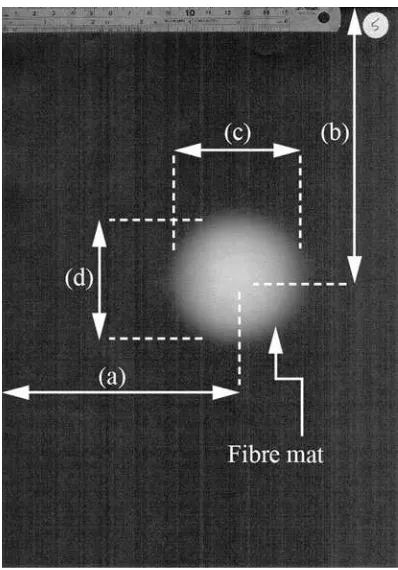
Fig. 2 Measurement positions of the samples: (a,b) are the distances
to the centre of the fibre mat in thexandydirections, and (c,d) the diameter of the fibre mat in thexandydirection
-30 -25 -20 -15 -10 -5 0 5 10 15 20 25 30
12 10 8 6 4 2 0 2 4 6 8 10 12
Applied V
o
ltage
[kV]
x Axis Deflection [mm]
Fig. 3 Experiment 1—deflection of electrospun fibre mat by an
small positional variation of the samples (a maximum of 4 mm), these sample positions were used to establish the origin for the deflection. Further samples were produced under the following conditions: 2/4, 2/6, 2/8, 4/6, 4/8, 4/10, 6/8, 6/10 and 8/10 kV which including reverse order gives a total of 18 additional sets of applied voltages. As each set of applied voltages was used to produce three samples— this gives a total of 66 samples. Figure4 shows the dis-placement in the x direction varying as a function of a pair of applied voltages.
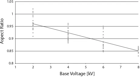
It should be noted that the strength of the symmetric applied fields did affect the aspect ratio of the deposited fibre mat. The aspect ratio was defined as the diameter of the oval fibre mat in thexdirection divided by the y direction diameter [ratio between (c) and (d) in Fig.2]. So an aspect ratio of less than 1 indicates the fibre mat is being squeezed between the two auxiliary electrode fields. Figure5shows the narrowing aspect ratio of the deposited fibre mat as the base voltage applied to the auxiliary electrode increases. The voltage applied to the auxiliary electrodes is considered to be made up of a base voltage and a voltage difference. The base voltage is the smaller of the two applied voltages. The voltage difference is the difference between the two applied voltages. So in the case of 2/6 kV, the base voltage would be 2 kV while the voltage difference would be 4 kV. In Fig.5, the line crosses they-axis at 1 which means that when both auxiliary electrodes are not charged the deposi-tion shape is perfectly round.
A comparison of the aspect ratio against the voltage difference gives no discernable relationship. The only relationship observed was that as the voltage difference increases the variability in observed aspect ratio decreases. Specifically, at zero voltage difference the variation ranges from the highest to the lowest observed aspect ratios. At the highest voltage difference the aspect ratio is within one decimal place of unity. However, this may be because there were fewer samples taken at the extremes of measurement.
These observations suggest that the effect of voltage dif-ference in the range examined has little effect on the aspect ratio of the electrospun fibre mat.
Discussion
In previous studies, electric field manipulation has been used to achieve some degree of controlled deposition by dampening the bending instability [7,11, 12,14,18–20]. This study, however, investigates the magnitude of move-ment of the deposited patch of fibre in response to a varying electric field without changing the bending insta-bility. To control the flight path of an electrospun fibre it is necessary to cope with considerable physical variation in the fibre itself during flight. The fibre starts life as a near stationary globule of dilute polymer solution. It is then drawn out into a stream of liquid which accelerates off into free space, solidifying into a gel and then a solid, so the dominant mechanical property becomes the modulus rather than viscosity. At some stage in flight the path of the fibre diverges from a straight path into an expanding helix, thinning beyond the point of naked eye visibility before finally impacting into the collecting surface and losing some degree of electrical charge. Although the fibre stream is highly charged at all stages of flight it does have a small but significant mass, and thus a degree of inertia to over-come when changing direction.
Therefore, due to these changes in state and mechanical and aerodynamic properties, concern arises in examining the data that there may be a non-linear response to the field applied. Performing a multi-factor polynomial regression analysis on all the data we found the introduction of second order terms were not significant (p[0.05). As such, a linear model is the most appropriate to explain the variance in the data.
x Axis Deflection [mm]
0
Fig. 4 Experiment 2—deflection of electrospun fibre mat by a pair of
auxiliary electrodes independently held at a pair of applied voltages. Linear trend (R2=0.90) is d= -1.789kV?0.36 where d is
deflection [mm] andkVis applied voltage [kV]
0.8
Fig. 5 Aspect ratio of electrospun fibre mat as a function of the base
voltage applied to two auxiliary electrodes. The aspect ratio is defined as thexdimension divided by theydimension. Base voltage is taken to be the lower of the two voltages applied to the two auxiliary electrodes. Linear trend (R2=0.65) is AR= -0.029kV?1.00
Experiment 1 was undertaken to determine the maxi-mum deflection that could be obtained with the described electrode geometry and a 10 kV electrospinning voltage. It was found using this arrangement that the average maxi-mum deflection was approximately 23.4 mm at an auxil-iary electrode potential of 12 kV. It should be noted that this limit is expected to be strongly dependant on the electrode geometry and the applied electrospinning volt-age. Experiment 2 was undertaken to determine if a base voltage would affect the deflection response due to a dif-ference in voltage. Specifically, is 4 kV applied to one electrode the same as 2/6, 4/8 and 6/10 kV where in each case the difference in voltage is always 4 kV?
The results in Figs.3and4 demonstrate that there is a linear response between the magnitude of movement of the deposition area and the applied auxiliary electric field. Deflection along thex-axis increases with the voltage dif-ference. The gradients suggest that for the arrangement used in this experiment every 1 kV of voltage difference will deflect the deposition area about 2 mm from the origin in the direction away from the dominant electrode (elec-trode which is charged at higher voltage). TheR2values of 97 and 90% suggest that the linear regression lines and the data are a good fit.
Due to the symmetry of the applied control field it was expected that the amplitude of the response would be equivalent regardless of which of the two electrodes was held at the deflection potential. However, as can be seen in Fig.3, samples were collected for both directions allowing us to test for the symmetry of the applied field. It was found that the field was not perfectly symmetrical. Within the limits of statistical significance (p\0.05) the gradients of a linear model fitted to either direction of response were equivalent, unlike the intercepts. The lack of symmetry was likely to be due to the imprecision inherent in the method of positioning the auxiliary electrodes (laboratory clamp stands). This is a limitation of the equipment available at the time and further studies with higher precision posi-tioning will be reported later. This should result in the same deflection response regardless of direction.
Experiment 2 also offered the opportunity to test if the two control fields, i.e. the difference in voltage for deflection and the base voltage for changing the aspect ratio of the deposited fibre matt, are independent of each other. Statistical analysis of the data from experiments 1 and 2 showed that within the limits of significance (p\0.05) the gradients of the deflection response were equivalent and that the intercepts were different. The dif-ference, however, is small (*4 mm) and is likely to be due to the difficulty in aligning a zero point on the substrate.
Performing a linear regression on the deflection as a response to the base voltage found no significant relation-ship (p[0.05). This implies that the base voltage has no
effect on the deflection of the fibre. Figure5demonstrates that the aspect ratio does show a linear response to the base voltage. This shows that the base voltage can be thought of as one control field that does not influence the other control field (voltage difference for deflection). Further, perform-ing a linear regression on the aspect ratio as a response to the difference in voltage shows no significant relationship (p[0.05). This demonstrates that not only does the base voltage not interfere with the deflection but that the dif-ference in voltage does not interfere with the aspect ratio. The two control fields are therefore independent in their action on the electrospun fibre in flight. In considering the control of the fibre in flight one can simply sum the effects of the different applied electric fields to reach the desired response within the limits of control. A final linear regression was performed on the off-axis deflections as a response to the deflection field and no significant rela-tionship (p[0.05) was found. Therefore, the deflection field only causes a response along the axis intended.
The ends of the auxiliary electrodes were rounded to remove the sharp edges. This geometry was chosen because charges spread more uniformly on curved surfaces compared to sharp edged surfaces [9]. The importance of the field strength along the axis of spinning for maintaining consistent electrospinning was considered when position-ing the auxiliary electrodes. If the electrodes are located too close to the collector, the resulting electric field in the vicinity of the collector makes the collector less attractive to the charged fibres. The auxiliary electrodes were posi-tioned at 75 mm from the collector so that the auxiliary electric field has minimum effect on the axis field strength, however, it still has sufficient influence on the deposition direction of the fibres. It was observed that the introduction of the auxiliary electrodes did not impede the natural occurrence of bending instability and most importantly, consistent electrospinning process was maintained.
The lower limits to the applied potential on the auxiliary were investigated. The introduction of a conductor at a potential of 0 kV might cause problems, as there is a possi-bility of this new conductor becoming the effective target electrode. To avoid this, we chose to keep our auxiliary electrodes at a distance of 100 mm (equivalent to the dis-tance between the Taylor cone and the collector). For the fibre to deposit on the auxiliary electrode it would either have to leave the Taylor cone at an angle of 90to the spinning tip
or travel a larger distance than to the grounded collector. The jet is unlikely to be ejected at a 90angle as surface tension in
a droplet with a Taylor cone shape would make it energeti-cally favourable to eject the jet from the top of the cone rather than the side. This is only true if the field conditions at 90to
When the auxiliary electrode was held at a potential above 14 kV fibre deposited on the auxiliary electrode. We are currently investigating the reasons for this and these results will be reported elsewhere. It is possible that this deposition pattern is because the auxiliary electrodes were acting as one side of a gap of the sort used in gap electrospinning [16,17,27]. A fibre will strike the earthed target and begin to be discharged while the following fibre section, still in flight will now experience an attraction to the auxiliary. Once it contacts the auxiliary it then becomes highly charged again and now is attracted to the collector. As the electric potential applied to the auxiliary increases, this process will become more prob-able resulting in more fibre being deposited on the aux-iliary electrode.
The results of this experiment are fundamentally useful in understanding the use of electric field manipulation as a control method. The technique can be used to predict the location and size of the deposition area of the electrospun nanofibres. Application of this method in mass production would enable the production of fibre mats with homoge-neous microstructure and uniform areal densities. One advantage of this technique is that it would allows for much quicker controlled manipulation of the charged jets [14] than established industrial techniques such as moving spinning heads and collectors [3]. As no moving parts are required, the speed of response of the system is only lim-ited by the speed at which the electrical field can be manipulated rather than the speed at which the mechanical assembly of spinning or collection by belt or drum can be physically moved.
However, the following limitations to the current state of the art should be noted. Although the method can influence the geometry of the deposited spot, it cannot yet focus the spot to the degree required to manipulate the position of an individual fibre. There are also certain limits to the voltage applied to the auxiliary electrodes to avoiding depositing directly onto the electrodes or reducing the driving potential to a sufficient degree to stop spinning. Further studies using this technique are ongoing and the results will be reported later.
Conclusions
The results from this experiment show that there is a relationship between the magnitude of movement of the deposition area and the applied auxiliary electric field. Voltage difference causes a linear response in the move-ment of the deposition spot but has no effect on the reduction of aspect ratio. On the other hand, base voltage does show a linear response to aspect ratio but has no effect on the deflection of the fibre. Statistical analysis confirms
that voltage difference and base voltage are independent in their action and therefore one can superimpose the effects of the different applied electric field to control the flight path of electrospun fibre. This study suggests that the principle of superposition of electric field could be used to control the flight path of electrospun fibre.
Acknowledgements This study was variously supported by the
Ministry of Higher Education of Malaysia, a Dick and Mary Earle Scholarship, a University of Canterbury Mechanical Engineering Premier Doctoral Scholarship, and by the New Zealand government through the Ministry of Science & Innovation (Contract C11X1001— Electrospun fibres for surface-active materials). Electrospinz Ltd, Blenheim kindly loaned certain pieces of equipment.
References
1. Bellamkonda RV, Kim YT, Kumar S (2006) United States Patent US20080208358, 7 Mar 2006
2. Wu HJ, Fan JT, Chu CC, Wu J (2010) J Mater Sci Mater Med 21(12):3207. doi:10.1007/s10856-010-4164-8
3. Filatov Y, Budyka A, Kirichenko V (2007) Electrospinning of micro and nanofibers: fundamentals and applications in separa-tion and filtrasepara-tion processes. Begell House Inc., New York 4. Anon (2011) Nanospinner 416. NanoFMG.http://www.nanofm
group.com/Nanospinner_eng.html. Accessed 17 Jan 2011 5. Petras D, Maly M, Pozner J, Trdlicka J, Kovac M (2010) United
States Patent US20100034914, 11 Feb 2010
6. Theron SA, Yarin AL, Zussman E, Kroll E (2005) Polymer 46 (9):2889-2899. doi:DOI10.1016/j.polymer.2005.01.054
7. Kim G, Cho YS, Kim WD (2006) Eur Polym J 42(9):2031. doi:
10.1016/j.eurpolymj.2006.01.026
8. Stanger J, Tucker N, Staiger MP, Kirwan K, Larsen N, Coles S, Jacobs D (2009) Solid State Phenom 151:54
9. Halliday D, Resnick R, Walker J (2001) Fundamentals of phys-ics, 6th edn. Wiley, Chichester
10. Nikitin K (2010)http://physics-help.info/physicsguide/electricity/ electric_field.shtml. Accessed 7 Feb 2011
11. Jaeger R, Bergshoef MM, Batlle CMI, Schonherr H, Vancso GJ (1998) Macromol Symp 127:141
12. Deitzel JM, Kleinmeyer JD, Hirvonen JK, Tan NCB (2001) Polymer 42(19):8163
13. Melcher JR, Warren EP (1971) J Fluid Mech 47(1):127143 14. Bellan LM, Craighead HG (2006) J Vac Sci Technol B
24(6):3179. doi:10.1116/1.2363403
15. Neubert S, Eblenklamp M, Pliszka D, Sundarrajan S, Rama-krishna S, Wintermantel E (2009) In: 11th international congress of the IUPESM. Medical physics and biomedical engineering. Springer Verlag, Munich
16. Li D, Wang Y, Xia Y (2003) Nano Lett 3(8):1167. doi:10.1021/ nl0344256
17. Liu L, Dzenis YA (2008) Nanotechnology 19:1. doi:10.1088/ 0957-4484/19/35/355307
18. Wu YQ, Carnell LA, Clark RL (2007) Polymer 48(19):5653. doi:
10.1016/j.polymer.2007.07.023
19. Carnell LS, Siochi EJ, Holloway NM, Stephens RM, Rhim C, Niklason LE, Clark RL (2008) Macromolecules 41(14):5345. doi:
10.1021/Ma8000143
20. Carnell LS, Siochi EJ, Wincheski RA, Holloway NM, Clark RL (2009) Scr Mater 60(6):359. doi:10.1016/j.scriptamat.2008. 09.035
22. Formhals A (1938) United States Patent US2109333, 22 Feb 1938
23. Kim HY, Park JC (2008) United States Patent US20080122142, 29 May 2008
24. Craighead HG, Kameoka J (2009) United States Patent US20090280300, 12 Nov 2009
25. Hellmann C, Belardi J, Dersch R, Greiner A, Wendorff JH, Bahnmueller S (2009) Polymer 50(5):1197. doi:10.1016/j. polymer.2009.01.029
26. Buunk N (2009) In: Tucker N (ed) Origins of the design of some secondary electrode systems for electrospinning control. Blen-heim (Unpublished results)