UNIVERSITI TEKNIKAL MALAYSIA MELAKA
EFFECTS OF WORKPIECE AND TOOL RIGIDITY ON
MACHINING PERFORMANCES
This report submitted in accordance with requirement of the Universiti Teknikal Malaysia Melaka (UTeM) for the Bachelor Degree of Manufacturing Engineering
(Manufacturing process) (Hons.)
by
MOHD ZAID BIN AWANG
B 050910295
880217-11-5537
________________
NAMA PENYELIA Pensyarah,
Fakulti Kejuruteraan Pembuatan
NOTA: BORANG INI HANYA DIISI JIKA DIKLASIFIKASIKAN SEBAGAI SULIT DAN
TERHAD. JIKA LAPORAN DIKELASKAN SEBAGAI TIDAK TERHAD, MAKA
BORANG INI TIDAK PERLU DISERTAKAN DALAM LAPORAN PSM.
UNIVERSITI TEKNIKAL MALAYSIA MELAKA
BORANG PENGESAHAN STATUS LAPORAN PROJEK SARJANA MUDA
TAJUK: EFFECTS TO WORKPIECE AND TOOL RIGIDITY ON MACHINING PERFORMANCES
SESI PENGAJIAN: 2012/13 Semester 2 Saya MOHD ZAID BIN AWANG
mengaku membenarkan Laporan PSM ini disimpan di Perpustakaan Universiti Teknikal Malaysia Melaka (UTeM) dengan syarat-syarat kegunaan seperti berikut: 1. Laporan PSM adalah hak milik Universiti Teknikal Malaysia Melaka dan penulis. 2. Perpustakaan Universiti Teknikal Malaysia Melaka dibenarkan membuat salinan
untuk tujuan pengajian sahaja dengan izin penulis.
3. Perpustakaan dibenarkan membuat salinan laporan PSM ini sebagai bahan pertukaran antara institusi pengajian tinggi.
4. **Sila tandakan (√)
SULIT
TERHAD
TIDAK TERHAD
(Mengandungi maklumat yang berdarjah keselamatan atau kepentingan Malaysiasebagaimana yang termaktub dalam AKTA RAHSIA RASMI 1972)
(Mengandungi maklumat TERHAD yang telah ditentukan oleh organisasi/badan di mana penyelidikan dijalankan)
Alamat Tetap:
NO. 37, LORONG SENTOSA 2 KG TENGAH (F) NERAM SATU 24060 KEMAMAN, TERENGGANU
Tarikh: 3.JUNE. 2013
Disahkan oleh:
Cop Rasmi:
Tarikh: 3.JUNE. 2013
DECLARATION
I hereby declare that this report entitled “Effects of Workpiece and Tool Rigidity on Machining Performances” is the result of my own research except as cited in the references.
Signature : ……….
Author’s Name : Mohd Zaid Bin Awang
APPROVAL
This report is submitted to the Faculty of Manufacturing Engineering of UTeM as a partial fulfillment of the requirements for the degree of Bachelor of Manufacturing Engineering (Process) (Hons.). The member of the supervisory is as follow:
………
i
ABSTRAK
ii
ABSTRACT
iii
DEDICATION
iv
ACKNOWLEDGEMENT
v
TABLE OF CONTENT
Abstrak i
Abstract ii
Dedication iii
Acknowledgement iv
Table of Content v
List of Tables viii
List of Figures x
List Abbreviations, Symbols and Nomenclatures xiii
CHAPTER 1: INTRODUCTION 1
1.1 Background 1
1.2 Problem statement 3
1.3 Objectives 3
1.4 Scope of the research 3
CHAPTER 2: LITERATURE REVIEW 4
2.1 CNC Milling 5 axis operation 4
2.1.1 Type of CNC Milling 5 Axis two general groups 4
2.2 Half Sphere Milling 5
2.3 Strategy in Half Sphere Milling – Zig zag 7 2.4 Consideration Material in Machining 8
2.4.1 Aluminium 8
2.4.2 Tool Steel 9
2.5 Machining Performance 11
2.5.1 Surface Roughness 11
2.5.2 Vibration Assisted machining 13
vi
CHAPTER 3: METHADOLOGY 16
3.1 Introduction 16
3.2 Flow chart process 17
3.3 Process Planning 18
3.3.1 CATIA – Design Modelling 18
3.3.2 Create of half Sphere using CATIA Software 19
3.3.3 Detail Drawing and Dimension 20
3.4 Machining Process (CAM) 21
3.4.1 Drawing stock 21
3.4.2 Describes Milling Machine – CNC Milling 5 axis 22
3.4.3 Describes Axis 23
3.4.4 Describes cutting tool 23
3.4.5 Describes tool path 24
3.4.6 Determine generate NC code 25
3.4.7 Setup on CNC Milling Machine 26
3.4.8 Strategy Milling Technique 27
3.5 Performance Measurement 29
3.5.1 Surface roughness 30
3.5.2 Vibration amplitude machining 31
3.5.3 Tool wear 32
3.6 Machining Parameters 33
3.7 Analysis 34
vii
CHAPTER 4: RESULT AND ANALYSIS 35
4.1 Surface Roughness 36
4.1.1 Result 36
4.1.2 Discussion 39
4.2 Vibration Amplitude Machining 41
4.2.1 Result 42
4.2.2 Discussion 45
4.3 Tool wear 49
4.3.1 Result 49
4.3.2 Discussion 51
4.4 Statistical of Analysis data on Aluminium 53 4.4.1 Objective of Optimization 53
4.4.2 Validation 55
4.5 Statistical of Analysis data on Tool Steel 56 4.5.1 Objective of Optimization 57
4.5.2 Validation 58
CHAPTER 5: CONCLUSION AND FUTURE WORK 60
5.1 Conclusion 60
5.2 Future work 61
REFERENCES 62
APPENDICES
viii
This general characteristic of Aluminium alloy Tool Steel of Mechanical properties
This is machining parameters in machining process
Average reading a surface roughness by Aluminium on normal technique
Average reading a surface roughness by Tool Steel on normal technique
Average reading a surface roughness by Aluminium on tool damping technique
Average reading a surface roughness by Tool Steel on tool damping technique
Average reading a surface roughness by Aluminium on workpiece damping technique
Average reading a surface roughness by Tool Steel on workpiece damping technique
Average reading a surface roughness by three technique on Aluminium
Average reading a surface roughness by three technique on Tool Steel
The result of average to vibration amplitude machining by aluminium
The result of average to vibration amplitude machining by Tool Steel
The average of measurement value to tool wear by Aluminium on three technique
ix 4.13
4.14
4.15 4.16
Design actual of response by Aluminium on the three technique The result of response evaluation by using Design Expert on Aluminium
Design actual of response by Tool Steel on the three technique The result of response evaluation by using Design Expert on Tool Steel
53
55 56
x
LIST OF FIGURES
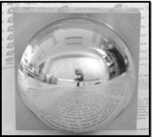
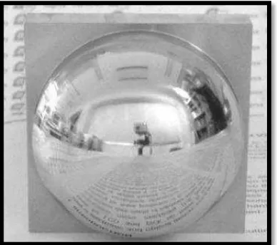
1.1 The half sphere modelling to produce 3 diamond mirror surface profile
2
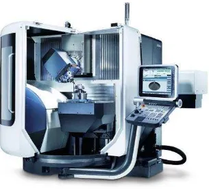
2.1 DMG DMU 50 Mono Block model of 5 Axis Milling operations 5 2.2 The expected of half sphere modelling on development 6 2.3
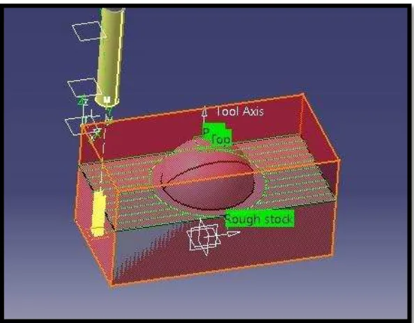
The CAD/CAM system used creates the 5 axis CNC part
programs, with the tool axis perpendicular to the surface Selection of tool path is zig –zag way
Aluminium Tool Steel
The schedule of evaluation measurement surface roughness The Accelerometer system to detect of amplitude machining performance.
Optical Microscopy structure on the tool wear The type of tool failure mechanism
6
3.3 Half sphere of dimension drawing on the actual modelling 20 3.4
Describe of the CNC milling 5 Axis
Illustration motion of CNC milling 5 Axis Machine Describe of define Axis reference
Define of tool selection using in machining programming Describe of tool path way
Define of data input ,output and NC coding
xi
Setup machining datum Normal technique machining Tool damping machining
Workpiece damping technique machining
Surface test device and testing measurement of surface roughness The scrip resulting after surface roughness measuring
Accelerometer device and located a probe by area position The plot of diagram showing evaluation measuring of vibration amplitude
This is optical microscopy system to determine of tool wear structure a condition
The specimen sample for evaluation of structure on tool wear
Actual Visual a modelling of half sphere after machining process Actual Visual of Surface roughness by an Aluminum and Tool Steel at normal technique
Actual visual of surface roughness by an Aluminum and Tool Steel at Tool damping technique
Actual Visual of surface roughness by an Aluminum and Tool Steel at workpiece damping technique
The graph of average surface roughness by Aluminum The graph of average surface roughness by Tool Steel The Vibration amplitude machining of measurement performance system
The plot diagram of vibration amplitude machining by Aluminum on normal technique
The plot diagram of vibration amplitude machining by Tool Steel on normal technique
The plot diagram of vibration amplitude machining by Aluminum on tool damping technique
xii
The plot diagram of vibration amplitude machining by Tool Steel on tool damping technique
The plot diagram of vibration amplitude machining by Aluminium on workpiece damping technique
The plot diagram of vibration amplitude machining by Tool Steel on workpiece damping technique
The Graph of average vibration amplitude machining on aluminium to the comparison by three technique machining process
The Graph of average vibration amplitude machining on aluminium to the comparison by three technique machining process
Actual visual for tool wear by normal technique Actual visual for tool wear by tool damping technique
Actual visual for tool wear by workpiece damping technique The graph of average tool wear by aluminium
The graph of average tool wear by Tool Steel
The graph of one factor by surface roughness vs. Level technique on aluminium
The graph of one factor by vibration amplitude machining vs. Level technique on aluminium
The graph of one factor by tool wear vs. Level technique on aluminium
The graph of one factor by surface roughness vs. Level technique on Tool Steel
The graph of one factor by Vibration amplitude machining vs. Level technique on Tool Steel
xiii
LIST OF ABBREVIATIONS, SYMBOLS AND
NOMENCLATURE
Al - Aluminium
AISI D2 - Tool Steel
ANOVA - Analysis of Variance
APT - Automatically programmed tool
C - Carbon
CATIA - Computer Aided Three dimensional interactive application CAD - Computer Aided Design
PCBN - Polycrystalline cubic boron nitride
1
This report described a project of “Effects of workpiece and tool rigidity on
machining performance”. This chapter explains the background, problem statement, objective and scope of the project.
1.1 Background
In the manufacturing engineering sector is very challenging especially for produce a
product into the automotive factory. It’s very needed to higher quality according to a
specification standard on guideline of requirement. The stamping mould and dies are used to produce high precision metal components which are identical in shape and size. The mould and die fabrication normal accomplished by milling machining operation where the operation assisted by CADCAM technology software to provide design and machining automation. All general, there are three main necessary stages of mould die machining, namely, a rough machining stage where the work piece material is removed as quickly as possible, semi finishing machining stage where machining is carried out to ensure consistent material removal rate and finish machining stage where the emphasis is on work piece dimensional accuracy and quality finish.
INTRODUCTION
2
The mould and die is further polished manually in order to get diamond finishing. The multi-activities from rough to finish the product of mould and die based on material requires a significant portion of the lead-time and substantially increased the overall operational cost. Fine surface finish is essential not only to provide accurate and stringent tolerance for complex stamping product but also provide optimum heat transfer during quenching process. This multi-method process sequence consumed numbers of cutting tools, facilities, highly skill manpower and long working hours to achieve the desired product quality. In the research, to determine to optimum condition the surface profile in mould dies to produce a smooth surface or smooth integrity the mould die. Finally, the results from a research will provide useful information to obtain fine optimum surface finish during machining mould and die based material without further requirement of polishing activities. The information obtained also will be useful as reference materials for machining in planning their machining in requirement to produce maximize surface integrity, reduce process and hence minimize operation costs in manufacture industries.
3
1.2 Problem Statement
Thus, this study, it’s will known that machining stability have a direct effect on
machining performance. Thus , critical on the machining stability need to be understand. The will investigate effects of workpiece and tool rigidity on machining performance and stability.
1.3 Objective
(a) To investigate the effects of workpiece and tool rigidity on machining performance( surface roughness, vibration amplitude and tool wear).
(b) To evaluate the effects of workpiece material characteristic on machining stability.
1.4 Scope of the research
4
This chapter explains a systematic method for identifying evaluating and interpreting the work done by researchers, survey scholarly articles, journal, handbook and other sources such as patent, journal and others. This chapter covering the literature review of the topic specified.
2.1 CNC Milling 5 Axis Operation
In the most production to higher productive by using a CNC milling 5 axis machining is designing as a highly sophisticated component that cannot operate by CNC Milling 3 axis machining. The probability of performance very high accuracy of the work when carry out of complex design. It is combined with the increasing generate system software and offline CNC multi axis program has been in regularized to 5 axis for improvement in productivity and output configurations.
2.1.1 Type of CNC Milling 5 Axis two general groups
The positioning of the work piece in several planes or a variety of angles to the spindle, which then executes a 3-axis machining cycle. Five sections of a prismatic part, plus any combination of compound angles can be machined in one setup.
The continuous 5-axis cutting motion of sculptured surfaces, pockets or other 3-dimensional features, also in a single setup.
LITERATURE REVIEW
5
Figure 2.1: DMG DMU 50 Mono Block model of 5 Axis Milling operations
2.2 Half Sphere Milling
6
In the roughing cuts, a large amount of material is removed to sphere the general shape of a surface, as quickly as possible without bring the tool in contact with the description surface. Next method, this is finishing cuts are used to remove the remaining material. Typically a single point on a Ball Mill is used to generate the desired surface profile. ( A. Warkentin, S. Bedi and F. Ismail, 1995)
Figure 2.2: The expected of half Sphere on development
7
2.3 Tool Path Strategy in half sphere Milling – Zig-zag
The strategy to made half sphere is used of zig –zag tool path. This is zig- zag pattern is cut first (Shown in heavy dotted lines). Then the outer tool path (light solid line) is cut. Regardless of design of half sphere or number of islands, only one starter cut is required at the beginning of the zig –zag. The cutting tool may or may not be withdrawn and moved between completing the zig-zag and starting the outer tool path. Based on the review research, the selection of tool path has the best method of the machining operation. In the case of the zig-zag tool paths it is desired that the tool moves in a straight line in the feed-forward direction. Planning tool motion on the design surface guarantees straight line motion of the tool contact point, but the tool center may not move in a straight line. On the other hand, tool path planning on the offset surface ensures straight line motion of the tool center. Hence, in the current approach, CL points have been directly planned on the offset surface generated through the ITO. ( Debananda Misra, V. Sundararajan and Paul K. Wright, 2002)