UNIVERSITI TEKNIKAL MALAYSIA MELAKA
STUDY OF RESISTANCE SPOT WELDING FOR
AUTOMOTIVE APPLICATION
This report is submitted in accordance with the requirement of the Universiti Teknikal Malaysia Melaka (UTeM) for the Bachelor of Manufacturing Engineering
Technology (Process and Technology) with Honours
by
MUHAMMAD HELMI FARID BIN ABDUL RAZI B071210535
900515-08-6143
DECLARATION
I hereby, declared this report entitled “Study of Resistance Spot Welding for Automotive Application” is the results of my own research except as cited in
references.
Signature : ...
Author’s Name : MUHAMMAD HELMI FARID BIN ABDUL RAZI
APPROVAL
This report is submitted to the Faculty of Engineering Technology of UTeM as a partial fulfillment of the requirements for the degree of Bachelor in Manufacturing Engineering Technology (Process & Technology) (Hons.). The member of the supervisory committee is as follow:
ABSTRACT
ABSTRAK
DEDICATION
ACKNOWLEDGEMENT
First and foremost, thank you to Allah S.W.T who had give me strength, patience and courage as well as the knowledge to enable me successfully complete this project. Peace and blessings be upon Muhammad S.A.W, the true Messenger of Allah for his bountiful bond of lovers to his ummah.
I would like to take this golden opportunity to express my heartiest gratitude and thankfulness to my supervisor, Madam Nooririnah binti Omar, for her constant guidance, valuable assistance and support as well as her patience in helping me to complete this work successfully. In many instances, it was tough for me but she was there to assist. Thank you.
I also wish to express my warm and sincere thanks to my co-supervisor, Mr. Harris Fadhilah b. Zainudin for his helpful advices and suggestions in this project. Thank you for his help and support.
I would also like to take this opportunity to convey an appreciation to all the academics, administrative and staffs for their various contributions and assistance, directly or indirectly, in the running of this project. Thank to the Faculty of Engineering Technology, UTeM, for giving me the opportunity, space, facilities and time to work on this project.
TABLE OF CONTENT
1.0Introduction of Resistance Spot Welding 1 1.1Problem Statement 2
2.6.1 Dimensional Characteristics of SPHC Steels 12
2.6.2 The Chemical Composition of SPHC Steels 12
2.6.3 Mechanical Properties of SPHC Steels 12
2.6.4 Applications of SPHC & Commercial Hot Rolled Steels 13
2.7Conclusion 13
3.1Testing for Joining Properties 17
3.1.1 Tensile Testing 18
3.1.2 Liquid Dye Penetrant 19
3.1.3 Visual Test using Microscope 20
3.1.4 Visual Test using Vernier Caliper 22
3.2Flow Chart of The Project 23
CHAPTER 4: RESULT AND DISCUSSION 24
4.0Introduction
4.1 Tensile Strength Testing 24
4.1.1 Tensile strength of SPCC vs SPCC and SPHC vs SPHC joint using
dome nose welding tip 24
4.1.2 Tensile strength of SPCC vs SPCC and SPHC vs SPHC joint using
flat nose welding tip 26
4.1.3 Tensile strength comparison between dome nose and flat nose
electrode tip 28
4.2 Welding nugget measured by vernier caliper 29
4.2.1 Welding nugget of SPCC vs SPCC and SPHC vs SPHC by using
4.2.2 Welding nugget of SPCC vs SPCC and SPHC vs SPHC by using flat
nose welding tip 31
4.2.3 Welding nugget comparison between dome nose and flat nose electrode tip 33 4.3 Liquid Dye Penetrant 34
4.3.1 Liquid dye penetrant of SPCC vs SPCC & SPHC vs SPHC joint using dome nose and flat nose welding tip 34 4.4 Microstructure 36 4.4.1 Microstructure of SPCC vs SPCC & SPHC vs SPHC joint using dome nose and flat nose welding tip 36
CHAPTER 5: CONCLUSION AND RECOMMENDATION 41
5.0Introduction 41
5.1 Conclusion 41
5.2 Recommendation for Future Research 42
APPENDIX 43
LIST OF FIGURES
1.1 Project work scope 3
2.1 Resistance spot welding machine with work 6
2.2 Welding cycle 9
3.1 Multispot M80 Resistance spot welding machine 14
3.2 Welding tip 15
3.3 SPCC and SPHC sheets metals 16
3.4 Universal tensile test machine 18
3.5 Dye penetrant solvent removable aerosol cans 19
3.6 Zeiss MSI Axio Vert Al 21
3.7 Zeiss Axio Cam ERc 5s 21
3.8 Vernier Calipers 22
3.9 The flow chart of the project 23
4.1 Specimen of the tensile testing joining using dome nose welding tip 24 4.2 The specimen is joining by using dome nose electrode tip 25 4.3 Average Tensile Strength of SPCC and SPHC joint using dome nose welding
tip 26
4.4 Flat nose welding tip 26
4.5 Parameter setting on the machine 27
4.6 Average Tensile Strength of SPCC and SPHC joint using flat nose welding
tip 28
4.7 Average Tensile Strength of SPCC & SPHC on both welding tip 28
4.8 Welding nugget (pullout type failure) 30
4.9 Average welding nugget diameter of SPCC and SPHC joint using dome nose
welding tip 31
4.10 Tensile test and welding nugget obtained 31
4.11 Average welding nugget diameter of SPCC and SPHC joint using flat nose
welding tip 32
4.12 Average welding nugget of SPCC & SPHC on both welding tip 33
4.14 Etching and optical microscope 36
LIST OF TABLES
4.1 Tensile strength of SPCC and SPHC joint using dome nose welding tip 25 4.2 Tensile strength of SPCC and SPHC joint using flat nose welding tip 27 4.3 Welding nugget of SPCC and SPHC joint using dome nose welding tip 30 4.4 Welding nugget of SPCC and SPHC joint using flat nose welding tip 32 4.5 Dye penetrant of SPCC and SPHC joint using both welding tip 35
4.6 Description of the specimens 37
LIST OF ABBREVIATIONS
RSW = Resistance Spot Welding
SPCC = Cold-rolled sheet metal
SPHC = Hot-rolled sheet metal FC = Ferrite carbide aggregate
CHAPTER 1
INTRODUCTION
This chapter explains the background of this study, problem statements, objectives, scope, project significance and conclusion for this chapter one as well as the limitations in completing this research. The structure of the report of the study is briefly explained as well to ensure a better visualization of the sequence of the entire study.
1.0 Introduction of resistance spot welding (RSW)
strength of the welded joints because it iseasy to conduct the test and the specimens for the test is simple in fabrication. Other than that, lack of fusion is also important defect need to be given more attention, using microscope to check the fusion. The critical nugget diameter also will be measured using vernier calliper as a visual test. It is also easy to conduct. Last but not least, liquid penetrant is important in determine internal crack of the welded joint.
1.1 Problem statement
Resistance spot welding are widely used in automotive industry and also well known with their excellent joining process to their strength of joint and rapidly process. Nevertheless, properties of the joint using different welding tips are still questionable. Failure of the joint is possible to occur to the joint of the material. Testing the properties on the joint that using different welding tip is the technique to determine and compare between the joint. Therefore, this project will focus on study the effect of welding tip radius for resistance spot welded joints. Two different electrodes are use which is dome nose electrode and flat nose electrode tip on the cold rolled sheets metal (SPCC) and on the hot rolled sheets metal (SPHC). The specimens will go through four standard testing. They are tensile test, liquid penetrant (NDT), visual test using calliper and microscope to get microstructure fusion of the weld.
1.2 Objective
1.3 Scope of project
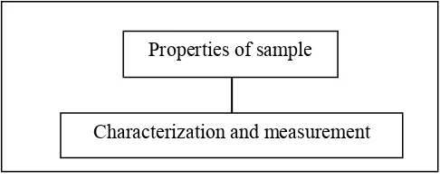
In order to obtain the objectives of this research, the scope of the study has performed as shown in Figure 1.1. The scope of this project is to study the properties of sample after undergo joining using resistance spot welding by using different welding tip. Sheets metal of SPCC and SPHC is used as a sample in this project. The sample will be cut into ASTM standard size 30mm x 100mm with thickness 1mm for testing.
In general, this work study is focused on the characterization and measurement of the sample after the joining process. The evaluation of this research is from fourstandard testing which are tensile strength of the welded joint of sheets metal being evaluated in terms of the maximum load (N) and the displacement of the welded specimens (mm) by using tensile test machine, liquid penetrant testing (NDT) is used to detect the internal flaws by using dye penetrant solvent removable aerosol cans, visual test using calliper to measure the nugget diameter (mm) of the specimen. Last but not least, microscopicexamination to get the microstructure for welding fusion of the specimen. Three specimens are involved in each testing, 24 specimens before weld size 30mm x 100mm will be provided for SPCC and 24specimens’ before weld size 30mm x 100mm will be provided for SPHC.
Figure 1.1: Project Work scope
1.4 Conclusion
CHAPTER 2
LITERATURE RIVIEW
2.0 Introduction
This chapter discussed literatures of the resistance spot welding, their background, principle, parameter and welding tip. Other than that, material SPCC and SPHC are also being discussed.
2.1 Resistance spot welding
Resistance spot welding is one of the oldest electric welding processes in use by industry today, especially in the automotive industry. It is a joining process in which coalescence of the metal sheets is produced at the faying surface by the heat generated at the joint by the resistance of the work to the flow of electric current (Han Z, et al. 1993).
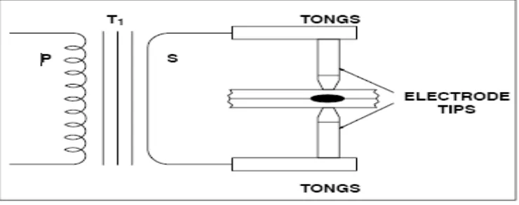
Figure 2.1: Resistance spot welding machine with work
The size and shape of the individually formed welds are limited primarily by the size and contour of the electrode faces. The weld nugget forms at the laying surfaces, as shown in Figure 2.1, but does not extend completely to the outer surfaces. In section, the nugget in a properly formed spot weld is round or oval in shape. Spacing between adjacent spot welds or rows of spot welds must be enough to prevent shunting or to limit it to an acceptable amount (Miller, 2012).
2.2 Principle of the resistance spot welding
Resistance Spot Welding is done when current is caused to flow through electrode tips and the separate pieces of metal to be joined. The operation of spot welding involves a coordinated application of current of the proper magnitude for the correct length of time. This current must pass through a closed circuit. The resistance of the base metal to electrical current flow causes localized heating in the joint, and the weld is made.
2.3 Spot welds parameter
2.3.1 Electrode Force
The electrode force is required to squeeze the metal sheets to be weld and joint together. This requires a large electrode force because the weld quality would not be good enough. However, the force must not be too large as it might cause other problems. When the electrode force is increased the heat energy will decrease. So, the higher electrode force needed a higher weld current. When weld current becomes too high, spatter will occur between electrodes and sheets. This will cause the electrodes to get stuck to the sheet.
2.3.2 Squeeze Time
Squeeze Time is the time interval between the initial application of the electrode force on the work and the first application of current. Squeeze time is necessary to delay the weld current until the electrode force has attained the desired level (Entron, 2014).
2.3.3 Weld or Heat Time
Weld time is the time during which welding current is applied to the metal sheets. The weld time is measured and adjusted in cycles of line voltage as with all timing functions. As the weld time is, more or less, related to what is required for the weld spot, it is difficult to give an exact value of the optimum weld time. For instance:
• Weld time should be as short as possible.
• The weld parameters should be chosen to give as little wearing of the electrodes as possible. (Short welded time.).
• The weld time might have to be adjusted to fit the welding equipment in case it does not fulfil the requirements for the weld current and the electrode force. (A longer weld time might be needed.).
• The weld time shall cause the indentation due to the electrode to be as small as possible. (A short welded time.).
• The weld time shall be adjusted to welding with automatic tip-dressing, where the size of the electrode contact surface can be kept at a constant value. (A shorter welded time.) (Entron, 2014).
2.3.4 Hold Time (cooling-time)
Hold time is the time, after the welding and occurred when the electrodes are still applied to the sheet to chill the weld (time that pressure is maintained after weld is made.). Hold time is necessary to allow the weld nugget to solidify before releasing the welded parts, but it must not be to long as this may cause the heat in the weld spot to spread to the electrode and heat it. The electrode will then get more exposed to wear. Further, if the hold time is too long and the carbon content of the material is high (more than 0.1%), there is a risk the weld will become brittle (Entron, 2014).
2.3.5 Weld Current
The weld current should be kept as low as possible. When determining the current to be used, the current is gradually increased until weld spatter occurs between the metal sheets. This indicates that the correct weld current has been reached. Weld current also influences the value of nugget diameter. Different value of current, it will produce different dimension of the nugget diameter (Entron, 2014).
Figure 2.2: Welding Cycle
2.4 Electrode tip
Copper is the base metal normally used for resistance spot welding tongs and tips. The purpose of the electrode tips is to conduct the welding current to the workpiece, to be the focal point of the pressure applied to the weld joint, and to conduct heat from the work surface. The tips must to maintain their integrity of shape and characteristics of thermal and electrical conductivity under working conditions (Miller, 2012).
Electrode tips are made of copper alloys and other materials. The Resistance Welders Manufacturing Association (RWMA) has classified electrode tips into two groups:
Group A − Copper based alloys Group B − Refractory metal tips
The groups are further classified by number. Group A, Class I, II, III, IV, and V are made of copper alloys. Group B, Class 10, 11, 12, 13, and 14 are the refractory alloys. Group A, Class I electrode tips are the closest in composition to pure copper. As the Class Number goes higher, the hardness and annealing temperature values increase, while the thermal and electrical conductivity decreases (Miller, 2012).
Group B compositions are sintered mixtures of copper and tungsten, etc., designed for wear resistance and compressive strength at high temperatures. Group B, Class 10 alloys have about 40 percent the conductivity of copper with conductivity decreasing as the number value increases. Group B electrode tips are not normally used for applications in which resistance spot welding machines would be employed (Miller, 2012).