accredited by DGHE (DIKTI), Decree No: 51/Dikti/Kep/2010 87
Motor Noise and Vibration Test Research
Zhongjie Wang, Jingnan Zhang, Yongchun Liang
Hebei University of Science and Technology
26 Yuxiang Street,Yuhua District, Shijiazhuang, China
e-mail: [email protected]
Abstrak
Banyak faktor seperti gesekan, getaran dan sebagainya dapat dihasilkan oleh gangguan serta derau tak normal dari motor. Berdasarkan deteksi dan analis dari derau dan getaran, kita dapat mengidentifikasi dan menghilangkan gangguan yang terjadi pada sebuah motor. Hal ini sangat membantu, tidak hanya dalam hal memastikan keberlangsungan produksi tapi untuk mencegah terjadinya kecelakaan. Dalam karya ilmiah ini, kami dengan ringkas dan jelas mengenalkan prinsip pembangkitan derau motor. Sebuah laptop dan program Lab View digunakan untuk merancang sistem percobaan yang bertujuan guna mendeteksi dan menganalisa getaran dan derau motor. Perangkat keras pendeteksi derau tersusun dari mikropon eksternal dan komputer dengan sound card. Perangkat keras pendeteksi getaran tersusun atas sensor getaran dan kartu akuisisi data. Program Lab Fiew dikombinaskikan dengan analisa FFT digunakan untuk membangun akuisisi sinyal, perekaman dan analisis spectral dari derau sinyal. Deteksi dan analisis derau yang berasal dari sebuah motor dc magnet tetap dan sebuah motor tak serempak tiga fasa membuktikan bahwa platform percobaan deteksi getaran dan derau motor memenuhi syarat untuk keperluan riset serta uji motor. Sistem deteksi dan analisis ini memiliki antar muka manusia-mesin yang baik dan mudah dioperasikan.
Kata kunci: motor, derau, lab VIEW, analisis spektrum, FFT
Abstract
Some factors, such as friction, vibration, and so on, can result in the fault and abnormal noise in the motor. Based on the detection and analysis of noise and vibration, we can identify and eliminate the faults of the motor. This is helpful not only to ensure the completion of production tasks, but also to prevent accidents. In this paper, we briefly introduce the motor noise generation principle. A laptop computer and LabVIEW software are used to design the experiment system to detect and analysis the noise and vibration of motor. External microphone and computer with sound card constitute noise detection system hardware. Vibration sensor and the data acquisition card constitute vibration detection system hardware. LabVIEW software combined with FFT analysis is used to realize the noise signal acquisition, recording and spectral analysis. Detecting and analyzing the noise of the permanent magnet DC motor and three-phase asynchronous motor proves that the motor noise and vibration detecting experimental platform is fully meet the requirements of motor test and research. This detection and analysis system has a good man-machine interface and strong operability.
Keywords: Motor, Noise, Vibration, Lab VIEW, spectrum analysis, FFT
1. Introduction
At present, the motor is the main power in the industrial and widely used in social production [1-2]. When the motor works, it brings noise, the motor vibration and noise problem will cause vibration and noise problem of related products, which may affect product quality. Motor noise and vibration research is very complex, involving the electromagnetic, mechanical vibration, acoustics, mathematics and many other disciplines. In general, the noise of analysis is more difficult than vibration analysis, and the motor of the complexity also increased the difficulty of research.
ISSN: 1693-6930
TELKOMNIKA Vol. 11, No. 1, March 2013 : 88 – 94 88
2. Motor Noise Mechanism Analysis
When the motor operates, there are usually multiple noise sources at the same time. They can be divided into three categories [8]:
(i) Electromagnetic noise: When power is applied to the motor, there are electromagnetic force in the air gap between the stator and rotor. This will generate rotational torque wave or pulse wave and cause the vibration of the motor and emit noise. This type of noise is called electromagnetic noise. The amplitude and frequency of electromagnetic noise are influenced by the motor air gap within the harmonic magnetic field in the air gap of the motor, the amplitude of the electromagnetic torque, frequency, and the number of poles and the vibration characteristics of the stator.
(ii) Mechanical noise: mechanical noise is mainly caused by the bearing and brush of the motor. The mechanical noise is related to the materials, manufacturing quality and the assembly process of the motor.
(iii) Air dynamic noise: It is produced by the cooling fan in the motor. The influence factors include the fan type, the import and export structure design of the fan and ventilation. In high speed motor, air dynamic noise is the dominant noise.
Here, noise classification is give out in Table 1 [9].
Table 1. The motor noise and vibration spectrum analysis
3. Motor Noise and Vibration Test System 3.1. Noise Detection Hardware
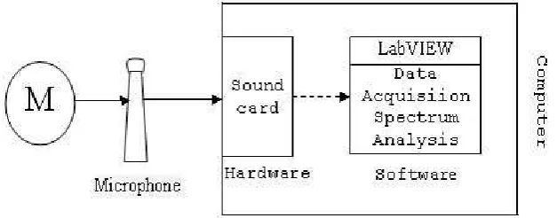
The noise test system is constructed by a microphone and a laptop as shown in figure 1.
Figure 1. The hardware of noise testing system
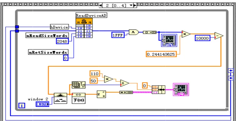
3.2. Noise Detection Software
LabVIEW can help users quickly realizing the real time signal acquisition [10], analysis and display. The LabVIEW noise acquisition and analysis procedure consists of (here, list maim module) as shown in Figure 2.
Main frequency Noise classification Reason F = 2KHz ~ 5KHz has
obvious peak
The noise and vibration of bearing
The poor quality of the bearing itself; Bearing, bearing chamber with improper F = 1KHz~2KHz has
obvious peak
Bearing axial vibration and noise
Motor without axial elastic device or device defect; Motor process of poor quality; Bearing raceway
curvature radius is small F = 500Hz~1KHz has
obvious peak
Resonance noise Electromagnetic vibration harmonic resonance
F = 50Hz~500Hz has obvious peak
ISSN: 1693-6930
TELKOMNIKA Vol. 11, No. 1, March 2013 : 88 – 94 90
4. Experiment
4.1. Noise Experiment of The Permanent Magnet DC Motor
In order to ensure that the measurement error is less than 1dB, the laptop is located at opposite the tested motor center position and the horizontal distance is about 0.5 m [15].
The test motor is an electric vehicle permanent magnet DC drive motor. The basic parameters are listed as follow:
Rated power : 1000 W Rated voltage : 48 V Rated speed : 650 r/ min Rated current : 26 A
Weight : 10kg
Geometric size : 19.5cm x 42.5cm Cooling method : fan cooling.
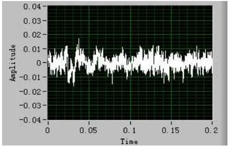
Before we test the working noise of the motor, we must know the environment noise. The noise of the experimental environment is shown in Figure 5. From Figure (b), we can see that the maim frequency component is located at about 90Hz. The peak is about 190dB.
(a) Time-domain waveform of the environment noise
( b ) Frequency spectrum of the environmental noise
Figure 5. The environmental noise
This waveform is the mechanical noise and environmental noise [16-17]. Because we have known the environmental noise, we can obtain the electromagnetic noise and mechanical noise easily.
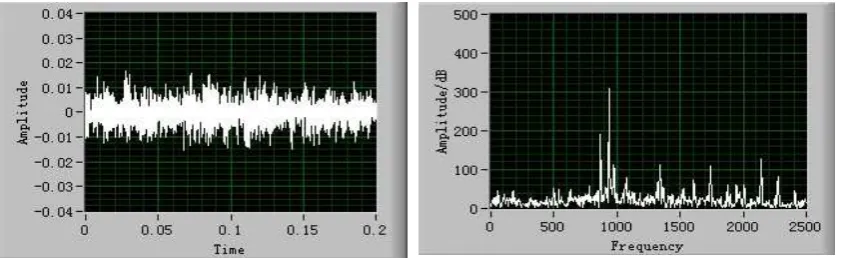
Figure 6 gives out the running noise of the permanent motor. Figure (a) gives out the time domain waveform of the electromagnetic noise. Figure (b) gives out the frequency spectrum of the electromagnetic noise. There are plentiful frequency components distributed in the frequency of 50Hz ~2500Hz in electromagnetic noise. The peak frequency is at about 900 Hz and the peak is about 320 dB.
Figure (c) gives out the time domain waveform of the mechanical noise. Figure (d) gives out the frequency spectrum of the mechanical noise. The peak frequency components are at about 90 Hz and the peak is about 230 dB.
4.2. Noise Experiment of Three-Phase Asynchronous Motor
The experimental motor is a Y90S-4 three-phase asynchronous motor. The basic parameters are listed as follow.
Rated power : 110 kW
Rated voltage : 380 V Rated speed : 1400 r/min Rated current : of 2.8 A Connection mode : star connection
Weight : 22 Kg
( a ) Permanent magnet electromagnetic noise of the motor domain map
( b) Permanent magnet motor electromagnetic noise spectrum analysis diagram
( c ) Permanent magnet motor mechanical noise time-domain graph
( d ) The frequency spectrum of the permanent magnet motor mechanical noise
ISSN: 1693-6930
TELKOMNIKA Vol. 11, No. 1, March 2013 : 88 – 94 92
The humidity of the environmental is 20% and the temperature is 22 0.
Figure 7 gives out the electromagnetic noise and mechanical noise of the three-phase asynchronous motor.
(c) Three-phase asynchronous motor mechanical noise time-domain graph
(d) Three-phase motor mechanical noise spectrum analysis diagram
Figure 7. Three-phase asynchronous motors running noise
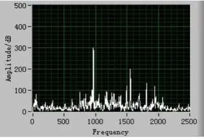
From Figure (b), we can see that there are three parent frequency component at 900 Hz, 1400 Hz and 1700 Hz. The peaks of this frequency are 270 dB, 420 dB and 410 dB separately. There are plentiful frequency components during 1000Hz ~1500 Hz and 1500 Hz ~2200 Hz.
(a) Electromagnetic noise time-domain waveform of the three-phase asynchronous
motor
(b) Three-phase asynchronous motor electromagnetic noise spectrum analysis
and 1 ork of the test
ISSN: 1693-6930
TELKOMNIKA Vol. 11, No. 1, March 2013 : 88 – 94 94
The vibration and noise of permanent magnet DC motor is caused by the unbalanced magnetic force of switching coil, and also caused by the electromagnetic vibration of the coil. The coil of the permanent magnet motor is 3 phase in general, most of the switching time is a square wave or PWM wave [18]. The magnetic field strength of the switching time will produce large fluctuations, which causes the vibration of the motor and the electromagnetic noise.
The factors of the causing noise and vibration of the thee-phase asynchronous motor includes fundamental magnetic flux, high-order harmonic of the electromagnetic noise, electromagnetic imbalance and mechanical imbalance [19].
The noise and vibration test system can be used to evaluate the condition of different motors.
References
[1] Hongyan L. Based on The DSP Motor Noise Signals Research and On-line Detection System. Nanjing: Nanchang University. 2008.
[2] Fabin C, Baoping T, Ling Z. Sound Intensity Method in The Application of Motor Noise Test. Journal of Chongqing University. 2004; 27(11): 11-14.
[3] Zaizhou W, Chunxiang Z, Feng L. Electric Vehicle Based on Microphone Array Motor Fault Diagnosis System Research. Micro Motor. 2010; 12(8): 25-28.
[4] Hu D. Machine Sound Signal On-Line Monitoring System Development Based on Virtual Instrument. Nanjing: Nanjing University of Aeronautics & Astronautics. 2007.
[5] Dongwei T, Jun A, Qizhi L. Machine Tool Noise Test and Analysis System Based on Sound Card and LabVIEW. Laboratory Research and Exploration. 2008; 27(9): 61-64. [6] Xiaoling C, Xueming S, Ying L. Virtual Instrument Erformance Est and Experiment Based
on The LabVIEW Sound Card. Laboratory Research and Exploration. 2010; 29(1) :25-27. [7] Li W, Peng Y. Virtual Oscilloscope Design and Realization Based on LabVIEW. Laboratory
Research and Exploration. 2010; 29(1): 62-64.
[8] Xianjun W, Zhiming L. Motor Vehicle Noise Mechanism and Reduction Method. Micro Motor. 2003; 15(1) :14-16.
[9] Yingjing W. LABVIEW in The Application of Fault Diagnosis Expert System of Motor. Explosion Proof Motor. 2005; 10(3): 19-21.
[10] S Nandi, H Toliyat. Condition Monitoring and Fault Diagnosis of Electrical Machines A Review. In Proceedings IEEE-EMDC Conference. Seattle, WA. 1999; 352-358.
[11] CzeslawT, Kowalski Orlowska-Kowalska. Neural Networks Application for Induction Motor Faults Diagnosis. Mathematics and Computers in Simulation. 2003; (63): 435-448.
[12] LB Jack, AK Nandi. Fault Detection Using Support Vector Machines and Artificial Neural Networks. Mechanical Systems and Signal Processing. 2002; 2-3(16):373-390.
[13] Sanna Poyhonen. Support Vector Machine Based Classification Induction Monitoring of Induction Motors. Helsinki University of Technology; 2004.
[14] HasanOeak, Kenneth A LoParo. Estimation of The Running Speed and Bearing Defect Frequencies of An Induction Motor from Vibration Data Processing. Mechanical System and Signal. 2004; 18: 515-533.
[15] JK Hammond, PR White. The Analysis of Non- Stationary Signals Using Time-Frequency Methods. Journal of Sound and Vibration.1996; 190(3): 308-336.
[16] Guoping H, Kun W. The LabVIEW7. 1 Programming and Virtual Instrument Design. Beijing: Qinghua University Press. 2005.
[17] Bo-Suk Yanga, Seok KWon Jeonga, Yong-Min Ohb, Andy Chit Chiow Tanc. Case-based Reasoning System with Petri Nets for Induction Motor Fault Diagnosis. Expert Systems with Applications. 2004; 27(22): 301-311.
[18] Ron Kohavi, George H John. Wrappers for Feature Subset Selection. AIJ Special Issue on Relevance.1997; 123(4): 1-43.